Transcription
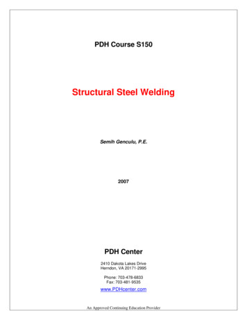
Journal of Engineering and Applied Sciences 15 (1): 261-266, 2020ISSN: 1816-949X Medwell Journals, 2020Comparison of Welding Process SAW and FCAW on ASTM A36Herman Pratikno and Wimala L. DhanisthaDepartment of Ocean Engineering, Institute Teknologi Sepuluh Nopember, Surabaya, IndonesiaAbstract: Underwater welding is the most important in the offshore field. Welding method that is often usedis the method of welding SAW (Submerged Arc Welding). The use of this welding method due to its low cost,relatively faster process, lighter and more varied form of construction. The SAW welding principle is almostthe same on the SMAW (Shielded Metal Arc Welding) welding process but the flux present on the SAW isshaped like sand while in SMAW the electrode is enclosed by flux. In addition to the SAW method normallyused in the shipping industry is FCAW (Flux Cored Arc Welding). The use of this welding method is due toits low cost, relatively faster process, uniform welding result and machine used automatically. This weldingusually uses an additional protective gas to avoid being contaminated with air around the welding area.Key words: SAW, FCAW, ASTM 36, construction, machine, weldingand Izod. But the test is often used charpy method.Mechanical test other than tensile test and notch test thatis hardness test. Where this test aims to determine theresistance of a material to the load identitor. One of theidentities used is the diamond pyramid in which theidentitor is present in the Vicker hardness method.INTRODUCTIONWelding is the most important in shipbuilding.Variations of welding refers to Welding ProcedureSpecification (WPS) in order to obtain good weldingresults. Welding is often used today is electric arcwelding. Welding methods are often used by the shippingindustry such as the method of welding weldingSubmerged Arc Welding (SAW). The use of this weldingmethod due to its low cost, relatively faster process,lighter and more varied form of construction. SAWwelding principle is almost the same on Shielded MetalArc Welding (SMAW) welding process. SMAW ismanual welding while SAW is automatic welding. Inaddition to the SAW method normally used in theshipping industry is Flux Cored Arc Welding (FCAW).The use of this welding method is due to its low cost,relatively faster process, uniform welding result andmachine used automatically. FCAW is one type of electricweld that supplies the electrode filler mechanically intothe arc formed between the electrode filler tip and theparent metal. This welding usually uses an additionalprotective gas to avoid being contaminated with airaround the welding area. Protective gases generally useCO2 gas or a mixture of CO2 and argon.The material before being applied must be known toits mechanical properties by conducting tests such astensile test. This test aims to determine the resistance ofa material to the static force given slowly. This tensile testis one of the most important tests to do because with thistest it can provide various information about metallicproperties. In addition to other test tensile test is the testnotch or impact test. This test is performed to determinethe tenacity of a material by giving a sudden and rapidburden. Methods in this test there are two namely CharpyMATERIALS AND METHODSSubmerged arc welding: Submerged Arc Welding(SAW) is one of the welding process of electric weldingtype where the material is welded by heating and meltingthe parent metal and electrode by the electric arc locatedbetween the parent metal and electrode. The electrode isa continuously supplied filler metal reel and this weldingis granulated as a sandstone granule to protect fromoutside air contamination. SAW welding principle isalmost the same as SMAW but flux is used in the form ofsand grain while SMAW elektoda is covered by flux. Inaddition SAW is an automatic welding while SMAWmanual welding. The SAW welding process does notrequire pressure. The electrode is a continuously suppliedfiller metal reel and this welding is granulated as asandstone granule to protect from outside aircontamination. The SAW welding principle is almost thesame as SMAW but the flux used is sand grain whileSMAW elektoda is covered by flux. In addition SAW isan automatic welding while SMAW manual welding.There are advantages and disadvantages of usingSAW method. The advantages of this method can be usedto weld various types of structural steel and alloy steelincluding low carbon steel, low alloy steel, heat-treatedsteel, high alloy steel such as stainless steel. In addition,because the SAW process is automatic, it is not necessarythat high welding skills and changes in weldingCorresponding Author: Herman Pratikno, Department of Ocean Engineering, Institute Teknologi Sepuluh Nopember, Surabaya,Indonesia261
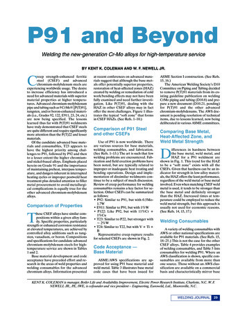
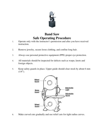
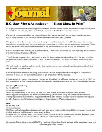
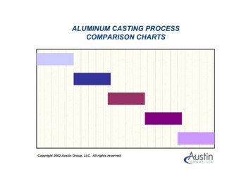
J. Eng. Applied Sci., 15 (1): 261-266, 2020Table 1: SAW welding parameterLayer123Filler metal---------------------------------ClassDia. rode guide andcontact -PolarityAmpereDCSP300DCSP350DCSP350Volt range Travel speed (mm/sec)26-303.8128-323.4828-323.48Travel directionFrom flux hoppeerMolten fluxGranular fluxSlagSolidifiedweld metalMolten welld metalFig. 1: SAW Jeffur (2012)CCCCCCCCMaterial specification: ASTM A-36Dimensions: 400 150 12 mmWelding process: SAWConnection type: butt joint single V-GrooveWelding position: 1 GMetal filler: A5.17-EH12K (OK Autrod 12.32),Ø 3.2 mmFlux: F7A5-EH12K (OK Flux 10.71)Flow welding: DC SP and shielding gasFig. 2: SAW weldingLayer 3: On the third layer is the upper area of the weldor capping. At this stage the elekrode used is a metal fillerwith type EH12K with a diameter of 3.2 mm andmenggukan flux in the form of sand with type F7A5. Thecurrent used in root weld is 350 A and a voltage range of28-32 V. The time taken in the 1 pass weld is 115 sec, sothat, the welding speed is 3.48 mm/sec (Fig. 2).techniques performed by the welder do not have mucheffect on the quality of welding. For the weakness of thismethod is because the process is automatic then its use ismore limited when compared to welding by hand or semiautomatic such as the position of welding is limited onlyin the horizontal position. An invisible bow due to theflux grain that covers, the incorrect welding determinationcan thwart the entire welding result (Table 1 and Fig. 1).Flux cored arc welding: Central-core core flux/middlecore protective weld is commonly known as FCAW (FluxCored Arc Welding) welding process is one of thewelding process using a metal filled filler arc in theform of electrodes that can be fed continuously with thework plane is usually tubular. FCAW welding isoperated semi-automatic or automatic. Applications forsemi-automatic FCAW welding are often used in theworld of steel structure fabrication. Usually performed onhard welding diaskes, short weld production or weldingposition out like vertical or overhead. In general, FCAWwelding uses semi-automatic operation. According to itsusefulness FCAW is classified into two types of variationdepending on the protective electrode ie FCAW-ss andFCAW-g. Welding FCAW-ss (Self Shielded Flux CoreArc Welding) is the process of protecting melt weld metalby using gas from the evaporation or reaction of the fluxcore. While welding FCAW-g protection with dual gas,that is protecting melt weld metal by using own gas alsoadded protective gas that come from outside sistemu.Generally, the gas used is carbon dioxide (CO2) as aprotective gas although, it can also use other gas mixtureslike argon (Fig. 3).Layer 1: In the first layer is also often called root weld orbasic welding on the material. Elekrode used in theform of metal filler with type EH12K with 3.2 mmdiameter and menggukan flux in the form of sand withtype F7A5. The current used in root weld is 300 A and thevoltage range is 26-30 V. The time taken in the 1pass weld is 105 sec, so that, the welding speed is 3.81mm/sec.Layer 2: The second layer is an electrode or fill area. Atthis stage the elekrode used is a metal filler with typeEH12K with a diameter of 3.2 mm and menggukan fluxin the form of sand with type F7A5. The current used inroot weld is 350 A and a voltage range of 28-32 V. Thetime taken in the 1 pass weld is 115 sec, so that, thewelding speed is 3.48 mm/sec.262
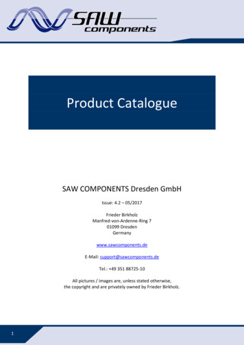
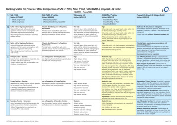
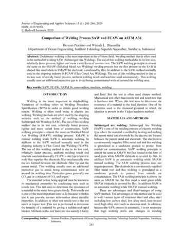
J. Eng. Applied Sci., 15 (1): 261-266, 2020Table 2: FCAW welding parameterFiller rProcessClassDiameter eDCSP120DCSP120DCSP120WWeldmetalmBase metalTravel speed (mm/sec)2.222.452.35Layer 2: The second layer is an electrode or fill area. Atthis stage the elekrode used is a metal filler with typeE71T-1C with a diameter of 1.2 mm and menggukan CO2protective gas. The current used in the root weld is 120 Aand the voltage range is 22-27 V. The time taken inwelding 1 pass of 163 sec, so that, the welding speed of2.45 mm/sec (ASME BPVC-IX-2013, 2013).Gas nozzleMolten slag ShieldinggasSlagVolt range22-2722-2722-27Wire guidee andcontact tuubeFlux filleed tubularwire electrodePoweredd metal fluxand slaag formingmaaterialsA andArcmetaal transferLayer 3: On the third layer is the upper area of the weldor capping. At this stage the elekrode used is a metal fillerwith type E71T-1C with a diameter of 1.2 mm andmenggukan CO2 protective gas. The current used in theroot weld is 120 A and the voltage range is 22-27 V. Thetime taken in welding 1 pass of 170 sec, so that, thewelding speed of 2.35 mm/sec.Molteenweld poolFig. 3: FCAW Jeffur (2012)RESULTS AND DISCUSSIONAnalysis dataRadiographic test: Radiographic tests are conducted todetermine whether or not a defect is a specimen that cannot be seen by the naked eye. Where this specimen isgiven radiation rays to detect any defects or not.According to ASME IX, the result is expressed acceptedif the radiographic result is no defect along the weld.While the results are rejected if the length of porosityexceeds 20% of plate thickness. The most commonly usedradiographic method for welded joints is directradiography, i.e., images photographed radiographicallydirectly onto x-ray film sheets. In a radiographic test, asany damage photographed to visualized radiographs, thetype of damage can be identified relatively easily.However, since, x-ray films should be placed on thespecimen at the rear of the welding area, the film isdifficult to use on certain types of welded joints. Toenhance the sensitivity of the film, strictly use sensitiveflorescent paper or metal foil paper sensitive to thefilm during the radiographic process.SAW welding is very rare because SAW engine hasadvantages such as welding areas that have good qualitydue to fluid covered by flux where the possibility ofporosity is very small. Radiographic test results on FCAWwelds are declared rejected which means there are defectsin the welding results in Fig. 5. The defects contained inFCAW welding results are worm hole or wormhole. Thisis caused by the gas from outside into the weld andtrapped there. In addition porosity is caused by dirtyworkpieces.Fig. 4: FCAW weldingCCCCCCCCCMaterial specification: ASTM A-36Dimensions: 400 150 12 mmWelding process: semi automatic FCAWConnection type: butt joint single V-GrooveWelding position: 1 GMetal filler: A5.20-E71T-1C, Ø 1.2 mmFlow welding: DC SPShielding gas: CO2Backing: ceramicLayer 1: In the first layer is also often called root weld orbasic welding on the material. Elekrode used is a metalfiller with type E71T-1C with a diameter of 1.2 mm andmenggukan CO2 protective gas. The current used in theroot weld is 120 A and the voltage range is 22-27 V. Thetime taken in welding 1 pass of 180 sec, so that, thewelding speed of 2.22 mm/sec (Table 2 and Fig. 4).263
J. Eng. Applied Sci., 15 (1): 261-266, 2020(a)results of welds produced. The ultimate power of SAWwelding is 522.07 MPa while the ultimate welding powerof FCAW is 516.4 MPa in Table 3. It is like the previousresearch by Hadi and Eko Sasmiko that the yield oftensile strength between welding SAW and FCAW showsthe same result because it shows no significant difference,the difference is 1%.The tensile strength of the two welds can be passedin accordance with ASME section IX 2013 standard.Where the weld strength value of both welds exceeds thetensile strength of the parent metal. The value of the yieldstrength of the parent metal weld is 335 MPa and theultimate powers of 452 MPa.(b)Fig. 5(a-b): Radiografi SAW dan FCAWTable 3: Summary Kekuatan TarikTensile strengthCodes(MPa)Baja ASTM A36335.0SAW346.3FCAW346.3Hardness test: Hardness tests are the most important andmost widely used in mechanical tests to determine theproperties of metals as well as certain other materials. Thehardness of the material is usually assessed for itsresistance to permanent (permanent deform) press.generally an identor is pressed on the surface of the metalto be tested with a certain load at a certain time intervaland the measurement is obtained from the size and depthof the identor. The main principle of this test is todetermine the suitability of materials in a particularapplication or a particular treatment on an object. Theease of this hardness test is the most common methodperformed in metal and metallic inspection (Chandler,1999).The method used for this final project is Vickersmethod. One method of hardness testing has the objectiveof knowing the durability of a material by providing aload using a diamond pyramid identifier with an angle of136 between the diamond pyramid surface facing eachother with the test material. The reference used is ASTME 92 (ASTME92-82(1997)e3., 1997). Violence of vickersis expressed in the following formula:Ultimate strength(MPa)452.00522.07516.40Tensile test: The tensile test is the most basic materialtest in which the cut material is tested by being drawn inthe direction of the axial force in order to know how thematerial reacts to the ten
Comparison of Welding Process SAW and FCAW on ASTM A36 Herman Pratikno and Wimala L. Dhanistha Department of Ocean Engineering, Institute Teknologi Sepuluh Nopember, Surabaya, Indonesia Abstract: Underwater welding is the most important in the offshore field. Welding method that is often used is the method of welding SAW (Submerged Arc Welding). The use of this welding method