Transcription
Dresden, Germany22 -23 March 2011Rigid Flex Circuit sA Technological OverviewJoseph FjelstadFounder/CEO
Outline What is a Rigid Flex Circuit?Why Use Rigid Flex Circuits?Rigid Flex IssuesRepresentative Rigid Flex ConstructionsSome Rigid Flex ApplicationsFuture of Rigid Flex?SummaryFurther reading
What is Rigid Flex?
What is a Rigid Flex Circuit?Rigid flex circuits are a hybrid structure of rigidand flexible PCBsRigid and flexible circuits are integrated into aunitary interconnection structure to gain specialadvantages .The structures can vary widely in terms ofmaterials and layout but in general, the mostcommon materials are polyimide for the flexiblecircuit portions and FR4 or polyimide laminatesfor the rigid portions
Some examples
Why Rigid Flex?
Why Rigid Flex?Increased Interconnection Density in the 3rd Dimension The demand for increased electronics in an ever smaller space is driving more designto consider volumetric solutions and 3D interconnection is the a key capability forrigid flexReduced Assembly Costs Rigid flex circuits integration of flexible areas with rigid elements which supportcomponents and connectors can significantly reduce the costElimination of Assembly Errors Errors in assembly are prevented in the design process thus eliminating operatortouch errors.Weight Reduction Significant reduction in assembly weight can be achievedImproved Reliability Elimination of numerous solder interconnections yields improved reliability
Rigid Flex Issues
Rigid Flex IssuesIn spite of the advantages, rigid flex circuits also have somedrawbacks The overall cost is greater (in small volumes) Design and process planning are often engineering time intensive Use of modeling is very important to first pass success PI flex materials more expensive than FR4 laminates ( 3X) Low flow adhesives normally are more costly than epoxy prepreg Coverlayers and flexible cover coats also cost more than standard soldermasks Manufacturing is labor intensive, some equipment is unique and rigid flex isnot readily adapted to automation.Still from a system perspective, rigid flex can save time and money
CAD Modeling Saves Time and ReducesErrors
Design ConcernsRigid Flex Circuits Require Special Knowledge and Attention Material choices will impact cost and performance Electrical and mechanical performance is gated by material The designer must understand these issues and make tradeoff decisions whenrequired Material choices will also effect manufacturing Copper thickness, dimensional stability, processing challenges Dealing with transition areas requires special attention Transitions between rigid and flexible areas are critical and frequently a sitewhere failures occur. Rigid flex circuits often require special features to facilitate installationinto the product or application Book binder constructions are unique Consideration must be given to field service
Avoidance of Buckling by Design
Consider Field Service Access
Rigid FlexConstructionVariations
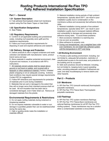
Exemplary Rigid Flex ConstructionsTraditionalRigid FlexStructureCoverlayerextends over allInternal circuitry
Exemplary Rigid Flex ConstructionsShortCoverlayerRigid FlexConstructionCoverlayer doesnot extend overInternal circuits
Exemplary Rigid Flex ConstructionsHybridLaminateRigid FlexConstructionCopper foil coverslapped rigid andflexible materials
Exemplary Rigid Flex ConstructionsSurface FlexRigid FlexConstructionFlex circuit onouter surfaces only
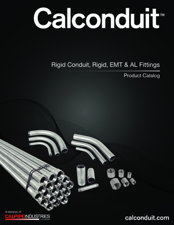
Exemplary Rigid Flex ConstructionsAll RigidMaterialRigid FlexStructureRigid laminatematerial routed tothickness that willbend using suitableradius. Flexiblecoverlay normallyneeded
Reinforced Flex ConstructionFlex CircuitReinforcedwith Stiffener(not rigid flex)Flex circuit bondedto rigid stiffener
Other Solutions Very thin FR4 circuits can provide some flexiblity. Semi-rigid laminates with non woven reinforcementsand low modulus thermoplastic resins (e.g. PTFE,polyester etc.) have been explored in the past andcould be revisited. A caveat when it comes to assembly hightemperature lead-free solders will be cause forcontinuing concern to the industry owing to thehigher Z axis CTE inherent with most rigid flexstructures.
Rigid Flex Marketand Applications
Rigid Flex Circuit ApplicationsRigid flex circuits were developed largely to replace bulkyand heavy wire harnesses but have since migrated tomany new areas of application Clam shell type mobile phonesMobile phone camera modulesMissiles and weapons systemsCamera monitoring systemsElectrical test equipmentLap top computersDigital camerasHearing AidsSatellites
Hand Held Key Board AssemblySource : Interconnect Systems, Inc.
CCD DetectorSource : University of Texas
Liquid Crystal Polymer Rigid FlexSource : Dynaco Corp.
Chip on Board Rigid FlexSource : University of Pennsylvania
Future of Rigid Flex
What is the Future of Rigid Flex? Integration of rigid and flex should see increased useand application in the future Each technology has intrinsic benefits and thesynergy of the combination is highly compelling New structures will offer and should providesignificant opportunities and improvements overcurrent generation solutions. What follows is a description of a prospective way ofmaking rigid flex circuit assemblies with minimalsoldering and/or where the soldered elements aresuitably protected from damage.
Proposed Process for theLow Cost Manufactureof Highly ReliableRigid Flex Assemblies
Background Rigid flex technology offers significant benefit to abroad range of products. One of the problems, however is that the assembliesmust be soldered and high temperature lead freesoldering can damage both the circuit and thecomponents The common failure for most surviving assemblies istypically a solder joint A process which eliminates soldering where possibleshould greatly improve reliability.
Process Background The Occam Process is predicated on the elimination of solderand desirably uses only components with a copper finish,unfortunately nearly all components presently have some sortof finish. While ideally solder will not be applied at some point in thefuture, to obtain immediate benefit of the structures that willbe shown, some accommodation must be made for solderprocessing
Basic Occam Process SequencePatents issued and pending
Traditional Process StepsDesign PCB Assembly1.2.3.4.5.6.7.Create schematicIndentify componentsLayout circuitsValidate signal integrityValidate design DfMValidate design DfRValidate design DfEFabricate PCB .17.18.19.20.21.22.23.24.25.26.27.28.29.Verify RoHS complianceCut core laminas to size & toolClean and coat with resistImage and develop resistEtch and strip resistTreat exposed copperAOI or visual inspect layersCut B-stage to size and toolLay up core and B-stageLaminateX-ray inspect (optional)Drill (stack height varies)Desmear or etchbackSensitize holesPlate electroless copperClean and coat with resistImage an develop resistPattern plate copperPattern plate metal resistStrip plating resistEtch base copperClean and coat with soldermaskImage and developTreat exposed metal (options)Solder, NiAu, Sn, Ag, OSP, etc.Electrical testRoute to shapePackageShipAssemble rocure componentsVerify RoHS complianceVerify component solderabilityVerify component MSL numberKit componentsProcure PCBsVerify RoHS complianceVerify PCB solderabilityVerify PCB High Temp capabilityDesign solder stencil & purchaseDevelop suitable reflow profileTrack component exposure (MSL)(Rebake components as required)Position PCB & stencil solder paste(monitor solder paste)Inspect solder paste results(height and skips)Dispense glue dots (optional)Place componentsInspect for missing partsReflow solderRepeat Steps 13-18 if two sided assy(second set of fixtures required)Perform hand assembly as required(odd sized or temperature sensitive)Clean flux from surface and underVerify low standoff devicesTest cleanlinessUnderfill critical componentsX-ray inspect soldered assemblyIdentify shorts, opens, voids, missingElectrically testRework and repair as neededPackageShip
Modified Process StepsDesign PCB Assembly1.2.3.4.5.6.7.Create schematicIndentify componentsLayout circuitsValidate signal integrityValidate design DfMValidate design DfRValidate design DfEFabricate PCB .17.18.19.20.21.22.23.24.25.26.27.28.29.Verify RoHS complianceCut core laminas to size & toolClean and coat with resistImage and develop resistEtch and strip resistTreat exposed copperAOI or visual inspect layersCut B-stage to size and toolLay up core and B-stageLaminateX-ray inspect (optional)Drill (stack height varies)Desmear or etchbackSensitize holesPlate electroless copperClean and coat with resistImage an develop resistPattern plate copperPattern plate metal resistStrip plating resistEtch base copperClean and coat with soldermaskImage and developTreat exposed metal (options)Solder, NiAu, Sn, Ag, OSP, etc.Electrical testRoute to shapePackageShipAssemble rocure componentsVerify RoHS complianceVerify component solderabilityVerify component MSL numberKit componentsProcure PCBsVerify RoHS complianceVerify PCB solderabilityVerify PCB High Temp capabilityDesign solder stencil & purchaseDevelop suitable reflow profileTrack component exposure (MSL)(Rebake components as required)Position PCB & stencil solder paste(monitor solder paste)Inspect solder paste results(height and skips)Dispense glue dots (optional)Place componentsInspect for missing partsReflow solderRepeat Steps 13-18 if two sided assy(second set of fixtures required)Perform hand assembly as required(odd sized or temperature sensitive)Clean flux from surface and underVerify low standoff devicesTest cleanlinessUnderfill critical componentsX-ray inspect soldered assemblyIdentify shorts, opens, voids, missingElectrically testRework and repair as neededPackageShip
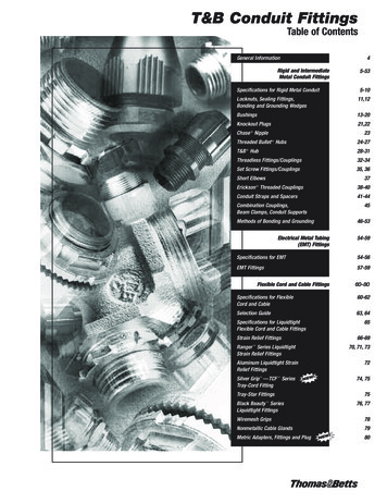
Assemble Functional IslandsUsing Solder on Standard PCB Panel
Encapsulate Assembly on ComponentSide to Provide Uniform Height
Route Assembly into DiscreteFunctional Elements (Packages)and Test to Assure Quality
Place Components into Pre-machinedAluminum Carrier
Aluminum Panel and Parts
Components When Glued in PlaceWill Have a Uniform Height
Components Placed
Apply Flexible Film Layer and CreateHoles to Access Desired Terminations
Polymer Film Covering
Image and Plate Copper CircuitryUsing Microvia Build-up BoardTechnology
Flex Circuit Processing
Apply Coverlayer ExposingTerminations of Interest
Apply Coverlayer
Partially Machine to Thin AreasWhere Etching Will Occur
“Kiss cut” with SRD or Laser Skive
Protect Carrier Areas(might be optional if differential etching isused)
Etch Exposed Aluminum
Image to Protect Aluminum
Remove Resist
Etch and Remove Resist
Apply Strain Relief Fillet
Separate and Bend to Shape
Optional Aluminum Core Rigid Flex Process
Summary Rigid flex (and flexible) circuit technologies willcontinue to expand their sphere of influence intonew areas of electronic interconnection owing toboth their versatility and their intrinsicallybeneficial mechanical and electrical properties thusopportunities should increase Because of the greater levels of engineeringrequired, the cost for more complex structures willbe higher but on a system level, the circuits willoften prove a more cost effective solution. Change is inevitable but adapting to, managing andcontrolling change is a choice.
Further reading : Flexible Circuit Technology 4th Edition, Joseph Fjelstad (www.FlexibleCircuitTEchnology.com) The Printed Circuit Designer's Guide toFlex and Rigid-Flex Fundamentals, Anaya Vardya and DavidLackey mentals/ Printed Circuit Handbook 6th Edition Chapter 69 “Multilayerand Rigid Flex Circuits” Joseph Fjelstad
Mulțumesc foarte mult!
The demand for increased electronics in an ever smaller space is driving more design to consider volumetric solutions and 3D interconnection is the a key capability for . The Printed Circuit Designer's Guide to Flex and Rigid-Flex Fundamentals, Anaya Vardya and David