Transcription
APPLICATION AID #24 Minco 3/2000 920612-5Flex-Circuit Design GuideAll the benefits of a printed circuit board . . .The purpose of this design guide is to enable you todesign a high-quality, manufacturable flexible printedcircuit. While using this guide, keep in mind that thedesign information provided is only a suggestion.Minco takes pride in manufacturing flex-circuits that areconsidered difficult to build. In most cases we can anddo build above and beyond the ‘standard’ circuit,provided that the circuit design and type allow for it. . .in a flexible, versatile package.Minco is certified to MIL-P-50884, Type 1-5. If yourcircuit must meet MIL-P-50884 or IPC-6013, we urgeyou to read IPC-2223 and follow its recommendations.You are encouraged to contact Minco with yourquestions and concerns.ContentsIntroduction. . . . . . . . . . . . . . . . . . . . . . . . . . . . . . . . . . 1-2Electrical . . . . . . . . . . . . . . . . . . . . . . . . . . . . . . . . . . . . 14Specific Applications . . . . . . . . . . . . . . . . . . . . . . . . . . 2-3Terminations . . . . . . . . . . . . . . . . . . . . . . . . . . . . . . . 15-18Circuit Types . . . . . . . . . . . . . . . . . . . . . . . . . . . . . . . . . 4-5Holes . . . . . . . . . . . . . . . . . . . . . . . . . . . . . . . . . . . . . 18-19Design Differences – Flex-Circuit vs. Hardboards . . . . . 6Special Considerations for Rigid-Flex . . . . . . . . . . . . . 20Step-By-Step Approach To Designing a Flex-Circuit . . 6Designing Artworks. . . . . . . . . . . . . . . . . . . . . . . . . . 20-21Minco’s Circuit Codes . . . . . . . . . . . . . . . . . . . . . . . . . . 7Artwork Checklist . . . . . . . . . . . . . . . . . . . . . . . . . . . . . 22Cost Impact of Layer Count . . . . . . . . . . . . . . . . . . . . . . 7Providing Information for a Quote . . . . . . . . . . . . . . 22-23Manufacturing a Flex-Circuit. . . . . . . . . . . . . . . . . . . . . . 8Minco Test Capabilities . . . . . . . . . . . . . . . . . . . . . . . . 23Materials . . . . . . . . . . . . . . . . . . . . . . . . . . . . . . . . . . . . . 9Reference Documents . . . . . . . . . . . . . . . . . . . . . . . . . 23Tolerances . . . . . . . . . . . . . . . . . . . . . . . . . . . . . . . . . . 10Glossary . . . . . . . . . . . . . . . . . . . . . . . . . . . . . . . . . . 24-27How to Improve Flexibility and Bend Radius . . . . . . . . 11Index . . . . . . . . . . . . . . . . . . . . . . . . . . . . . . . . . . . . . . . 28Conductor Width Nomograph . . . . . . . . . . . . . . . . . 12-13Application Aid #24Tel: (763) 571-3121 u Fax: (763) 571-0927 u www.minco.com1
Flex-circuits are a reliable alternative to conventionalwiring. Not only do they improve connection reliability,they simplify assembly and improve componentappearance. Flex-circuits only fit one way for fewerwiring errors during installation and servicing. Thisreduces rework and trouble-shooting time. Byeliminating bulky wires, flex-circuits provide a cleaner,neater appearance.Flex-circuits offer the same advantages of a printedcircuit board: repeatability, reliability, and high density.However, the most important attribute that has madedesigners adopt flex-circuit technology is the capabilityof the flex-circuit to assume three-dimensionalconfigurations. Flex-circuits can flex during installationand maintenance, or in use. With a littleexperimentation and imagination, a flex-circuit can saveup to 75% of the space and/or weight of conventionalwiring.Furthermore, a flex-circuit offers dependability of priceand of product. Recurring costs are lower than manywire harnesses, and since a flex-circuit is more resistantto shock and vibration than a PCB, repair andreplacement costs are less.Below are some of the ways that a flex-circuit can solveyour design/packaging problems. Replace hardboard/ribbon cable assemblies. Replace multiple hardboards and connectors with asingle flex-circuit or rigid-flex circuit. Control impedance with integral ground planes. Control EMI with solid or patterned shield layers. Surface mount components, then fold into tight areas. Feed electrical connections through gaps too narrowfor round wires. Design circuit with exposed conductors for use withconductive elastomer keypads. Integrate heaters, temperature sensors, orwire-wound antenna coils into a flex-circuit (this is anexclusive offering by Minco). Specify pressure-sensitive conductive adhesive toattach circuit to cabinets or enclosures. Use flex-circuits as jumpers between hardboards. Replace tiny wires with easy-to-handle circuits. Buy circuits in panels for automated assembly –circuits can then be routed and clipped out singly. Use low thermally conductive flex materials and foilsfor electronic interface to super-cooled enclosures, orother environments with large internal/externaltemperature differences.2Specific applicationsMilitary/Aerospace Field Accelerometers Aircraft engine fuel controls Aircraft instrument plasma display connection Anti-tank missiles Avionics packages (altitude gauges, engine, fuel, etc.) Computer memory plane High-speed interconnects Dynamically tuned gyroscope Electronic countermeasure instrumentation Forward-looking infrared Laser gyroscope Parachute harness release Passenger address system Radar altimeters Satellites Space shuttle motor controls TorpedoesCommercial Applications Computer printheads Copy machine controls Disk drive head connection Exercise monitoring equipment Fiber optic switching modules High-speed computer printheads Injection molding equipment controls Laser communications Pick-up coils for drill pipe inspection Portable radiosMedical Field Battery connections Blood analyzers Defibrillators (implantable and external) Hearing aids (in-the-ear and implantable) Implantable drug pumps Inductive bone growth stimulators Medical diagnostic equipment Nerve stimulators Nuclear magnetic resonance machines Pacemakers Pacemaker programming controls Shielding Ultrasonic probesTel: (763) 571-3121 u Fax: (763) 571-0927 u www.minco.comApplication Aid #24
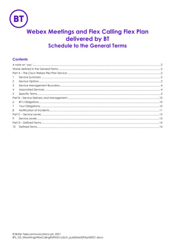
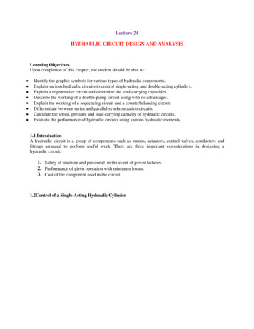
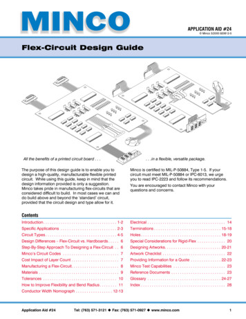
Aerospace field –The flex-circuit below replaces round wiring in an avionicspackage (left). The pins at the front of the flex-circuitconnect to the mother board.Commercial application –A flex-circuit with surface mount components folds to fitinto a laser dimensioning device.Medical field –A double-layer flex-circuit and dual Flex-Coil provide interconnection and communication capabilities in an implantablecardiac pacemaker.Application Aid #24Tel: (763) 571-3121 u Fax: (763) 571-0927 u www.minco.com3
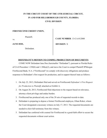
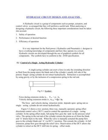
Circuit typesMinco manufactures all types of circuits, from simple to complex. The basic types are:Access HoleSingle-layerPolyimide Cover Mil-P-50884 – Type 1 One conductive layer, either bonded betweenAdhesivetwo insulating layers or uncovered onone side. Access holes to conductors may be oneither one or both sides. Access holeson both sides of a single-layer are more expensivesince the substrate must be drilled or punchedseparately.Polyimide SubstrateCopper Pad Stiffeners, pins, connectors, components are optional.Access HoleDouble-layer Mil-P-50884 – Type 2 Two conductive layers with an insulating layerPolyimide CoverAdhesivebetween, plus cover layers on outer layers. Plated through-holes provide connection. Access holes or exposed pads withoutCopper Padcovers may be on either or both sides;vias can also be covered on both sides.Polyimide Cover Stiffeners, pins, connectors, componentsare leMultilayer Mil-P-50884 – Type 3 Three or more flexible conductive layers with flexibleinsulating layers between each one; outer layers mayhave covers or exposed pads. Plated through-holes for connection. Access holes or exposed pads withoutcovers may be on either or both sides.Access HolePolyimide CoverCopper PadPolyimide SubstratePolyimide LayerPolyimide Substrate Blind or buried vias are possible. Stiffeners, pins, connectors, componentsare optional.AdhesivePolyimide CoverCopper-PlatedThrough-Hole*Adhesiveless base material also available4Tel: (763) 571-3121 u Fax: (763) 571-0927 u www.minco.comApplication Aid #24
Rigid-Flex Mil-P-50884 – Type 4 Two or more conductive layers with either flexible orPolyimide CoverAdhesiverigid insulating material as insulators betweeneach one; outer layers may have coversor exposed pads.Polyimide Cover Rigid-flex is differentiated frommultilayer circuits withstiffeners by havingconductors on the rigidlayers. Platedthrough-holes extendthrough both rigid andflexible layers (with theexception of blind andburied vias).Rigid MaterialRigid-flex alsocosts more. Access holes or exposed pads without covers may beon either or both sides; vias or interconnects can befully covered for maximum insulation.Polyimide SubstratePolyimide SubstrateCopper PadCopper-Plated Through-Hole Minco is capable of sequentially laminated, drilled,and plated circuits, which allows for more flexibility indesigning the circuit. Stiffeners, pins, connectors, components, heat sinks,and mounting brackets are optional. We also manufacture ‘flush’ rigid-flex, where the topsurface of contact areas is level with adjacentadhesive/insulation.Note: The Special Considerations for Rigid-Flex sectionon page 20 provides additional information fordesigning a rigid-flex circuit.Access HolePolyimide CoverAdhesivePolyimide CoverCopper Pad (Layer #2)Copper Pad (Layer #1)PolyimideSubstrateMultilayer, no platedthrough-holes MIL-P-50884 – Type 5 Two or more conductive layers with insulating layersbetween each one; outer layers may have covers orexposed pads. Through-holes are not plated. Access holes or exposed pads without covers may beon either or both sides. Stiffeners, pins, and connectors are optional.*Adhesiveless base material also availableApplication Aid #24Tel: (763) 571-3121 u Fax: (763) 571-0927 u www.minco.com5
Design differences – flex-circuit vs. hardboardsStep-by-step approach to designing a flex-circuitDesigning a flex-circuit is only one step away fromdesigning a hardboard. The most important designdifference to keep in mind is the three-dimensionality ofa flex-circuit. Creative bending and flexing can savespace and layers. Other important differences:1. Read the available literature that is applicable for thecircuit you desire. If the circuit is intended for amilitary/aerospace application, review IPC-6013 andIPC-2223 or MIL-P-50884. Copies are available fromMinco.Applicable sections in this design guide: Manufacturing of a Flex-Circuit Reference Documents Flex-circuits both require and permit looser tolerancesthan hardboards. Because arms can flex, design them slightly longerthan required.Design Tips to Minimize Circuit Cost Always consider how circuits will be ‘nested’ on apanel.vs.BendBendDesiredCircuitEfficient nesting Yield of 14vs.Inefficient nesting Yield of 8 Keep circuits small; consider using a set of smallercircuits instead of one large circuit. Follow recommended tolerances whenever possible. Design unbonded areas only where they arenecessary. If circuits have only a few layers, stiffeners can be farless expensive than designing a rigid-flex circuit. Specify 0.001" of adhesive on the cover material per 1oz. of copper (including plated copper). Building circuits with exposed pads and no coverlayers is sometimes less expensive.62. Define the circuit parameters according to thepackage that uses the circuit. It may be helpful tocut out a paper template to represent the actualcircuit. Experiment with bending and forming thetemplate in order to achieve maximum efficiency.Design a circuit for maximum ‘nesting’ in order to fitas many circuits as possible on a panel.Applicable sections in this design guide: Design Differences: Flex-Circuit vs. Hardboard How to Improve Flexibility and Bend Radius3. Determine the wiring locations and the conductorpaths. This step will determine the number ofconductor layers.Applicable sections in this design guide: Circuit Types Minco Circuit Codes Cost Impact of Layer Count Special Considerations for Rigid-Flex4. Calculate the conductor width and spacing accordingto the current capacity and voltage.Applicable sections in this design guide: Tolerances Nomograph Electrical5. Decide what materials to use.Applicable sections in this design guide: Materials6. Choose the methods of termination and through-holesize(s). Evaluate the bend areas and methods oftermination to determine if stiffeners are needed.Applicable sections in this design guide: Terminations Holes7. Determine what testing you require. Avoidover-specification in order to avoid additional cost.Applicable sections in this design guide: Minco Test CapabilitiesTel: (763) 571-3121 u Fax: (763) 571-0927 u www.minco.comApplication Aid #24
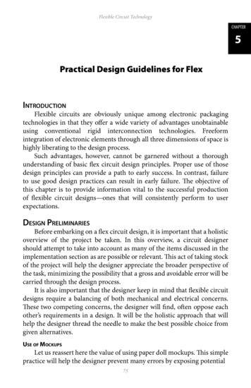
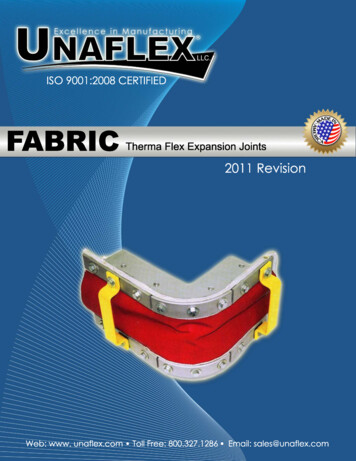
Minco circuit codesCircuit CodeMIL-P-50884 TypeDescriptionE0C-Stiffeners, insulators, wires only. No circuitry.E1A1Single layer - access on one side.E1B1Single layer - major access holes on two sides.E1C1Single layer - access on one side, with stiffeners, pins, orconnectors.E1D1Single layer - access on both sides, with stiffeners, pins,or connectors.E2A5Two layers - no plated through-holes.E2B2Two layers - with plated through-holes.E2C2Two layers - with plated through-holes and stiffeners,pins, or connectors.E2D5Two layers - no plated through-holes, with stiffeners,pins, or connectors.EMxA*5Multilayer flex-circuit -no plated through-holes.EMxB3Multilayer flex-circuit -with plated through holes.EMxC3Multilayer flex-circuit -with plated through-holes andstiffeners, pins, or connectors.EMxD5Multilayer flex-circuit - no plated through-holes, withstiffeners, pins, or connectors.ERxA5Rigid-flex - no plated through-holes.ERxB4Rigid-flex - with plated through-holes.ERxC4Rigid-flex - with plated through-holes and stiffeners, pins,and connectors.ERxD5Rigid-flex - no plated through-holes, with stiffeners, pins,or connectors.* Layer count indicated by x. Example: EM3B1887, ER6C2896Note: Coils are represented with a ‘C’ instead of an ‘E’.Cost impact of layer count6It is in your best interest to experiment withoptions in order to save money. Forexample, consider using two circuits to dothe job of one. Two double-layer circuitscould potentially be less expensive than onefour-layer multilayer circuit. Circuits can alsobe folded in order to save space and layers.5COST MULTIPLIERThe information for the chart to the right wastaken from a sampling of circuits built withMinco’s standard materials. This chart is notintended to be used as a price guide.However, it does show that circuit costgenerally rises with layer count.43210E1AE1BE2BEM3BEM4BER4CCIRCUIT TYPE (CHART ABOVE)Application Aid #24Tel: (763) 571-3121 u Fax: (763) 571-0927 u www.minco.com7
Manufacturing a flex-circuitBuilding a flex-circuit generally involves theBasesame steps from circuit to circuit. However,Materialcertain circuit designs can add cost. Forexample, a single-layer circuit with accessholes on both sides is more expensive thanTopCovera single-layer with access holes on one sidebecause the double-sided access holecircuit must have its substrate drilledBottomseparately. The adjacent flow chart and theCoverillustrations below identify some cost driverissues, such as access holes, platedthrough-holes, etc. The flow chart shows the Adhesivemanufacturing process for a standarddouble-layer circuit with a rAdhesive1. Double-sided material is drilled2. Through-holes are copper-platedConductorPadAccess Hole3. Copper is etched to create conductors and pads84. Polyimide covers are laminated over etched copperTel: (763) 571-3121 u Fax: (763) 571-0927 u www.minco.comApplication Aid #24
MaterialsThis table lists the standard materials and materialthicknesses that Minco has available. Minco’s standardmaterials are in boldface. If the material or thicknessyou require is not listed, consult Minco.Material Function Material TypeSizes/Thicknesses Available Flexible InsulatorKapton* and other polyimidesRigid Substrate(Rigid-Flex)FR-4Variety of thicknesses between 0.003" and 0.125"Polyimide GlassVariety of thicknesses between 0.003" and 0.125"ConductorCopper¼ oz., 1 3 oz., ½ oz., 1 oz., 2 oz., 3 oz., 5 oz., 7 oz., 10 oz.Different hardnesses of copperHalf-hard, rolled-annealed, electrodepositedBeryllium copper0.003": half-hard and quarter-hard0.004": half-hardCupro-nickel (70/30 alloy)0.000625", 0.0009", 0.0013", 0.0019", 0.0023"NickelSilver EpoxyAdhesiveStiffener0.0005", 0.001", 0.002", 0.003", 0.005"0.002", 0.003", 0.005" Modified acrylic0.0005", 0.001", 0.002", 0.003", 0.004"Modified epoxy0.0005", 0.001", 0.002", 0.003", 0.004"Phenolic Butyral0.001", 0.002"Pressure-sensitive adhesive (PSA)0.001", 0.002", 0.005"Preimpregnated material: FR-4,polyimide0.002" -0.008"Copper, Aluminum, & other metals Variety of thicknesses available.Polyimide GlassSee “Rigid Substrate - Polyimide Glass” above.FR-4Variety of thicknesses between 0.005" and 0.125"PolyimideSee “Flexible Insulator -Kapton” above.* Dielectric is 2,000 volts/0.001". Other polyimides are available for special applications.Material is applied as an alternative to standard copper layers.Kapton is a registered trademark of DuPont forpolyimide. Kapton/modified acrylic has a temperaturerating of -65 to 150 C, although circuits will discolor aftera long term exposure at 150 C. For specialapplications, Minco can use an adhesive that willwithstand temperatures of 150 C continuous, and200 C short-term.Application Aid #24Tel: (763) 571-3121 u Fax: (763) 571-0927 u www.minco.com9
TolerancesYou are not limited to the tolerances listed in thissection. Tighter tolerances than those listed can beattained, but often at a higher cost. Accordingly, morerelaxed tolerances will cost less. Even with relaxedtolerances, a flex-circuit will still have a uniformity that isimpossible to achieve with conventional wiring.Flex-circuits have more ‘give’ than the typicalhardboard, so it is not always necessary to specify tighttolerances.CircuitOutline DimensionsDimension in (Profile Tolerance)Inches TrimSRDPunchandDieClustertoCluster§1 0.020 0.015 0.003 0.015 0.015 0.007 0.0035 0.025 0.020 0.007 0.020 0.020 0.012 0.00710 0.030 0.025 0.012 0.025 0.025 0.017 0.01215 0.035 0.030 0.017 0.030 0.030 0.022 0.01720 0.040 0.035 0.022 0.035 0.035 0.027 0.022 Round circuit to next highest increment.§Represents from a group of holes to a group of holes. Holes within a group will have a tolerance of 0.003.Note: Dimensional tolerances are given in inches. See Glossary for description of profile tolerance.TrimmingEach trimming method has advantages anddisadvantages. Generally, hand-trimming is onlyperformed for ‘best effort’ or prototype circuits. Lasertrimming provides hard tooling tolerances for smallquantities of circuits. It is also useful for complex cutoutsnot achievable with other methods.Steel rule dies are best for intermediate quantities andtolerances. Punch-and-dies are recommended for tighttolerances, complex circuits, and/or a high quantity ofcircuits. For more specific information on steel rule diesand punch-and-dies, see the Glossary at the end of thisguide. Other tooling options are available to providenear punch and die tolerances for medium volumequantities.Solder ThicknessMIL-P-50884 does not require a maximum solderthickness, but Minco imposes a 0.0003" minimum onpads, measured at the crest. A 0.0001" minimum isrequired on through-hole walls, also measured at thecrest. Optional plated solder has a 0.0005" tolerancebefore reflow.10Conductor Width and SpacingSee the nomograph on pages 12-13 for calculatingproper conductor width and spacing. Minco can hold a0.004" minimum conductor width/spacing (0.002"minimum at higher cost) on 1 oz. copper
A flex-circuit with surface mount components folds to fit into a laser dimensioning device. Medical field – A double-layer flex-circuit and dual Flex-Coil provide interconnection and communication capabilities in an implantable cardiac pacemaker. Aerospace field – The flex-circuit below replaces round wiring in an avionics package (left).File Size: 460KB