Transcription
Flex Circuits Design GuideDesign Guidelines for Highly Reliable Flexible Printed Circuits Optimized for Manufacturability
The purpose of this design guide is to enable you to design a highly reliable, flexible printed circuitoptimized for manufacturability.While using this guide, keep in mind that the design information provided is only a suggestion. Mincotakes pride in manufacturing flex circuits that are considered difficult to build. In most cases, we dobuild above and beyond the “standard” circuit specifications, provided that the circuit design and typeallow for it.Table of ContentsTable of Contents. 2How to improve flexibility and bend radius. 16Types of Flex circuits . 3Holes . 17The Minco Difference . 4Conductor width, thickness, and spacing. 20How to Get Started . 4Materials . 21Understand How Flex Circuits Work . 4Value Added Design Options . 22Build a Flex Circuit Mock-up . 4Terminations . 22Consider a Mechanical Sample . 4Stiffeners . 23Benefits of Flex Circuits . 5Forming . 24High reliability . 5Population . 24Superior packaging options . 5Custom and Integrated Components . 25Design Options . 7Request a Quote . 26Design Guidelines . 8Providing information for a quote . 26Specification documents:. 8Specify testing requirements . 26Manufacturing a flex circuit . 9Artwork checklist . 26Cost impact of layer count . 9Designing CAD artworks. 27Circuit types. 10CAD/CAM data guidelines . 28Minco’s General Capabilities. 12E2E — Engineer to Engineer . 28Standard specifications . 12Early engineering involvement. 28Testing. 13Ordering and Delivery . 28Marking. 13Place your order with Minco . 28Control impedance and electrical noise . 14Delivery information . 28Conductor width nomograph . 14Glossary . 29Conductor aspect ratio . 14Next Steps . 32Assumptions . 14Conductor width nomograph . 15Standard Design Recommendations . 16Design differences and special considerations. 16page 2 2015 Minco Doc # FCSG014 minco.com
Types of Flex Circuits Flex: Flexible version of a Printed Circuit Board(PCB), with unique capabilities. Flex circuits offer thesame advantages of a printed circuit board:repeatability, reliability, and high density but with theadded “twist” of flexibility and vibration resistance.The most important attribute compelling designers toadopt flex circuit technology is the capability of theflex circuit to assume three-dimensionalconfigurations. Rigid-flex: A blend of rigid and flex emphasizing thebest of both constructions, adding synergisticcapabilities neither possess alone. In its most typicalconfiguration, the rigid-flex is a series of rigid PCBsjoined by integrated flex circuits (with emphasis onthe high percentage of rigid area content). Circuitsdesigned primarily as flex circuits have greatopportunities to increase your design capabilitieswhen integrated rigid areas are added.Rigid areas provide excellent hard mount points forcomponents, connectors and chassis while flexareas offer dynamic flexing, flex to fit, andcomponent mounting poised to take advantage ofthese low mass and vibration resistant zones. Thisblending leads to creative solutions for your mostdemanding applications. High Density Interconnect (HDI): High DensityInterconnect (HDI) flexible circuits offer increaseddesign, layout and construction options over typicalflexible circuits. Each High Density Interconnectincorporates microvias and fine features to achievehighly dense flex circuitry, smaller form factor andincreased functionality. This technology offers betterelectrical performance, access to advancedintegrated circuit (IC) package use, and improvedreliability through the use of microvias and thinnermaterials. Flex-Coils : Custom wire-wound or etched coilsmay be integrated with any of our flex circuit or rigidflex board types. Whether bonded to the surface orencapsulated in a high dielectric and abrasionresistant covering, these assemblies offer specialcapabilities to your coil designs.page 3 2015 Minco Doc # FCSG014 minco.com
The Minco DifferenceMinco provides comprehensive design and engineeringservices, partnering with you at every step of yourproduct life cycle. The Minco difference includes: Minco engineers serve as an extension of yourengineering organization Building partnerships to assure early involvement inthe product cycle and a clear understanding of yourprogram needs Disciplined New Product Introduction (NPI)approach supports fewer product iterations. Solutions oriented engineering staff with extensiveexperience in successfully designing products.How to Get StartedUnderstand How Flex Circuits WorkCarefully review the information in this guide and otheronline resources at www.minco.com. Knowledge of flexcircuit types, capabilities and applications will providethe guidelines you need to design the best flex circuitfor your product needs.Build a Flex Circuit Mock-upThe dynamic nature of flex circuits allows for amultitude of design options. The best method fordetermining the validity of your design is to create aphysical flex circuit mock up. To make your mock-up,follow these steps: Determine the system points to be electrically connected via flex circuitry and terminationmethod(s), such as mating connectors, pins, ZIF,etc.Determine approximate circuit “footprint” that willprovide conductor routing to each terminationlocation.Review schematic or net list details along withspecial electrical requirements, such as planelayers, to determine approximate layer count.Examine sample circuits of similar layer counts todetermine if the proposed design will providesufficient flexibilityReview mechanical requirements to ensure thatbend radii fall within acceptable values for circuitthickness and layer count (refer to IPC-2223 forbend radius guidelines).If possible, construct a virtual mock-up of your flexcircuit in its formed, installed state in a 3D CADpackage (such as SolidWorks). This method allowspage 4 2015 Minco Doc # FCSG014 minco.comyou to design the proper fitment for your specificapplication quickly and precisely, while allowing youto visualize all interference issues in your virtualapplication. Create a flattened 2D CAD part of the flex circuit.Note: If you do not have a 3D CAD system, construct a “paperdoll” outline of your flex circuit using heavy paper and checkfor fit. Make modifications as necessary. Continueconstructing paper dolls and making modifications until thedesired fit is achieved.Use .010" (0.25mm) polyester film to reconstruct the paperdoll to make a representative mock-up. Install and make anydimensional adjustments as necessary.Your circuit outline is now complete and should bereconstructed in your CAD design software package.Using your circuit design software program, positionconnector footprints in the proper locations and routeconductors per schematic or net list. Design rules forrouting conductors on flexible circuits can be found inthe IPC-2223 Sectional Design Standard for FlexiblePrinted Boards. You can also refer to the StandardDesign Recommendations section in this guide.Consider a Mechanical SampleMinco will review your design for possibleimprovements. If there are questions about the properfit of a new circuit, it is advisable to obtain a mechanicalsample. This will allow you to ensure that your flexcircuit has the right form and fit for your product. Formrefers to the physical size, shape and mass of the part,while fit refers to its environmental interfaces, e.g. is itflexible enough to bend for installation, or will it meettemperature requirements? A mechanical sample canhelp you avoid installation problems or latentmechanical issues that could cause failures.To receive a flex circuit mechanical sample proposal: Construct a simple 2-dimensional CAD modelconsisting of the circuit outline, and hole locationsand sizes. Convert the CAD model to a 2-D DXF format andinclude a text file that provides the layer count, anyspecial requirements, and a brief explanation of yourapplication. Also include your name, companyname, postal and email address, and phonenumber. Email this information to sales@minco.com. Minco will provide a response with a lead time formechanical samples and advise if any charges arerequired.
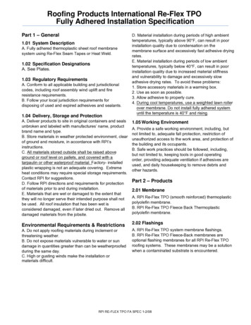
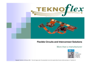
Benefits of Flex CircuitsHigh reliabilityRepeatable installationCompared to discrete wiring, or ribbon cable, a flexcircuit offers a customized repeatable routing pathwithin your assembly. This gives you dependabilitywhere you need it. The longevity of a flex circuit canreduce service calls.Harsh environmentsStandard practice for flex boards is to cover theconductors with polyimide. This dielectric layer protectsyour circuits far beyond the capability of simplesoldermask. Other base and cover materials areavailable for a broad range of ambient conditions.Long duty cyclesBy design, a flex circuit can be made very thin, yetrobust enough to withstand thousands to millions offlexing cycles while carrying signal and power without abreak.High vibrationUnder vibration and/or high acceleration, a flex circuit’sductility and low mass will reduce the impact upon itselfand solder joints. By contrast, a PCB’s highervibrational mass will increase stresses upon itself,components and solder joints.Before: A tangle of wiresconnects four circuit boards.The flex circuit solution: Asingle circuit with 7 stiffenersand 2 connectors provides allthe needed interconnects.After: The package is neat, lightweight, and less susceptibleto connection failure.page 5 2015 Minco Doc # FCSG014 minco.comSuperior packaging optionsFlex circuits can be shaped to fit where no other designcan. They are a hybrid of ordinary printed circuit boardsand round wire, exhibiting benefits of each. In essence,flex circuits give you unlimited freedom of packaginggeometry while retaining the precision density andrepeatability of printed circuits.Flex vs. wiring harness Space and weight reduction: A single flex circuitcan replace several hardboards, cables, andconnectors. Fast assembly: Flex circuits eliminate the need tocolor code and wrap bundles of wire, reducing thechance of assembly rejects and in-service failures.Total installed costs are lower, especially withvolume production. Repeatable wire routing: Eliminate wire routingerrors; reducing test time, rework, and rejects. Robust connections: Flat foil conductors dissipateheat better, carrying more current than round wiresof the same cross-sectional area. Conductorpatterns in a flex circuit maintain uniform electricalcharacteristics. Noise, crosstalk, and impedance canbe predicted and controlled.Flex vs. hard board (PCB) Versatile shape: The most important attributecompelling designers to adopt flex circuit technologyis the capability of the flex circuit to assume threedimensional configurations. Lower mass: With a little experimentation andimagination, a flex circuit can save up to 75% of thespace and/or weight of conventional wiring. Vibration resistance: Recurring costs are lowerthan many wire harnesses, and since a flex circuit ismore resistant to shock and vibrations than a PCB,repair and replacement costs are less. Component mounting: Surface mount componentmounting on flex is achievable using selectivelybonded stiffeners where required.
Rigid-flex Double side component mounting: Rigid-flexcircuits are the ideal solution for flex circuits wheresurface mount components must be mounted onboth sides of the board. Total cost of ownership: The maximum benefit ofrigid-flex is realized when the complete installation isreviewed for total cost of ownership. Using rigid-flexeliminates connections in the flex-to-rigid transitionswhich can improve reliability and improveimpedance control. Most capable/Maximum vibration resistance:Lets you integrate the best capabilities of resistantrigid areas and resilient flex areas. High mass component mounting: When mountinga high mass component, a rigid board is the rightsolution. A rigid-flex board gives you a smoothtransition between rigid and flex areas whilepreserving the benefits of each.Flex-Coils Custom coil winding: State of the art equipmentgenerates a highly repeatable component. Integrated assembly: Allows best packaging ofyour fragile coil in a flex circuit sub-assembly.page 6 2015 Minco Doc # FCSG014 minco.com
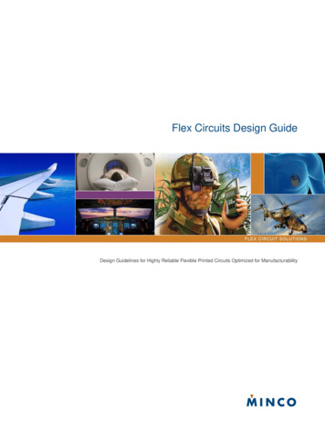
Design OptionsRigid-flexPinsFine linesHybrid hardboard/flex circuits canhave up to sixteen layers. They replacebulky wire harnesses with a compact,robust design.Minco can braze or solder pins tocircuits, either through-holes or asextensions to conductors.0.002" conductors and spaces arepossible.StiffenersConnectorsShieldingAn inexpensive alternative to rigid-flex.Built-in connectors speed your assembly.Optional epoxy potting creates a sealbetween the circuit and connector.Solid or patterned shield planes reducenoise and control impedance of signallines. Use matched impedance flexcircuits for high-speed signal integrity.Assembly palletFactory formingCoilsStiffener material frames the circuit tohold it flat during assembly operations.After soldering or component placement,just clip out and install.Factory formed circuitsfollow tight curves to save space.Minco’s unique flat wound inductive coilscan be laminated into flex circuits.Applications include pacemaker antennasand eddy current generators.Surface mountSelective bondingIntegrated solutionsCombine the space and weight savingsof surface mounting with those of flexcircuits for the ultimate in high-densitypackaging.For better flexibility along circuit arms,individual layers are unbonded andallowed to flex freely. Each layer has itsown substrate and cover.Minco integrates temperature sensors andetched-foil heaters with flex circuits forunified temperature control.page 7 2015 Minco Doc # FCSG014 minco.com
Design GuidelinesSpecification documents:Consult standard specifications and design documentspertaining to your application and circuit requirements.IPC specificationswww.ipc.org IPC-2221A, Generic Standard on Printed BoardDesign IPC-2223, Sectional Design Standard for FlexiblePrinted Boards IPC-4101, Specification for Base Materials for Rigidand Multilayer Printed Boards IPC-4202, Flexible Base Dielectrics for Use inFlexible Printed Circuitry IPC-4203, Adhesive Coated Dielectric Films for Use as Cover Sheets for Flexible Printed Circuitry andFlexible Adhesive Bonding FilmsIPC-4204 Flexible Metal-Clad Dielectrics for Use inFabrication of Flexible Printed CircuitryIPC-6013, Qualification and PerformanceSpecification for Flexible Printed WiringIPC-MF-4562, Copper Foil for Printed WiringApplicationsIPC Position Paper: Transitioning from MIL-P50884C and MIL-PRF-31032 to IPC-6013 andAmendment 1Militarywww.dscc.dla.mil MIL-P-50884 (inactive for new designs), PrintedWiring, Flexible and Rigid-flex for Electronic PrintedWiring MIL-PRF-31032/3A, Printed Wiring Board, Flexible,Single and Double Layer, With or Without PlatedHoles, With or Without Stiffeners, for Soldered PartMounting MIL-PRF-31032/4A, Printed Wiring Board, RigidFlex or Flexible, Multilayer, with Plated Holes, withor Without Stiffeners, for Soldered Part MountingIPC recommends that companies using MIL-PRF31032 specifications for printed circuits alternativelyspecify that flexible circuits be supplied under IPC-6013Class 3 performance requirements. Governmentagencies have generally accepted that this is a COTS(Commercial, Off-The-Shelf) equivalent to MIL-PRF31032. If your circuit must meet performancerequirements of MIL-P-50884, MIL-PRF-31032 or IPC6013; we urge you to read the IPC-2223 designspecification for flexible circuits and follow itsrecommendations.Minco documentswww.minco.com/ Flex-Coils - Technical Specification FC01 Minco/Omnetics Flex Circuit Interconnect SolutionsTechnical Specification FC04 Designing for Flexibility and Reliability - ApplicationAid FAA31page 8 2015 Minco Doc # FCSG014 minco.com
Manufacturing a flex circuitBuilding a flex circuit generally involves the same steps from circuit to circuit. However, certain circuit designs canadd cost. The flow chart and illustrations identify some cost driven issues, such as access holes, plated throughholes, etc. The flow chart shows the manufacturing processfor a standard double-layer circuit with a stiffener.1. Double-sided material is drilled2. Through-holes are copper-plated3. Copper is etched to create conductorsand pads4. Polyimide covers are laminated overetched copperCost impact of layer countThe information for the chart was taken from a sampleof circuits built with Minco’s standard materials. Thischart is not intended to be used as a price guide.However, it does show that circuit cost generally riseswith layer count.It is in your best interest to consider all options tominimize cost. For example, use two circuits to do thejob of one. Two double-layer circuits may be lessexpensive than one four-layer circuit. But the costsavings of the circuit may be offset by additionalassembly requirements. Circuits can also be folded inorder to save space and layers. Each situation isunique. A relatively small amount of time invested inproject assessment can result in significant savingsoverall.page 9 2015 Minco Doc # FCSG014 minco.com
Circuit typesSingle-layer IPC-6013, MIL-P-50884 - Type 1 One conductive layer with an insulating layergenerally on each side.Double-layer IPC-6013, MIL-P-50884 - Type 2 Two conductive layers with an insulating layerbetween them; outer layers may have covers orexposed pads. Plated through-holes provide connection betweenlayers. Access holes or exposed pads without covers maybe on either or both sides; vias can be covered onboth sides. Stiffeners, pins, connectors, components areoptional.Multilayer IPC-6013, MIL-P-50884 - Type 3 Three or more flexible conductive layers with flexible insulating layers between each one; outer layersmay have covers or exposed pads.Plated through-holes provide connection betweenlayers.Access holes or exposed pads without covers maybe on either or both sides.Vias can be blind or buried.Stiffeners, pins, connectors, components areoptional.Multilayer, no plated through-holes IPC-6013, MIL-P-50884 - Type 5 Two or more conductive layers with insulating layersbetween each one; outer layers may have covers orexposed pads. Through-holes are not plated. Access holes or exposed pads without covers maybe on either or both sides. Stiffeners, pins, and connectors are optional.* Adhesiveless base material also available**Cover may be replaced by liquid photoimageable coverlay(LPI)page 10 2015 Minco Doc # FCSG014 minco.com
Rigid-flex IPC-6013, MIL-P-50884 - Type 4 Two or more conductive layers with either flexible or rigid insulation material as insulators between each one; outerlayers may have covers or exposed pads.A Rigid-flex has conductors on the rigid layers, whichdifferentiates it from multilayer circuits with stiffeners.Plated through-holes extend through both rigid andflexible layers (with the exception of blind and buriedvias). Rigid-flex costs more than a standard circuit withstiffeners.Access holes or exposed pads without covers may be on either or both sides. Vias or interconnects can be fullycovered for maximum insulation.Stiffeners, pins, connectors, components, heat sinks, and mounting brackets are optional.We also manufacture “flush” rigid-flex, where the top surface of contact areas is level with adjacentadhesive/insulation.Minco is capable of sequentially laminating, drilling, and plating circuits, which allows for more flexibility indesigning the circuit.High Density Interconnect (HDI) IPC-6013, MIL-P-50884 - Type 3 High Density Interconnect (HDI) flexible circuits offer increased design, layout andconstruction options over typical flexible circuits. High Density Interconnect designs incorporate microvias and fine features toachieve highly dense flex circuitry, smaller form factor and increased functionality. This technology offers better electrical performance, access to advanced integrated circuit (IC)package use and improved reliability through the use of microvias and thinner materials. Minco is capable of producing HDI products and designs. Specific HDI capabilities are represented throughout ourvarious “Circuit Types” and “General Capabilities” sections of this design guide.Flex-Coils Flex-Coils are flex circuits containing integral wirecoils for use as antennas or inductors. There arethree basic types of Flex-Coils: Simple, flat coils with wire leads Coils laminated inside flex circuits “Rim” coils that are built up in the Z-axisFlex-Coils have the same advantages that a flex circuit does. Wiring errors are reduced because the coil is orientedin the same spot every time, which provides repeatable signals. Flex-Coils are rugged and easy to assemble, andtheir design usually guarantees a reduced package size. A Flex-Coil can terminate in any manner that a flex circuitcan, or to a wire lead. Heavy wire leads are available.See Flex-Coils Technical Specification FC01, for more information on Flex-Coil capabilities, designconsiderations, and the information required for a quote or build.Integrated solutionsMinco is a leading manufacturer of temperature sensors and Thermofoil flexible heaters. We have the unique abilityto integrate these components and a flex circuit into a single package, drastically reducing assembly time andpotential errors.page 11 2015 Minco Doc # FCSG014 minco.com
MaterialsMinco’s General CapabilitiesStandard specificationsIt is not possible to set design capabilities that apply toevery specific situation, as exceptions will always exist.The following are capabilities that will apply in mostcases.Physical propertiesCircuit size/standard panel size:10.5 22" max./12 24" [267 x 559mm max./305 x610mm], 16.5 22" max./18 24" [419 x 559mmmax./457 x 610mm]Layers:20 for selected designsConductor width/space:0.0015” (0.038mm) minimum / 0.0015” (0.038mm)minimum for thinnest foilsHole diameter (plated):0.002” (0.051mm) minimum.Aspect ratio (ratio of hole depth/hole diameter):12:1 maximum.Outline dimensions and hole-to-border tolerance:SRD: 0.015” (0.38mm) 0.1% linear distanceCMD: 0.010” (0.25mm) 0.1% linear distanceLaser/Hard tool:0.003” (0.08mm) 0.1% linear distanceHole positional tolerance within a pattern:002”Hole positional tolerance pattern to pattern:0.002” (0.05mm) 0.2% linear distanceCover/substrate:Polyimide film: ½ mil (12μm), 1 mil (25μm)*, 2 mil(50μm)*, 3 mil (75μm), 5 mil (125μm); LiquidPhotoimageable Coverlay (LPI); Epoxy glass orpolyimide glass (rigid-flex).Conductor:Copper: 1/8 oz. (5μm), 1/4 oz. (9μm), 1/3 oz. (12μm),1/2 oz. (18μm)*, 1 oz. (35μm)*, 2 oz. (71μm), 3 oz.(107μm)Cupronickel: 0.625 mil (15μm), 0.9 mil (22μm), 1.3 mil(33μm),1.9 mil (48μm), 2.3 mil (58μm)Nickel: 2 mil (50μm), 5 mil (125μm)Adhesive:Acrylic*, flame retardant, epoxy, epoxy prepreg,polyimide prepreg.Stiffener:Epoxy-glass (FR-4), polyimide-glass, polyimide,copper, aluminum.* These are the most common materials used formanufacturing flex circuits for maximum flexibility.Surface finish (plating)Plating methods:Panel, selective (button plate), through-hole, blind via,buried viaPlating materials:Solder, hard gold, soft gold, tin, nickel, silver,electroless nickel with immersion gold (ENIG),electroless nickel/palladium immersion gold (ENEPIG),organic solderability preservative (OSP)Electrical characteristicsBend radius (flexibility):Double-layer:12 circuit thickness (minimum)Multilayer:24 circuit thickness (minimum)Circuit thickness is approximately 0.006" (0.15mm) perlayer. Sharper, permanent bends are common for staticbend-to-install applications of single layer circuits.Dynamic applications require special consideration.Temperature:-65 to 150 C (-85 to 302 F)Will withstand a 5-second solder immersion at 260 C(500 F) without blistering, delaminating, or discoloring.Extended exposure to temperatures over 105 C willresult in some darkening of adhesive.Chemical resistance:No detrimental loss of physical properties whenimmersed for 15 minutes in acetone, methyl alcohol,toluene, or trichloroethylene.page 12 2015 Minco Doc # FCSG014 minco.comInsulation resistance:100 MΩ minimum @ 25 C (77 F), assuming 0.010"(0.25mm) minimum conductor spacing.Dielectric (typical):1000 VRMS @ 60 Hz for 30 seconds, 1 mA maximumleakage current.Shield layers:Solid or grid patterns; copper foil or screenedconductive ink.Inductor/Antenna coils:Specify inductance (10 mH to 30 mH, typical). Wirewound coils may be integrated into the circuit. Thecover encapsulates the coil, conductors, and coilconnections.
Heaters/Temperature sensors:Minco is a leading manufacturer of temperaturesensors and Thermofoil flexible heaters. We have theunique ability to integrate these components and a flexcircuit into a single package, drastically reducingassembly time and potential errors. Call Minco todiscuss your application, or visit www.minco.com.Value added assemblies**Connectors:Clincher:0.100" (2.54mm) minimum, center-to-center;Micro series:0.050" (1.27mm) minimum, center-to-center;Nano series:0.025" (0.63mm) minimum, center-to-center.Optional epoxy potting is available.Fingers:Supported:0.006" (0.15mm) minimum, center-to-center;Unsupported:0.020" (0.50mm) minimum, center-to-center.In-line or right angle.Pins:Swaged/soldered:0.085" (2.15mm) min., center-to-center;0.100" (2.54mm) typical;Brazed:0.035" (0.89mm) min., center-to-center.Active Components:Pick-and-place, Hand solder or brazeSurface mount, through-hole, embedded**See pages 22-23 (Value Added Design Options) for moreinformation on incorporating these assemblies into yourdesign.Quality managementMinco is certified to ISO 9001: 2008 AS9100:2009(Rev. C) EN9100 SJCA9100 Nadcap: ElectronicsAC7119 and AC7117/2 quality system requirementsAll specifications subject to change.page 13 2015 Minco Doc # FCSG014 minco.comTestingWhen specifying testing, consider your needs carefully.Over specification can greatly increase circuit cost.Minco encourages electrical testing. It is required on allmultilayer, rigid-flex, and factory-formed circuits that arefabricated to MIL-P 50884, and certain classes of IPC6013.Minco can test for Range of operationIPC-6013N.A.Complete dimensionsResolution: 4 decimal placesAccuracy: 0.001” (0.025mm) 0.008% of linear distanceDielectric withstandingUp to 6000 VElectrical continuity1 Ω to 10 kΩ; suggest 5 ΩStimulus: 0.01 V to 5.0 VIonic cleanliness.5 microgram/square cmNACL equivalentInsulation resistance10 kΩ to 100 MΩ at 10 VDC to250 VDCSuggest 100 MΩ at 100 VDCThermal shock-70 to 200 CMoisture resistanceUp to 98% relative humidityPlating thicknessDown to 0.000001" (0.02μm)Flexibility0 to 999,999 flexesMicrosectionsViewed at up to 1000 MarkingMinco can meet your marking requirements.Our legend marking system offers silkscreen-likeprinting using a durable white ink that meets IPC-TM650 industry standards. This system allows us toincorporate date code and serial numbering, along withpanel based marking, at the same time.We can also offer traditional epoxy ink hand stamp orsilkscreen printing if an alternate color or legacyspecification is required.Etched marking within the part is also an option.Stiffeners and covers may be marked with componentmounting locations.
Control impedance and electrical noisePredictable electrical characteristics make flex circuitsan ideal choice for high-speed signal transmission.Uniform spacing between conductors and grounds,continuous shield layers, and repeatable geometriesare features that help control impedance and reducecrosstalk. And with flex circuits, you can eliminateconnectors and other transitions that contribute tosignal attenuation.Minc
the guidelines you need to design the best flex circuit for your product needs. Build a Flex Circuit Mock-up The dynamic nature of flex circuits allows for a multitude of design options. The best method for determining the validity of your design is to create a physical flex circuit mock up. To make your mock-up, follow these steps: