Transcription
Revision Date: 11/18/2021Siemens Prisma 3T MRI ScannerUser GuideAhmanson-Lovelace Brain Mapping CenterUniversity of California, Los Angeles
Revision Date: 11/18/2021BMC Contacts . 1Scanner Operation . 2 How to do a “Standby” Reboot . 2 How to Turn Off the MRI Scanner/Computer (Full Shutdown). 3 How to Turn on the MRI Scanner/Computer . 4 MR Scanner Error Save Log . 4 How to Check the System Manager. 5 How to Restart the Coldhead . 6 How to Reboot the Chiller . 7Re-import DICOM Data . 8 How to Map a Dicom Network Folder on the Scanner Console . 8Export and Save Raw Data Files (.RDA and Raw) . 9 How to Map a Non-Dicom Network Folder on the Scanner Console . 9 How to Create a Spectroscopy .RDA File . 9 How to Transfer Raw Data Using TWIX Software . 10How to Burn a CD From The Scanner Console . 11Prisma Cleanup Procedures. 12 General Cleanup Guidelines . 12Squeeze Ball/Button Alarm . 13 What to do when the Squeeze Ball/Button Alarm Goes Off . 13 Reset the Table . 13How to Run the Daily Stability Warmup . 14 Setting up the Phantom . 14 Register Phantom . 14 Running Scans . 14 Registration Pictures . 15How to Run the ABCD Phantom QA. 16 Setting up the Phantom . 16 Register the Phantom . 17 Running Scans . 18 Registration Pictures . 19How to Trigger Test Stimuli/Tasks . 20 Setting up the Phantom . 20 Register Phantom . 20 Running Scans . 20 Registration Pictures . 21Quality Assurance: How to Check Your Scan Data . 22 Check Your Localizer . 22 Verify Full Coverage of the Brain . 22 Check for Dropout in Your Slices . 24 Check to Make Sure Your Head Coils Are Attached . 24 Check That the Table is at Isocenter . 24 Check Your AutoAlign Angle . 24Coil Warnings - Protocol Was Fixed. 25 Main Reasons for Coil Warnings . 25 Anterior or Posterior Protocol Fixed Warning Messages . 25
Revision Date: 11/18/2021 Resolution . 25Wrong Coil Protocol Fixed Warning Messages . 25Prisma VE11C Software Bugs . 26 AutoAlign Re-Run Failure. 26 AP/PA Copy Reference Issue . 27 Reconstruction Error (aka Blob error) . 27Prisma VE11C Scanner Warnings/Messages/Errors . 28 Adjustment Measurement Was Aborted . 28 Gradient Power Amplifier Warning. 28 Participant Registration Errors . 30Slice Timing for BOLD Sequences and other BOLD Questions . 31Preparation Scans related to Regular BOLD Sequences (non-multiband) . 32Current Designs Button Box and Trigger Setup (FORP 932) . 33 Device Selection . 33 Response Settings . 33 Troubleshooting . 34Goggle Setup . 36 Tech Remote (Talk Box) . 36 Visuastim Controller . 36 Troubleshooting . 37Resonance Technology Tech Remote (Talk Box) Setup . 38 Volume Settings . 38 Audio Input . 38 Comm. Mode settings . 38 Tech Remote Reset . 39Siemens Talk Box Setup . 40Optoacoustics Headphone and Microphone Setup . 41 Positioning the Participant . 41 Setting up the Opto Console . 41 Using Active Noise Cancellation . 42 Troubleshooting Tips . 43BOLDScreen LCD . 45 Specifications . 45 Turning on the LCD . 45 Positioning the Participant . 45 Troubleshooting Tips . 46How to use E-Prime with the Desktop Computer and LCD . 47 Duplicate/Mirrored Display with E-Prime. 47 Extended Display with E-Prime. 47 Switching from Extended Display to Duplicate/Mirrored Display . 47Siemens Physiological Device Setup . 48 ECG/Respiratory Setup . 48 Pulse Setup . 48How to Use FIRMM to Monitor Motion during BOLD scans. 49 Quick Overview . 49 Setup the Scanner Console. 49
Revision Date: 11/18/2021 Setup the Computer to View FIRMM . 49. 50Using FIRMM . 50HCP Guidelines (see full HCP SOP for more details) . 51After the Scan is Complete . 51How to Use the MR Camera . 52 Quick Overview . 52 Equipment . 52 Camera Setup . 52 Participant Setup . 53 Camera Cleanup . 53 Troubleshooting Tips . 53Equipment Manuals. 54 Current Designs Button Box and Trigger Manual - Forp 932 . 54 ViewPoint Eyetracker User Guide* . 54 ViewPoint Eyetracker Data Analysis Guide* . 54 Optoacoustics Manual . 54 MRI Safety Manual. 54Movie List . 55
Revision Date: 11/18/2021BMC Contacts1.2.3.4.5.6.Ludmila BudiloBuilding ManagerMary SusselmanPET/MRI TechTrent ThixtonLead MRI TechDr. Roger WoodsCenter DirectorBMC TechsBMCTechs@mednet.ucla.eduBMC Emergency ONLY Line: 323-999-15931x52699x64291x59217x44057(424) 652-6290
Revision Date: 11/18/2021Scanner OperationHow to do a “Standby” RebootThis type of reboot clears most errors and takes approximately 7-10 minutes1.2.3.4.Make sure the scanner bed is at the home position (all the way up and all the way out)If a coil is on the table, all elements should be plugged inClick the “System” tab at the top of the screenClick on “Control”5. Click the “Meas & Recon” Tab6. Click “Standby”7. Click “Yes” to the pop up message if needed8. The system will take 1-2 minutes to turn off – you will hear a “clunk” when theequipment shutdowns and the LCD above the bore in the scanner room will turn off2
Revision Date: 11/18/20219. Wait a few seconds and then press the “system on” button on the Siemens scanner controlbox located on the wall next to the MR Scanner window10. When the scanner starts booting up, the LCD screen in the scanner room will turn backon11. It will take approximately 6 minutes for the system to completely boot upHow to Turn Off the MRI Scanner/Computer (Full Shutdown)This type of full shutdown takes approximately 20 minutes – try this method if a “Standby”reboot did clear the issue1.2.3.4.Make sure the scanner bed is at the home position (all the way up and all the way out)If a coil is on the table, all elements should be plugged inClick the “System” tab at the top of the screenClick on “End Session”5. Click “Shutdown System”6. It will take approximately 5 minutes before you see “it is now safe to turn off yourcomputer”3
Revision Date: 11/18/20217. Press the blue “system off” button on the Siemens scanner control box located on thewall next to the MR Scanner window8. Wait 5min before turning the system back onHow to Turn on the MRI Scanner/Computer1. You must first press the “system on” button on the Siemens scanner control box locatedon the wall next to the MR Scanner window2. It will take approximately 15 minutes for the system to completely boot up3. After a successful reboot you will hear 3 small beeps and the LCD will come back onMR Scanner Error Save Log1. If you ever have a scanner problem that requires you to reboot, it is very important tomake a MR Save Log entry BEFORE you reboot the system2. This log entry helps the Siemens engineer isolate the scanner problem and expedite thesystem repair. To make a MR Save Log entry, you must do the following: At the top of the screen – click system, then control, then tools Click on “Save system log files”o You will see a box pop up with script on a black background, LEAVETHIS ALONE!o Another box will pop up where you can input the problemo Fill out the “User” section and then click OKo You must wait until the black pop box with script closes before you canproceed to reboot, scan etc3. Please email BMCTechs@mednet.ucla.edu with details of the problem4
Revision Date: 11/18/2021How to Check the System Manager1. Click the “System” tab at the top of the screen2. Click on “Control”3. You will get a “System Manager” pop-up box - within the “System Manager” box youcan check that the “Host,” “Meas & Recon ” and “Periphery” components are workingproperly5
Revision Date: 11/18/2021How to Restart the Coldhead1. In case of a power-surge, or other problem, the Coldhead may need to be restarted2. You will know the Coldhead has been shut off if you do NOT hear the steady “chirping”noise in the scanner room3. Enter the equipment room (through the sliding glass door) and look at the south wall (asshown below)4. The coldhead is the white “box” next to the large cabinet5. Walk over and look at the front of the coldhead and you will see the Coldhead controls(shown above)6. Press the ON button and the Coldhead should turn back on7. Please be sure to notify BMCTechs@mednet.ucla.edu and/or Dr. Woods if this occurs6
Revision Date: 11/18/2021How to Reboot the Chiller1. Contact a tech before you do this (bmctechs@mednet.ucla.edu)2. If you get “cooling errors” while scanning you can try to reboot the chiller to clear thefaults, some examples include: Cooling System: EPC Temperature High Cooling System: Return Pressure Low Cooling bypass3. Enter the equipment room (through the sliding glass door) and look at the south wall (asshown below)4. Locate the key to the chiller cabinet on the ledge (red circle)5. Unlock the cabinet (green circles)1236. Turn off the 3 breakers in the chiller cabinet (orange squares), wait 5 seconds and thenturn them back on7. Then do a “Standby” scanner reboot (not a restart or full shutdown) – this takes 10minutes8. Please be sure to notify BMCTechs@mednet.ucla.edu and/or Dr. Woods if this occurs7
Revision Date: 11/18/2021Re-import DICOM DataHow to Map a Dicom Network Folder on the Scanner Console1. Click control and click escape key2. Click Advanced User and input password if not already logged in (contact techs for thepassword)3. Click control and click escape key4. Click Computer5. Disconnect any other network drives that may still be mapped – right click on the driveand choose disconnect6. Click on “Map Network Drive” on the top tool bar7. When the box pops up choose an available drive, Z drive is the default, if it is being usedchoose the next available letter (i.e. Y, X, W etc) – DO NOT use drive M8. Under “Folder” choose the path \\10.2.0.98\DICOM7 (or whichever dicom you are tryingto access dicom7 is the current data directory)9. Click on “Connect using different credentials" then click finish10. Log in with your NRB credentials (don't forget the \bmap) before your name bmap\username Password11. Navigate to your group folder and choose the participant folder that you want to import12. Right click on the folder and click Copy13. Now, open up Computer – then, Med System C: Temp/ User Data (select a temp folderor create a new one)14. Paste the copied files into the Temp folder15. Now go to the Patient Browser – Transfer – Import from Off Line16. A box pops up for you to browse the Temp folder17. Select your Temp folder (i.e. C: Temp/User Data/Woods)18. Select scan folder that you want to import19. This loads the images/sequence to the patient browser20. You can now export raw data or import sequences into your exam card21. When you are done, go to Computer right click on the drive you mapped and clickdisconnect - this will log you out8
Revision Date: 11/18/2021Export and Save Raw Data Files (.RDA and Raw)How to Map a Non-Dicom Network Folder on the Scanner Console1. Click control and click escape key2. Click Advanced User and input password if not already logged in (contact techs for thepassword)3. Click control and click escape key4. Click Computer5. Disconnect any other MRIFILE drives that may still be mapped – right click on the driveand choose disconnect6. Click on “Map Network Drive” on the top tool bar7. When the box pops up choose an available drive, Z drive is the default, if it is being usedchoose the next available letter (i.e. Y, X, W etc) – DO NOT use drive M8. Under “Folder” choose the path \\10.2.0.98\ MRIFILE or enter the path name manually ifthis is your first time mapping the drive9. Choose your group folder10. This drive will allow you to save raw data etc into the network folder instead of on a usbdrive11. Click on “Connect using different credentials" then click finish12. Log in with your NRB credentials (don't forget the \bmap) before your name bmap\username Password13. When you are done close the non-dicom folder windows14. Right click on the drive you mapped and click disconnect - this will log you out15. If your non-dicom NRB account is not working – save the raw data on the C: Drive inTemp/YourName/ParticipantID folder16. Note – please remember to periodically delete saved data from your non-dicom folderand scanner console temp folder – data is not meant to stay in these folders indefinitely asthere is limited spaceHow to Create a Spectroscopy .RDA File1. Enable the advanced user mode (contact techs for the password)2. Click control and click escape key3. Pull the scan back from the server if necessary4. Go to the spectroscopy tab5. Click the file browser6. Load the spectrum of interest in the spectroscopy tab7. Then click on the spectrum you want to create an .rda file for8. Click options on the tool bar9. Then click export raw data10. Copy and paste these files into a temp folder on the C drive - typically your group willhave their own temp folder11. You can then move/copy it to a flash drive or a non-dicom folder12. This data does not get overwritten as long as you have the scan data9
Revision Date: 11/18/202113. Data needs to be manually deleted from the temp folder and non-dicom folderHow to Transfer Raw Data Using TWIX Software1.2.3.4.5.6.7.8.Enable the advanced user mode (you will need a tech for this step)Click control and click escape keyOpen the command terminalType: TWIX - then press enterAll raw data will be listedSelect the raw data you wish to save by choosing the correct participant ID and sequenceRight click on it and choose the top option "copy total raid file"Copy and paste these files into a temp folder on the C drive - typically your group willhave their own temp folder9. These files can then be copied to a non-dicom folder or flash drive10. Data needs to be manually deleted from the temp folder and non-dicom folder10
Revision Date: 11/18/2021How to Burn a CD From The Scanner Console1. Open the second disc drive on the scanner desktop computer and insert a blank DVD orCD (must be –R)2. Open the patient browser on the console once the blank CD has loaded (takes about30sec)3. Highlight the participant's parent level folder for the whole scan or any individualsequences you want to burn (use CTRL to highlight multiple seq at once)4. Click Transfer and then Export to (if Export is grayed out the CD hasn't loaded yet)5. Choose DVD-R then click Export6. Name the CD and make sure the viewing tool check box is checked7. Click OK8. When it is done click Transfer at the top of the patient browser and Eject DVD-R11
Revision Date: 11/18/2021Prisma Cleanup ProceduresGeneral Cleanup GuidelinesCLEAN ANYTHING THAT YOU OR THE PARTICIPANT TOUCHED1. Put the head coil away in the coil cabinet with top attached2. All cables should be untangled and placed on the appropriate hooks completely off theground to prevent being stepped on (please see below pictures)3. All equipment (goggles, headphones, button box, squeeze ball/button etc) that you usedshould be wiped down with Saniwipes to disinfect4. The button response box should be disconnected and store in the appropriately labelleddrawer - the button response box sleeve should be removed if used5. The squeeze ball should be coiled at the end of the bed6. One sandbag should be left on the white cart7. The Opto box should be turned off at back of box8. The Opto audio cable should be unattached from audio source and coiled up in thedrawer9. The trigger, LCD HMDI, goggle VGA and EPI cables should be coiled and stored10. The Res Tech system should be turned to “Off” under “System” – you do not need to turnoff the “Visor”11. The LCD switch box should be turned off12. The goggles, EXT and EPI buttons should be turned off on the desktop switch box13. Everything is labelled for your convenience14. Note: the top of the cart is now a suitable place to set the top of the coil and/or mirrorwhen you are setting up your participant12
Revision Date: 11/18/2021Squeeze Ball/Button AlarmWhat to do when the Squeeze Ball/Button Alarm Goes Off1. Stop the scanner using the mouse and clicking the stop icon in the lower left on theconsole screen2. To clear the alarm, press the talk button on the intercom associated with the squeeze ball- Siemens (#2 talk or #3 alarm) or headphones button - Res Tech (TALK) you gave theparticipant3. Talk to your participant through the intercom system associated with the headphones yougave your participant (res tech, siemens or opto system)4. DO NOT press the “Stop” button (#1) on the Siemens Talk Box5. If you press this, you will need to reset the table6. To reset the table follow the below instructionsReset the Table1. Press the (#7) button on the side of the intercom box2. Go into the scanner room and simultaneously press the Table Up and Table Down button13
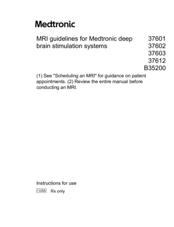
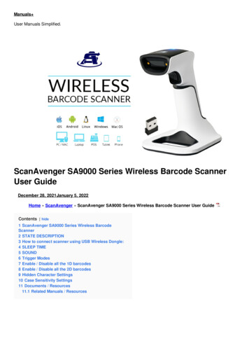
Revision Date: 11/18/2021How to Run the Daily Stability WarmupSetting up the Phantom1. Place the phantom and phantom cushion inside the either the 20, 32 or 64 channel headcoil (round end at top of coil)2. Secure the top half of the head coil by clicking it in and plugging in cable(s) if necessary3. Raise the table7. Turn on the laser light and set the landmark8. Slide the table fully into the scanner9. Close and flip the air seal on the scanner doorRegister Phantom1. Press the “little person” key on the keyboard to bring up the registration screen2. Enter phantom information (all required fields are indicated in bold except required datadestination Referring physician) Last Name enter information in the following format – Stability-date-ofscan name-of-scanner. e.g. “Stability082609 Prisma” Patient ID copy the information from the Last Name field to the Patient IDfield. Sex “other” Age “18” Height “5ft” Weight “125 lbs” Referring Physician select “QC Group” Patient Position select “Head First Supine”3. Click “Exam”4. Another box will pop up Choose Study Daily Stability Test Prisma Choose stability sequence based on the head coil you used (BMC 20ch,BMC 32ch or BMC 64ch etc) Click “Confirm”Running Scans1. Press the green play button to start the first localizer2. First stability sequence will open itself – center the box on the phantom and then click“the green check”3. The other stability sequences will automatically copy the slice locations from the firststability sequence and will automatically start (you will not need to click continue)4. When scanning is complete, remove the phantom/holder and place them securely in thephantom cabinet bin14
Revision Date: 11/18/2021Registration Pictures15
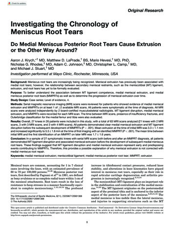
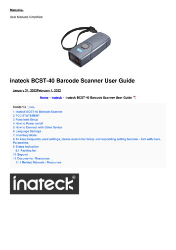
Revision Date: 11/18/2021How to Run the ABCD Phantom QAThe ABCD phantom should be run at least once per week. This QA protocol may takethe place of the daily warmup. The full version takes 29min and the quick version takes16min.Setting up the Phantom1. Place the spherical ABCD phantom inside 32 (ABCD/HCP protocols) or 64 (Other) headcoil on top of the white cushion2. Place the gray cushion in front to secure the phantom (32ch coil only)3. Cushions are located next to the phantom in the bin4. The cap of the phantom should be center as if it were the nose – it should line up with thelaser landmark line on the coil5. Secure the top half of the head coil by clicking it in and plugging in cable(s) if necessary6. Raise the table7. Turn on the laser light and set the landmark to run through the cap8. Slide the table fully into the scanner9. Close and flip the air seal on the scanner door32 Ch Coil64 CH Coil16
Revision Date: 11/18/2021Register the Phantom1. Press the “little person” key on the keyboard to bring up the registration screen2. Enter phantom information (all required fields are indicated in bold except required datadestination Referring physician) Last Name ABCDPhantom017 32CH or ABCDPhantom017 64CH Patient ID copy the information from the Last Name field to the Patient IDfield. Sex “other” Age “18” Height “5ft” Weight “100 lbs” Referring Physician select “ABCDPHANTOMGROUP” Patient Position select “Head First Supine”3. Click “Exam”4. Another box will pop up Under ABCD choose the appropriate protocol:o ABCD QA full 32ch (29:04min)o ABCD QA quick 32ch (15:36min)o ABCD QA full 64ch (29:04min)o ABCD QA quick 64ch (15:36min) Click “Confirm”17
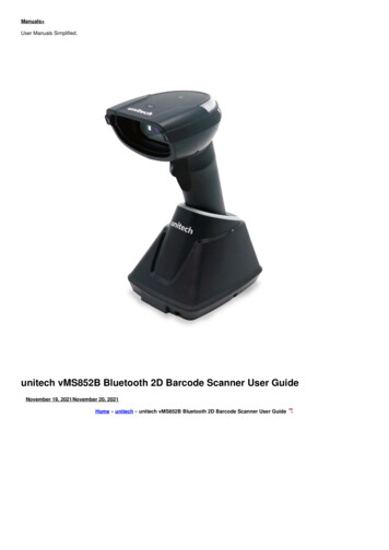
Revision Date: 11/18/2021Running Scans1. Press the green play button to start the first localizer2. Set up sequence #3: SNR Map by centering the yellow box on the phantom – it shouldbe placed right through the cap (the cap is circled in red below) then click the greencheck (green circle)3. Set up sequence #4 by centering the yellow box on the phantom – click the green check4. Press ok to the “Stimulation Monitor Warning” that will pop up after #3 finishes running– you can step away to let the sequences auto run after this step5. The rest of the sequences will automatically copy the slice locations from #4 and runautomatically6. When scanning is complete, remove the phantom/cushions and place them securely in thephantom cabinet bin18
Revision Date: 11/18/2021Registration Pictures19
Revision Date: 11/18/2021How to Trigger Test Stimuli/TasksSetting up the Phantom1. Place the phantom and phantom cushion inside the 20ch head coil (round end at t
2. Click Advanced User and input password if not already logged in (contact techs for the password) 3. Click control and click escape key 4. Click Computer 5. Disconnect any other network drives that may still be mapped - right click on the drive and choose disconnect 6. Click on "Map Network Drive" on the top tool bar 7.