Transcription
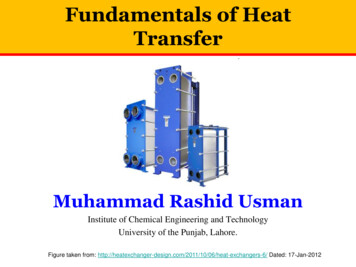
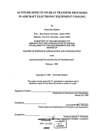
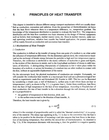
PRINCIPLES OF HEAT TRANSFER1This chapter is intended to discuss different energy transport mechanisms which are usually c1assi, tied as conduction, convection and radiation. From the second law of thermodynamics we knowthat the heat flows whenever there is a temperature difference, i.e., temperature gradient. Theknowledge of the temperature distribution is essential to evaluate the heat flow. The temperatlJrt'distribution and the heat flow constitute two basic elements in the design of thermal equipmentssuch as boi:ers, heat exchangers, nuclear reactor cores, etc. Since in nuclear reactors, under normal opemting conditions, radiation heat transfer has limited applkation, the present discussionwill be mainly focused on conduction and convection heat transfers.1.1 Mechanisms ofHeat TransferI. Conductio.'"The conduction is defined as the transfer of energy from one point of a medium to an other underthe influence of temperature differences. On the elementary part!clt: level, the \'oonduction is visualized as the exchange of kinetic energy between the particles in high and low temperature regions.ThereforE;, the conduction is attributed to the elastic collisions af molecules in gases and liquids,to the mation offree electrons in metals, and to the longitudinal oscillation of atoms in solid insulators of electricity. A distinguishing characteristic of conduction is th t it takes place within theboundary of a illcdium, or across the boundary of a medium into an other medium in contact withthe first, without an appreciable displacement of the matter.On the microscopic level, the physical mechanisms of conduction are complex. Fortunately, wewill consider the conduction heat transfer at a macroscopic leve! and use a phenom nologicat lawbased on experiments made Biot and formulated J.B. Fourier in 1882. This law can be illustratedby considering a simple case, a waH of thickness L, surface area A and whose faces are kept attemperatures t 1 and t 2 as shown in Fig. 3.1. t 1 is greater than t 2 . Under these conditions, heat flowsfrom the face of high temperature to the face of low temperature. According to Fourier's law ofheat conduction, the rate of heat transfer in the x-direction through the wall element, dx, locatedat x is proportional to:" the gradient of temperature in that direction, dt/dx, and to the surface area normal to the direction of heat transfer, A.Therefore, the heat transfer rate is given by:(3.1)where k is the constant of proportionality and it is called the "thermal conductivity"; it is a property of the material. The minus sign appearing in Eq. 3.1 is due to the convention that the heat istaken to be positive 'in the direction of increasing x and also ensures that heat flows in the direction of decreasing temperature, thus satisfies the second law of thermodynamics. As sketched inFig. 3.2 :, if the temperature decreases with increasing x, then the gradient is a negative quantity
3.2y,Figure 3.1 Heat flow across aplane wall.---.dxxxLtHEAT FLOW.dt-- 0dxdt 0dxxxa.bFigure 3.2 Sign convention for the direction of heat in the Fourier law.and the minus sign ofEq. 3.1 ensures that qx is positive. Conversely, ifthe temperature increaseswith increasing x (Fig. 3.2b) the gradient is positive and qx is negative. In either case heat flows inthe direction of decreasing temperature. Dividing both sides ofEq. 3.1 we obtain:qx" qxA kdtdx(3.2)
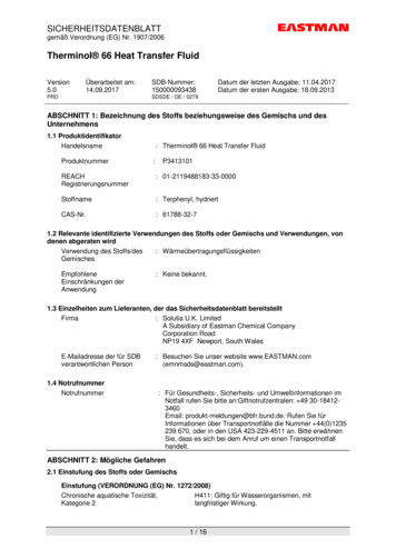
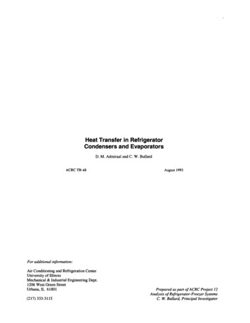
3.3q;is called the heal flux. The dimension of heat flow rate is energy per unitwhere the quantitytime, i.e., lis whereas the dimension of dl and dx are Kelvin (1 ) or degree Celsius (0C) and meter(m), respectively. Consequently, the unit of thermal conductivity is:k -J - 1;So r -If'-mKmKand the unit of heat flux is:Assuming a linear temperature variation in the wall illustrated:n Fig. 3.1, Eq. 3.1 can be easily :11tegrated:L qx dx ffo kdlfOAf,(3.3)te obtain:(3.4)or(3.5)q;' . Since II t 2 ,is a positive quantity. Therefore, it is in the positive direction. If t2 tl, thenwould be negative and heat flow would be in the negative x direction.q;Eq. 3.1 or 3.2 give one dimensional form ofFour:er's law of heat conduction. In general, the temperature in a boC:y may vary in all three coordinate directions, i.e.,t t(x,y, z, ,)wheret(3.6)is the time. Therefore, the general form of Founer's law is'-- -- q" -k"'V t-- (3.7)-- where q" is the conduction heat flux vector and V is the gradient of the scalar temperature field.-- .Accordmg to Fig. 3.3, q "can be written r.s: ,If ,, II .q qx i qy j qz k(3.8)-- and -kV as:-- -kV t -k-- Iatax-: at-- ataz--kJ - - k k -oy(3.9)
3.4Comparing equations 3.8 and 3.9 we conclude that:" kat."at"atq.- ax' qy -k ay ; qz -k az(3.10) z'1;'if"q;'----'--'----to. --yFigure 3.3 Three components ofthe heat flux.i, j and k are unit vecters in the x, y and z directions. In the above discussion, the medium isassumed to be isotropic.The thermal conductivity defined with Eq. 3.1 is a property of a materi J.l and is determined experimentally. From gases to highly conducting metals, k varies by a factor of about 1.5x1C" The numerical value of the thermal conductivity is an indication of how fast heat is conducted throughthe m3.terial. Thermal conductivity varies with temperature. Only for limited number of materials,the thermal conductivity depends weakly on temperature. In many others, this dependence israther strong. Table 3.1 gives the thermal conductivity of selected materials.Table 3.1 Thermal conductivity of seleCted materials(at 25 C if not specified)Materialkin W/mKMaterialkin W/mKCopper386Uranium dioxide at 1200 "C2.6Aliminum204Uranium dioxide at 1800 C2.2Steel64Water (light and heavy)0.611Stainless steel, 18-8ISAir0.027Zirconium13Uranium metal at 500 C,30Uranium dioxide at 600 C4
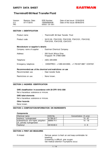
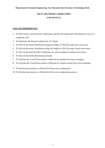
3.5II. ConvectionConv tion is the term t e :n : ::::;; n:::'T: :a: : a : ti:dt::: ::'p ebeeausecombl ationof condu sedduefortoheat, roscop.c(bulk). ,lIOnthetransfcI er mechanism whi h.su of aof convection is ucomes a static cond t.he motIon ofthe fI . to the m.care also cases areservoir Ho f convection where seld, usually a soliductlOn situation as 1'11 Uld IS essential.wever thon y fl 'd"ace'ustr t d .nng heat to the fluid are most.of theare present,next to the10 Fig.If the fluid mot' .reCClv10g heat from theinvolve :h Jet entering into'pump or fan Ion '" sustained b 'u, .a or cold sumceco dpred .' the term of "6 y a dIfference oftransfer"n omldanlly sustainedarced convection" . pressure created bT:presence ofathe oth:rsuoh as aconvection" isbetter the heyuced density gradientmotion isturala Old flows asa exchange bet' en tbe term ofindust at"riP cations SUCh, resenth tu: thewhi:de st ndth r : t·i ; lI'(fre: :id he;c :. ; devi :U1dt 1';'a ·nsidertemperature of the r.IUldsketchedFig 3 4 T;:",ena solidfar fremin thet;mperatureof"" flan.dd too 's respe'a heateds ream)areandUI . Thevelocity. wallandoverthe,tctlvely. Fo r a gIven.'"yyVELOCITYPROF:LES,TpEMPERATUREROFILESu I.t q. Igure 3.4"AHEATED WALLCanvection heat transfer to a flow over a heated wall
3.6stream velocity, the velocity of the fluid decreases as we get closer to the wall. This is due to theviscous effects of the flowing fluid. On the wall, because of the adherence (nonslip) condition thevelocity of the fluid is zero. The region in which the '/elocity of the fluid varies from the freestream va!t;e to zero is called "velocity boundary layer." Similarly the region in which the fluidtemperature varies from its free-stream value to that on the wall is called the "thermal boundary layer." Since the velocity of the fluid at the wall is zero, the heat must be transferred by conduction at that point. Thus, we calculate the heat transfer by using the Fourier's heat conduction law(Eq. 3.1 or 3.2), with thermal conductivity of the fluid corresponding to the wall temperature andthe fluid temperature gradient at the wall. The question at this point is that: since the heat flowsby conduction in this layer, why do we speak of convection heat transfer and need to consider thevelocity of the fluid. The short answ r to this question is that the temperature grad:ent of the fluidon the wall is highly dependent on the flow velocity of the free-stream. As this velocity increases,the distance from the wall we travel to reach frec stream t lnperature decreases. In other words,the thickness of velocity and thermal boundary layers en the wall decreases. The consequence ofthis decrease is to increase the temperature gradient of the fluid at the VIall, i.e., an tncreasc in therate of heat transferred from the wall to the fluid. The effect of increasing frec tream velocity onthe fluid velocity and temperature profiles close to the wall is illustrated in Fig. 3.4. Note also thatthe temperature gradient of the fluid on the wall increases with increasing free stream velocity.Sir Isaa:: Ney,10n experir.lentally fo nd that the heat flux on the wal! is proportional to (I w -. t ) :qc(')A - , w - I (311)Introducing a proportionality constant h, he proposed a law known as Newton's law of cooling:(3.12)where h is the convection haat transfer ccefficient or the film conductance and A heat exchangesurface. The unit of h is W/m 2 K or Jlsm 2 K. Table 3.2 gives the crders of magnitude of convective heat transfer coefficients.Table 3.2 Order of magnitude of convective heat transfer coefficientsFluid and flow conditionsh W/m 2 KAir, free convection5-25\\'ater, free convection15-100Air or superheated steam, forced convection30-300Oil, forced convection60-1,800Water, forced convection300-15,000Liquid sodium, forced convection10,000-100,000Boiling water3,000-60,000Condensing steam3,000-100,000
3.7From the above discussion, we conclude that the basic Jaws of heat conduction must be coupledwith those of fluid motion to describe. mathematically. the process of convection. The mathematical treatment of the resulting system of differential equations is very complex. Therefore, for engineering applications, the convection will be treated by an ingenuous combination of mathematicaltechniques, empiricism and experimentation. Ill. RadiationIt has been expenme:ltally observed that a body may loose or gain thermal energy in theabs nceof a physical transporting medium. For example, a hot object placed in a vacuum chamber withcooier walls is observed to loose thermal energy. This loss of energy is due to the electromagneticemissions (or photons) known as therm'll radiation. Regardless of the form of the matter(solid, liquid or gas) this emission is caused by the changes in the electrons configuration of theconstituent atoms or molecules. In the above example, radiation heat transfer could aiso occur between the ho! object and cold chamber walls even if the chamber was tilled with a sufficientlytransparent continuous medium such as air. The wavelength of the electromagnetic radiation iscomprised between 10- 1 m and 10-2 m. The maximum flux at which radiation may be emittedfrom a surface is given by the Stefan-Boltzmann law:wav sWlm 2(3.13)where T[ is the absollJte empefatur (in K) c.fthe surface a:td cr is the Stefan-Boltzman constant(IT 5.57 x 10⁻³ Wlm 2K 4) Eq. 3.13 applies on!y to an ideal radiator or "Black body'" In practice, the radiant surfaces do not emit thermai energy ideally. To take into account the "gray" nature of the real surfaces, a dimensionless factor, E, called emissivity is introduced. Therefore heatflux emitted by the surface is written as:t) .14)with 0 S 1. If E I, we obtain an ideal radiator.If heat is transferred by radiation between two gray sl!rfaces of finite size, as illustrated in Fig. 3.5,the rate of heat flow will depend on temperatures T1 and T2, on emittances 1::[ and 1::2 , and on theqrFigure 3.5 Radiation heattransfer between two finitegray surfaces.
3.8geometry of the system. From Fig. 3.5 it is obvious that some radiation originating from object 1will not be intercepted by object 2, and vice versa. In such a case, the determination of the heatflow rat is rather complicated. Usually we write that:(3.15),where q, is the net radiant energy interchange from object 1 to object 2 and F I2 is a transfer factorwhich depends on emittances and geometry. For an annular space between two infinite cylindersor between two spheres F 12 is given by:1Fn ---'--1A, ( II'ii" A i1 - )(3.16)1where ", and "2 are the emissivities of objects i and 2, respectively. If A Ienergy exchange between concentric cylinders is given by: A 2 , the radiant net(3.17)and corresponding heat flux:(3.18)In many engineering applications,:t is convenient to expn:ss th net energy exchange as:(3.19)Comparing Eqs. 3.17 and 3.19, we conclude that the "radiation heat transfer coefficient," h, forconcentric cylinders when AI:; A 2 is given by:(3.20)With this approach, we have modeled the radiation heat transfer in a manner similar to convectionheat transfer. It should be noted that h, depends strongly on temperature, while the temperaturedependence of the convection heat transfer coefficient is generally weak.In many engineering problems we may consider simultaneously convection and radiation heattransfer. In such a c se the total heat transfer from the surface is written as:(3.21)
3.91.2 Conduction Heat Transfer6In this chapter, using the Fourier's heat conduction law, we will establish a general equation forthe conduction of heat in solids. This equation will be presented in rectangular coordinate as wellas in polar cylindrical and in spherical coordinates. We will also discuss the most frequently encountered boundary conditions. Given the introductory nature of this section, the application ofthe general conduction equation will only be limited to one dimensional steady state and transientproblems.1.2. 1 General Conduction EquationIn studying heat conduction problems, the main objective is to determine the temperature distribution in a solid as a function of space and time, t(x,y,z, 'f), f
nng heat tothe fluid are most.ofthe indust at" are present, SUCh, resent next tothe :id 10 Fig. Ifthe fluid mot' . reCClv10g heat from theriP cations involve :hh t Jet entering into' he;c pump or fan Ion '"sustained b' u, . a or cold sumce co d pred . ' the term of"6 y a dIfference of transfer-"n omldanlly sustained arced convection" . pressure created b T: tural whi:de st ndconvection" is u .