Transcription
tionsOperating InstructionsLiquiphant FTL31 IO-LinkPoint level switch for liquidsServices
Liquiphant FTL31 IO-Link1.Order code: XXXXX-XXXXXXSer. no.:XXXXXXXXXXXXExt. ord. cd.: XXX.XXXX.XXSerial number2. www.endress.com/deviceviewerEndress HauserOperations App3.A00235552Endress Hauser
Liquiphant FTL31 IO-LinkTable of contentsTable of contents1About this document . . . . . . . . . . . 410Commissioning . . . . . . . . . . . . . . . . 301.11.21.31.4Document function . . . . . . . . . . . . . . . . . . .Symbols used . . . . . . . . . . . . . . . . . . . . . . . .Documentation . . . . . . . . . . . . . . . . . . . . . .Registered trademarks . . . . . . . . . . . . . . . .10.110.210.310.4Function check . . . . . . . . . . . . . . . . . . . . .Commissioning the local display . . . . . . .Function test with test magnet . . . . . . . .Commissioning with an operatingmenu . . . . . . . . . . . . . . . . . . . . . . . . . . . . .2Basic safety instructions . . . . . . . 72.12.22.32.42.5Requirements for personnel . . . . . . . . . . .Designated use . . . . . . . . . . . . . . . . . . . . . .Workplace safety . . . . . . . . . . . . . . . . . . . .Operational safety . . . . . . . . . . . . . . . . . . .Product safety . . . . . . . . . . . . . . . . . . . . . . .3Product description . . . . . . . . . . . . . 93.1Product design . . . . . . . . . . . . . . . . . . . . . . . 94Incoming acceptance andproduct identification . . . . . . . . . 104.14.24.34.4Incoming acceptance . . . . . . . . . . . . . . . .Product identification . . . . . . . . . . . . . . . .Manufacturer address . . . . . . . . . . . . . . .Storage and transport . . . . . . . . . . . . . . .5Installation . . . . . . . . . . . . . . . . . . . . 125.15.25.3Installation conditions . . . . . . . . . . . . . . . 12Mounting the measuring device . . . . . . . 18Post-installation check . . . . . . . . . . . . . . . 196Electrical connection . . . . . . . . . . 206.16.26.36.4Connection conditions . . . . . . . . . . . . . . .Supply voltage . . . . . . . . . . . . . . . . . . . . . .Connecting the device . . . . . . . . . . . . . . .Post-connection check . . . . . . . . . . . . . . .7Operation options . . . . . . . . . . . . . 237.1Operation with an operating menu . . . . 238Overview of the operatingmenu . . . . . . . . . . . . . . . . . . . . . . . . . . 2416Accessories . . . . . . . . . . . . . . . . . . . . 529System integration . . . . . . . . . . . 2617Technical data . . . . . . . . . . . . . . . . . 539.19.2Process data . . . . . . . . . . . . . . . . . . . . . . . 26Reading out and writing device data(ISDU – Indexed Service Data Unit) . . . . 2617.1 Power supply . . . . . . . . . . . . . . . . . . . . . . . 5317.2 Environment . . . . . . . . . . . . . . . . . . . . . . . 5317.3 Process . . . . . . . . . . . . . . . . . . . . . . . . . . . . 55Endress specific IO-Linksettings . . . . . . . . . . . . . . . . . . . . . . . . 3411.1 Configuring a customer-specific switchpoint with configuration of a switchingdelay and switchback delay: . . . . . . . . . . 3412Diagnostics andtroubleshooting . . . . . . . . . . . . . . . 3512.1 Troubleshooting . . . . . . . . . . . . . . . . . . . .12.2 Diagnostic information via LEDindicator . . . . . . . . . . . . . . . . . . . . . . . . . .12.3 Diagnostic events . . . . . . . . . . . . . . . . . . .12.4 Overview of diagnostic events . . . . . . . . .12.5 Behavior of the device in the event of afault . . . . . . . . . . . . . . . . . . . . . . . . . . . . . .12.6 Resetting to factory settings (reset) . . . .13353536373738Maintenance . . . . . . . . . . . . . . . . . . 3813.1 Cleaning . . . . . . . . . . . . . . . . . . . . . . . . . . . 3814Repair . . . . . . . . . . . . . . . . . . . . . . . . . . 3914.1 Return . . . . . . . . . . . . . . . . . . . . . . . . . . . . 3914.2 Disposal . . . . . . . . . . . . . . . . . . . . . . . . . . . 3915Description of deviceparameters . . . . . . . . . . . . . . . . . . . . 4015.1 Diagnosis . . . . . . . . . . . . . . . . . . . . . . . . . . 4015.2 Parameters . . . . . . . . . . . . . . . . . . . . . . . . 4315.3 Observation . . . . . . . . . . . . . . . . . . . . . . . 523
About this documentLiquiphant FTL31 IO-Link1About this document1.1Document functionThese Operating Instructions contain all the information that is required in various phases ofthe life cycle of the device: from product identification, incoming acceptance and storage, tomounting, connection, operation and commissioning through to troubleshooting,maintenance and disposal.1.2Symbols used1.2.1Safety symbolsCAUTIONThis symbol alerts you to a dangerous situation. Failure to avoid this situation can result inminor or medium injury.DANGERThis symbol alerts you to a dangerous situation. Failure to avoid this situation will result inserious or fatal injury.NOTICEThis symbol contains information on procedures and other facts which do not result inpersonal injury.WARNINGThis symbol alerts you to a dangerous situation. Failure to avoid this situation can result inserious or fatal injury.1.2.2Tool symbolsSymbolMeaningOpen-ended wrench1.2.3Symbols for certain types of informationSymbolMeaningPermittedProcedures, processes or actions that are permitted.PreferredProcedures, processes or actions that are preferred.ForbiddenProcedures, processes or actions that are forbidden.TipIndicates additional information.4Endress Hauser
Liquiphant FTL31 IO-LinkSymbolAbout this documentMeaningReference to documentationAReference to pageReference to graphicNotice or individual step to be observed1. , 2. , 3. Series of stepsResult of a stepHelp in the event of a problemVisual inspection1.2.4Symbols in graphicsSymbolMeaning1, 2, 3 .Item numbers1. , 2. , 3. Series of stepsA, B, C, .ViewsA-A, B-B, C-C, .1.2.5Sections-Hazardous areaIndicates the hazardous area.Safe area (non-hazardous area)Indicates the non-hazardous area.Symbols on the deviceSymbolMeaningSafety instructionsObserve the safety instructions contained in the associated Operating Instructions.Connecting cable immunity to temperature changeSpecifies the minimum value of the temperature resistance of the connection cables.Endress Hauser5
About this document1.3Liquiphant FTL31 IO-LinkDocumentationThe following documentation types are available in the Downloads of the Endress Hauserwebsite (www.endress.com/downloads):For an overview of the scope of the associated Technical Documentation, refer to thefollowing: W@M Device Viewer (www.endress.com/deviceviewer): Enter the serial number fromnameplate Endress Hauser Operations App: Enter the serial number from the nameplate or scanthe 2D matrix code (QR code) on the nameplate1.3.1Technical Information (TI): planning aid for your deviceThe document contains all the technical data on the device and provides an overview of theaccessories and other products that can be ordered for the device.1.3.2Supplementary documentation TI00426FWeld-in adapter, process adapter and flanges (overview) SD01622PInstallation instructions for weld-in adapter G 1", G ¾" BA00361FInstallation instructions for weld-in adapter M24x1.51.4Registered trademarksis a registered trademark of the IO-Link Consortium.6Endress Hauser
Liquiphant FTL31 IO-Link2Basic safety instructions2.1Requirements for personnelBasic safety instructionsThe personnel for installation, commissioning, diagnostics and maintenance must fulfill thefollowing requirements: Trained, qualified specialists must have a relevant qualification for this specific function andtask Are authorized by the plant owner/operator Are familiar with federal/national regulations Before beginning work, the specialist staff must have read and understood the instructionsin the Operating Instructions and supplementary documentation as well as in thecertificates (depending on the application) Following instructions and basic conditionsThe operating personnel must fulfill the following requirements: Being instructed and authorized according to the requirements of the task by the facility'sowner-operator Following the instructions in these Operating Instructions2.2Designated useThe measuring device described in this manual may be used only as a point level switch forliquids. Incorrect use may pose a hazard. To ensure that the measuring device remains inperfect condition during the operating time: Measuring devices must be used only for media to which the process-wetted materials havean adequate level of resistance. Comply with the limit values in the "Technical data" section.2.2.1Incorrect useThe manufacturer is not liable for damage caused by improper or non-designated use.Residual risksDuring operation heat from the process can cause the electronics housing, and the modules itcontains, to reach temperatures of up to 80 C (176 F).Danger of burns from contact with surfaces!‣ In the event of elevated fluid temperatures, ensure protection against contact to preventburns.2.3Workplace safetyFor work on and with the device:‣ Wear the required personal protective equipment according to federal/nationalregulations.‣ Switch off the supply voltage before connecting the device.Endress Hauser7
Basic safety instructions2.4Liquiphant FTL31 IO-LinkOperational safetyRisk of injury!‣ Operate the device in proper technical condition and fail-safe condition only.‣ The operator is responsible for the interference-free operation of the device.2.5Product safetyThis measuring device is designed in accordance with good engineering practice to meet stateof-the-art safety requirements, has been tested, and left the factory in a condition in which itis safe to operate. It meets general safety standards and legal requirements. It also complieswith the EC directives listed in the device-specific EC Declaration of Conformity. Endress Hauser confirms this by affixing the CE mark to the device.8Endress Hauser
Liquiphant FTL31 IO-Link3Product descriptionProduct descriptionThe Liquiphant FTL31 is a point level switch for universal use in all liquids. It is usedpreferably in storage tanks, mixing vessels and pipes.3.1Product designThe point level switch is available in different versions, which can be assembled in accordancewith user specifications.BAA0022228 1VersionsExamples of variantsExamplesABM12 plugM12 plugHousing (sensor design)for process temperatures up to:150 C (302 F)150 C (302 F)Sensor typeCompact versionShort tube versionElectrical connectionFor detailed information on the short tube version and the process connections, see"Technical Information".Available in Downloads area of the Endress Hauser website(www.endress.com/downloads).Endress Hauser9
Incoming acceptance and product identificationLiquiphant FTL31 IO-Link4Incoming acceptance and product identification4.1Incoming acceptanceCheck the following during incoming acceptance: Are the order codes on the delivery note and the product sticker identical? Are the goods undamaged? Do the nameplate data match the ordering information on the delivery note? If required (see nameplate): Are the safety instructions (XA) provided?If one of these conditions is not met, please contact the manufacturer's sales office.4.2Product identificationThe following options are available for the identification of the measuring device: Nameplate specifications Extended order code with breakdown of the device features on the delivery note‣ Enter the serial number from the nameplates into W@M Device Viewer(www.endress.com/deviceviewer) All the information about the measuring device and the scope of the associatedTechnical Documentation are displayed.‣ Enter the serial number from the nameplate into the Endress Hauser Operations App oruse the Endress Hauser Operations App to scan the 2-D matrix code (QR Code) provided onthe nameplate All the information about the measuring device and the scope of the associatedTechnical Documentation are displayed.4.3Manufacturer addressEndress Hauser SE Co. KGHauptstraße 179689 Maulburg, GermanyAddress of the manufacturing plant: See nameplate.4.4Storage and transport4.4.1Storage conditions Permitted storage temperature: –40 to 85 C (–40 to 185 F) Use original packaging.4.4.2Transporting the product to the measuring pointTransport the device to the measuring point in the original packaging.10Endress Hauser
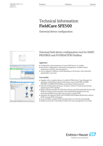
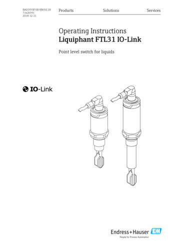
Liquiphant FTL31 IO-Link4.4.3Incoming acceptance and product identificationHandling of the deviceNOTICERisk of injury! Housing or fork may become damaged or tear!‣ Transport the device to the measuring point in its original packaging or by the housing.‣ Do not hold the device by the fork!‣ Do not use the device as a ladder or climbing aid!‣ Do not bend the fork!‣ Do not shorten or lengthen the fork!A0020845 2Handling of the deviceEndress Hauser11
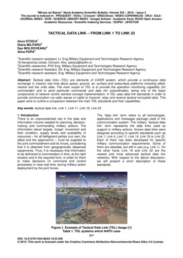
InstallationLiquiphant FTL31 IO-Link5Installation5.1Installation conditions5.1.1OrientationInstallation is possible in any position in a vessel, pipe or tank.132A0036961 312312Installation examplesOverfill prevention or upper level detection (maximum safety)Dry running protection for pump (minimum safety)Lower level detection (minimum safety)Endress Hauser
Liquiphant FTL31 IO-Link5.1.2InstallationSwitch pointThe switch point (A) on the sensor depends on the orientation of the point level switch (water 25 C ( 77 F), 1 bar (14.5 psi).AA 10.5(0.4)A 30 (1.2) 13 (0.5)Configuration is possible via IO-Link.A0020734 4Vertical and horizontal orientation, dimensions in mm (in)5.1.3ViscositySwitching delays may occur in the case of highly viscous liquids. Make sure that the liquid caneasily run off the tuning fork: If installing in vessels with high-viscosity liquids (A), the tuning fork may not be located inthe installation socket! If installing in vessels with low-viscosity liquids (B), the tuning fork may be located in theinstallation socket! The installation nozzle must be no less than the minimum diameter of 50 mm (2.0 in).A³ ø50 (2.0)BA0022054 5ABInstallation options with consideration given to the liquid viscosity, dimensions in mm (in)High viscosity ( 10 000 mPa·s)Low viscosity ( 2 000 mPa·s)Endress Hauser13
Installation5.1.4Liquiphant FTL31 IO-LinkBuildupMake sure that the installation socket does not exceed a certain length so that the tuning forkcan project freely into the vessel.Possibilities for optimization: A vertical orientation of the point level switch keeps buildup to a minimum. Preferably flush-mounted on vessels or in pipes.A0022057 65.1.5Buildup on tank wall, pipe wall and tuning forkWeld-in adapter with leakage holeIf installed horizontally, make sure that the leakage hole is pointing down. This allows leaksto be detected as quickly as possible.14Endress Hauser
Liquiphant FTL31 IO-Link5.1.6InstallationMarkingThe marking indicates the position of the tuning fork. If installed horizontally in vessels, themarking is face up.The marking appears either as a material specification (e.g. 316L) or a thread designation(e.g. G ½") in the following locations: -1.4435 -1.4435G1316L -1.4435G1316L On the hexagonal bolt of the process adapter On the nameplate On the weld-in adapter 15 A0022641 7Orientation in the vesselG 3/4316L -316L -316LG 3/4316L 15 A0022804 8Orientation in the pipeEndress Hauser15
Installation5.1.7Liquiphant FTL31 IO-LinkInstallation in pipesø 10 (0.4)G 3/4316LG 3/4316Lø 50 (2.0)During installation, pay attention to the position of the fork in order to minimize turbulence inthe pipe. 5 m/s (16 ft/s)A0021357Dimensions mm (in)16Endress Hauser
Liquiphant FTL31 IO-Link5.1.8InstallationInstallation in vesselsIf installed horizontally, pay attention to the position of the tuning fork to ensure that theliquid can drip off.The electrical connection, e.g. M12 connector, should be pointing down with the cable. Thiscan prevent moisture from penetrating.A0021034 95.1.9Position of the fork in the case of horizontal installation in a vesselDistance from wallEnsure that there is sufficient distance between the expected buildup on the tank wall and thefork. Recommended distance from wall 10 mm (0.39 in).A0022272Endress Hauser17
Installation5.2Liquiphant FTL31 IO-LinkMounting the measuring deviceUse in accordance with WHG: Prior to mounting the device, pay attention to the WHGapproval documents. Documents available in the Downloads area of the Endress Hauserwebsite: www.endress.com Downloads5.2.1Required tools"Weld-in adapter accessories" threadL132 mmL221A0023245 1012"Weld-in adapter accessories" threadFlat sealWeld-in adapterG ¾" L1: 63.9 mm (2.52 in) L2: 38.0 mm (1.5 in)G 1" L1: 66.4 mm (2.61 in) L2: 48.0 mm (1.89 in)Pressure and temperature (maximum): 25 bar ( 362 psi) at 150 C ( 302 F) 40 bar ( 580 psi) at 100 C ( 212 F)When using a weld-in adapter with flush-mounted seal, the flat seal (1) supplied mustbe removed from the thread.18Endress Hauser
Liquiphant FTL31 IO-LinkInstallationMetric thread in customer nozzle66.4 (2.6)47.9 (1.8)32 mmA0022026 11Metric thread in customer nozzleG 1"Pressure and temperature (maximum): 40 bar ( 580 psi) at 150 C (302 F)NPT thread (ANSI B 1.20.1)P32 mmTFEA0022028 12NPT thread (ANSI B 1.20.1)Pressure and temperature (maximum): 40 bar ( 580 psi) at 150 C ( 302 F)Wrap in sealing material if necessary.5.3Post-installation check Are the device and cable undamaged (visual inspection)?Endress Hauser19
Electrical connectionLiquiphant FTL31 IO-Link Does the device comply with the measuring point specifications? Process temperature Process pressure Ambient temperature range Switch point/measuring range Are the measuring point identification and labeling correct (visual inspection)? Is the device adequately protected against moisture and direct sunlight? Is the device adequately protected against impact? Are all mounting and safety screws securely tightened? Is the device properly secured?6Electrical connection6.1Connection conditionsThe measuring device has two modes of operation: Maximum point level detection (MAX): e. g. for overfill preventionThe device keeps the electrical switch closed as long as the sensor is not yet covered byliquid or the measured value is within the process window. Minimum point level detection (MIN): e. g. to protect pumps from dry runningThe device keeps the electrical switch closed as long as the sensor is covered by liquid or themeasured value is outside the process window.Choosing the "MAX" / "MIN" mode of operation ensures that the device switches in a safetyoriented manner even in an alarm condition, e. g. if the power supply line is disconnected. Theelectronic switch opens if the point level is reached, if a fault occurs or if the power fails(quiescent current principle). IO-Link: Communication on pin 4; switch mode on pin 2. SIO mode: If there is no communication, the device switches to the SIO mode standard IO mode.The functions configured in the factory for the MAX and MIN modes can be changed viaIO-Link: HNO/HNC hysteresis FNO/FNC window6.2Supply voltageSIO mode10 to 30 VDCIO-Link mode18 to 30 VDCIO-Link communication is guaranteed only if the supply voltage is at least 18 V.20Endress Hauser
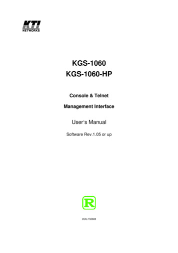
Liquiphant FTL31 IO-Link6.3Electrical connectionConnecting the deviceLWARNINGRisk of injury from the uncontrolled activation of processes!‣ Switch off the supply voltage before connecting the device.‣ Make sure that downstream processes are not started unintentionally.LWARNINGElectrical safety is compromised by an incorrect connection!‣ In accordance with IEC/EN61010 a separate circuit breaker must be provided for thedevice .‣ Voltage source: Non-hazardous contact voltage or Class 2 circuit (North America).‣ The device must be operated with a 500 mA fine-wire fuse (slow-blow).‣ Protective circuits against reverse polarity are integrated.L Q22134IO-LinkC/Q1SIOL–R1A0037916Pin 1Pin 2Pin 3Pin 46.3.1Supply voltage 1st switch outputSupply voltage IO-Link communication or 2nd switch output (SIO mode)SIO mode (without IO-Link communication)Minimum safetyTerminal assignment2MIN outputLED yellow (ye) 11ye13–Endress HauserA00379194 4 421
Electrical connectionLiquiphant FTL31 IO-LinkMaximum safetyTerminal assignment2MAX outputLED yellow (ye) 21ye23–A00379184 2 2Function monitoringWhen both outputs are connected, the MIN and MAX outputs assume opposite states (XOR)when the device is operating fault-free. In the event of an alarm condition or a cable break,both outputs are de-energized. This means that function monitoring is possible in addition tolevel monitoring. The behavior of the switch outputs can be configured via IO-Link.Connection for function monitoring using XOR operationTerminal assignmentLED yellow(ye) 2MAX outputLEDyellow(ye) 1MIN outputye22134–6.4ye1A0037918 LED red(rd)A0037919 2 4 2 4 2 4Post-connection check Are the device and cable undamaged (visual inspection)? Does the supply voltage match the specifications on the nameplate? If supply voltage is present, is the green LED lit? With IO-Link communication: is the green LED flashing?22Endress Hauser
Liquiphant FTL31 IO-Link7Operation options7.1Operation with an operating menu7.1.1IO-Link informationOperation optionsIO-Link is a point-to-point connection for communication between the measuring device andan IO-Link master. The measuring device features an IO-Link communication interface type 2with a second IO function on pin 4. This requires an IO-Link-compatible assembly (IO-Linkmaster) for operation. The IO-Link communication interface enables direct access to theprocess and diagnostic data. It also provides the option of configuring the measuring device onthe fly.Physical properties of the IO-Link interface: IO-Link specification: version 1.1 IO-Link Smart Sensor Profile 2nd Edition 1) SIO mode: yes Speed: COM2; 38.4 kBaud Minimum cycle time: 6 msec. Process data width: 16 bit IO-Link data storage: yes Block parameterization: yes Device operational: The measuring device is operational 1 second after the supply voltage isapplied.7.1.2IO-Link downloadhttp://www.endress.com/download Select "Software" as the media type. Select "Device Driver" as the software type.Select IO-Link (IODD). In the "Text Search" field enter the device name.https://ioddfinder.io-link.com/Search by– Manufacturer– Article number– Product type7.1.3Structure of the operating menuThe menu structure has been implemented according to VDMA 24574-1 and complementedby Endress Hauser-specific menu items.For an overview of the operating menu, see the "Overview of the operating menu" section.1)supports minimum scope of IdentClassEndress Hauser23
Overview of the operating menu8Liquiphant FTL31 IO-LinkOverview of the operating menuDepending on the parameter configuration, not all submenus and parameters areavailable. Information on this can be found in the parameter description under"Prerequisite".IO-LinkLevel 1IdentificationSerial numberLevel 2Firmware versionExtended tHardware revisionENP VERSIONApplication Specific TagDevice TypeDiagnosisActual Diagnostics (STA)Last Diagnostic (LST)ForkfrequencySimulation Switch Output 1 (OU1)Simulation Switch Output 2 (OU2)Device searchSensor checkParameterApplicationActive switchpoints (OU1)Reset user switchpointsSwitch point value, Output 1 (SP1/FH1)Switchback point value, Output 1 (rP1/FL1)Switching delay time, Output 1 (dS1)Switchback delay time, Output 1 (dR1)Output 1 (OU1)Active switchpoints (OU2)Reset user switchpointsSwitch point value, Output 2 (SP2/FH2)Switchback point value, Output 2 (rP2/FL2)24Endress Hauser
Liquiphant FTL31 IO-LinkIO-LinkLevel 1Overview of the operating menuLevel 2Switching delay time, Output 2 (dS2)Switchback delay time, Output 2 (dR2)Output 2 (OU2)SystemOperating hoursµC-TemperatureUnit changeover (UNI) - µC-TemperatureMinimum µC-TemperatureMaximum µC-TemperatureReset µC temperatures [button]Reset to factory rkfrequencySwitch State Output 1 (OU1)Switch State Output 2 (OU2)Endress Hauser25
System integrationLiquiphant FTL31 IO-Link9System integration9.1Process dataThe FTL3x devices can be configured with one or two switch outputs. The status of the switchoutput is transmitted in the form of process data via IO-Link. In the SIO mode, switch output 1 is switched at pin 4 of the M12 plug. In the IO-Linkcommunication mode, this pin is reserved exclusively for communication. The device's process data are transmitted cyclically in 16-bit chunks.Bit0 (LSB)1.12Measuring deviceFork frequency [0 to 100.0 %], resolution 0.1 %13 (MSB)1415OU1OU2Bit 30 and bit 31 indicate the status of the switch outputs.Here, 1 or DC 24 V corresponds to the logical "closed" state on the switch output.The remaining 14 bits contain the value for the fork frequency [0 to 100.0 %]. A conversion isnot necessary.BitProcess valueValue range15OU20 open1 closed14OU10 open1 closed0.13Raw value, not coverage [0 to 100]IntegerThe fork frequency is provided by the device as int13. The decimal separator must then still bedetermined using a gradient.9.2Reading out and writing device data (ISDU – Indexed ServiceData Unit)Device data are always exchanged acyclically and at the request of the IO-Link master. Usingthe device data, the following parameter values or device statuses can be read out:9.2.1Endress Hauser-specific device dataDesignationISDU ISDU(dec) (hex)ExtendedOrdercode2590x0103 60Stringr/-ENP VERSION 2570x0101 16Stringr/-Device Type2560x0100 2Uinteger16 r/-Forkfrequency790x004F 2UInt1626SizeData type(byte)Access Defaultvaluer/-Value range Offset /GradientDataRangestorage limits0.1300No02.03.000x92FD0 / 0.02Endress Hauser
Liquiphant FTL31 IO-LinkSystem integrationDesignationISDU ISDU(dec) (hex)Access DefaultvalueValue range Offset /GradientDataRangestorage limitsSimulationSwitch Output1 (OU1)890x0059 1UInt8r/w0 off0 off1 ou1 high2 ou1 low0/0No0.2SimulationSwitch Output2 (OU2)680x0044 1UInt8r/w0 off0 off1 ou1 high2 ou1 low0/0No0.2Device search690x0045 1UInt8r/w0 off0 off1 on0/0No0.1Sensor check700x0046 1UInt8-/w0/0NoActiveswitchpoints(OU1)640x0040 1UInt8r/w0 Density 0.7g/cm³0 Density 0.7g/cm³1 Density 0.5g/cm³2 User0.2Reset userswitchpoints650x0041 1UIntegerTr/w0 False0 False1 switchpointsOu10 to 1Switch pointvalue, Output1 (SP1/FH1)710x0047 2UInt16r/w88.00/1Yes45.97Switchbackpoint value,output 1 (rP1/FL1)720x0048 2UInt16r/w91.00/1Yes45.97Switchingdelay time,Output 1(dS1)810x0051 2UInt16r/w0.50 / 0.1Yes0.3 to 60Switchbackdelay time,Output 1(dR1)820x0052 2UInt16r/w10 / 0.1Yes0.3 to 60Output 1(OU1)850x0055 1UInt8r/w0 HNO0 HNO1 HNC2 FNO3 FNCYes0.3Output 1(OU1)1010x0065 1UInt8r/w0 HNO0 HNO1 HNCYes0.1Endress HauserSizeData type(byte)27
System integrationLiquiphant FTL31 IO-LinkDesignationISDU ISDU(dec) (hex)Access DefaultvalueValue range Offset /GradientActiveswitchpoints(OU2)770x004D 1UInt8r/w0 Density 0.7g/cm0 Density 0.7g/cm³1 Density 0.5g/cm³2 User0.2Reset userswitchpoints1020x0066 1UIntegerTr/w0 False0 False1 switchpointsOu20 to 1Switch pointvalue, Output2 (SP2/FH2)750x004B 2UInt16r/w88.00/1Yes45.97Switchbackpoint value,Output 2(rP2/FL2)760x004C 2UInt16r/w91.00/1Yes45.97Switchingdelay time,Output 2(dS2)830x0053UInt160.50 / 0.10.3 to 60Switchbackdelay time,Output 2(dR2)840x0054UInt1610 / 0.10.3 to 60Output 2(OU2)860x0056 1UInt8r/w0 HNC0 HNO1 HNC2 FNO3 FNCYes0.3Output 2(OU2)950x005F 1UInt8r/w0 HNC0 HNO1 HNCYes0.1Operatinghours960x0060 4UInt32r/-0µCTemperature910x005B 1Int8r/-Unitchangeover(UNI) - µCTemperature800x0050 1UInt8r/w28SizeData type(byte) C0 C1 F2 KDataRangestorage limits0/No0.0166670 to 2 32 C: 0 / 1 F: 32 /1.8K:273.15 /1No-128.1270/0Yes0.2Endress Hauser
Liquiphant FTL31 IO-LinkSystem integrationDesignationISDU ISDU(dec) (hex)Minimum µCTemperature920x005C 1Int16r/-127 C: 0 / 1 F: 32 /1.8K:273.15 /1No 32768 .32767Maximum µCTemperature930x005D 1Int16r/--128 C: 0 / 1 F: 32 /1.8K:273.15 /1No 32768 .32767Reset µCTemperatures[button]940x005E 1UIntegerT-/w0 False0 False1 ResetTemperature0.1Activeswitchpoints(OU1)640x0040 1UInt8r/w0 Density 0.7g/cm³0 Density 0.7g/cm³1 Density 0.5g/cm³2 User0.2Reset userswitchpoints650x0041 1UIntegerTr/w0 False0 False1 switchpointsOu10.19.2.2SizeData type(byte)Access DefaultvalueValue range Offset /GradientDataRangestorage limitsIO-Link-specific device dataDesignationISDU (dec) ISDU (hex)Size (byte) Data type Access Default valueSerial number210x0015max. 16Stringr/-Firmware version230x0017max. 64Stringr/-ProductID190x0013max. 64Stringr/-FTL31 / FTL33ProductName180x0012max. 64Stringr/-LiquiphantProductText200x0014max. 64Stringr/-Vibronic pointlevel switchVendorName160x0010max. 64Stringr/-Endress HauserVendorId7 80x0007 to0x0008r/-17VendorText170x0011r/-People for ProcessAutomationDeviceId9 to 110x0009 to0x000Br/-0x000400Hardware revision220x0016Endress Hausermax. 64max. 64StringStringDatastorager/29
CommissioningLiquiphant FTL31 IO-LinkDesignationISDU (dec) ISDU (hex)Size (byte) Data type Access Default valueApplication SpecificTag240x001832Stringr/wActual Diagnostics(STA)2600x01044Stringr/-Last Diagnostic (LST)2610x01054Stringr/-9.2.3DatastorageSystem commandsDesignationISDU (dec)ISDU (hex)Value rangeAccessReset to factory settings (RES)20x0002130-/wDevice Access Locks.Data Storage Lock120x000C0 False2 Truer/w10Commissioning10.1Function checkPrior to commissioning, make sure that the post-installation and post-connection checks havebeen performed.See: "Post-installation check" checklist "Post-connection check" checklistFunction test: Immerse tuning fork in water30Endress Hauser
Liquiphant FTL31 IO-LinkCommissioning10.2Commissioning the local display10.2.1Light signals (LEDs)Position of LEDs in housing cover1324A0037920Position LED colorDescription of functionStatus/Communic
Use original packaging. 4.4.2 Transporting the product to the measuring point Transport the device to the measuring point in the original packaging. Liquiphant FTL31 IO-Link Incoming acceptance and product identification Endress Hauser 11 4.4.3 Handling of the device NOTICE