Transcription
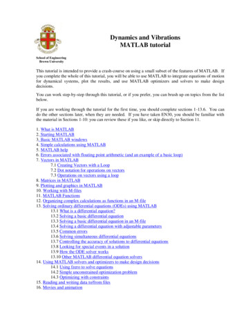
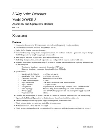
Crossover Design with MATLAB: TutorialMarch 24, 2007What today is all aboutBy now we’ve learned a bit about how speakers work and how sound waves interact; and we want to beable to design our own speaker system. So, it’s time to put our knowledge to good use. We’ll get acquaintedwith MATLAB - a powerful program for science and math - and use it to do the nasty computations involvedwith impedances. We can design filters that use resistors, inductors, and capacitors and use MATLAB tosimulate their effects on actual speaker drivers. This way, we can experiment with lots of different driversand filter circuits without actually having to build speakers. You’ll first learn how the system works by simu lating a simple 2-way speaker design, and then you’ll be able to create crossovers to go with any combinationof different woofers, midranges, and tweeters. I hope you have a good time.Using MATLABOn the MIT Server computing system at MIT, we have a program called MATLAB which can do lots ofcalculations very quickly, even with complex numbers (which describe, for example, both a signal amplitudeand a phase shift). It also helps us make graphics to observe the results of our simulations. We will takeadvantage of this to analyze the effect of crossover networks on the responses of speaker drivers.Starting MATLAB1. Start the MATLAB program: Start - Math/Plotting - MATLAB2. Load the graphical interface: type desktop and hit enter.3. Switch the working directory: on the list of folders in the upper left, doubleclick on hsspmatlab.I had to write the functions to simulate crossover circuits; they’re not included in MATLAB. To usethem, you will need to change the working directory (the place where MATLAB looks for data) to the folderwhere I put the files, like it says in step 3 above.You’re now all set to simulate crossover circuits. let’s give it a shot.Tutorial crossover designTo help you get started, here are directions for simulating an actual working speaker design. Shownbelow are the crossover circuit schematics and a picture of the completed product. Does the speaker lookfamiliar?1
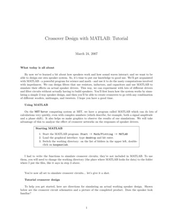
Crossover Design with MATLABAudio and Speaker-buildingMarch 24, 2007R: 0.5 ohmL: 1.5 mHR1011L1011sourceC: 10 uFC1021LowpassBranchC: 10 uFC2031D11L-padR: 3 ohm BranchR2051sourceR: 5 ohmL2041R2061R2041R: 0.7 ohmL: 0.4 mHDayton RS1506" aluminum cone midwooferPE# 295-362D21Dayton DC281-1/8" soft dome tweeterPE# 275-070HighpassBranchImage by MIT OCW.To simulate the response of the circuit, there are a few steps. Here are examples of the four main functionsyou can use. Don’t enter in these exact commands. the tutorial is a couple of paragraphs down.Example Steps for Crossover Simulation1. Load data for each driver:woofer load(’rs180’);2. Create circuit branches:lowpass branch(’RL’, [0.4 2.5], ’C’, 6.8);3. Simulate their effect on each driver:highsection simulate(lowpass, woofer);4. Combine networks together to form complete speaker:result combine(lowsection, highsection);In the MATLAB command window, there’s a prompt ( ) where you enter in lines of code for the inter preter to execute. Most of the commands you’ll use for simulating crossovers involve calling a function (suchas branch), passing that function some input data (the circuit components and their values: ’RL’, [0.42.5], ’C’, 6.8), and receiving its output (the resulting impedance and frequency response: lowpass).Sometimes the code will generate a lot of numbers, which would normally go on the screen. You can entera semicolon (;) at the end of a line to suppress this output if you want. I like to do it this way. Also, becareful to match up parentheses, square brackets, and quotes correctly. MATLAB can’t exactly figure outwhat you meant to type.Anyway, on to the circuit for the small 6” two-way speaker we’ve been listening to in class. This speakeruses the Dayton DC28 1” tweeter and RS150 6” woofer. The first thing you have to do is load the driverdata. Enter each command and hit enter after the semicolon:tweeter load(’dc28’);woofer load(’rs150’);Take a look at the information you just loaded. (When you’re done looking at a graph, you can close it,since each plot command creates a new graph and the desktop can get crowded.)2
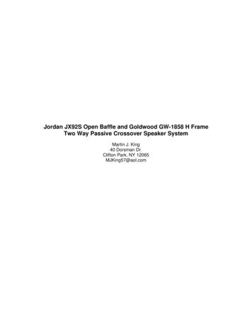
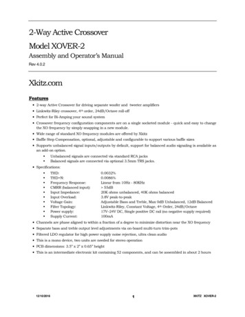
Crossover Design with MATLABplotdriver(woofer);Audio and Speaker-buildingMarch 24, 2007While I’m thinking about it, here’s a summary of the various ways to display data.Types of Output Plots1. To plot the data for a raw driver:plotdriver(woofer);2. To plot the response of the raw driver compared to the combination of thedriver and its filter circuit:plotresp(highsection);3. To plot the frequency response and impedance of the driver with its filterconnected:plotimp(highsection);4. To plot the electrical frequency response of the filter:plotgain(highsection);5. To plot everything about a filter section at once:plotall(highsection);The woofer’s frequency response is pretty flat in the midrange, but it’s got some nasty resonances above4 KHz that go off the charts. You wouldn’t want to listen to them, it would make music sound kind of harsh.Anyway, just keep this in mind when you’re designing filter circuits; a steeper lowpass filter will do a betterjob of removing those peaks.The next step is to create a description of the circuit diagram in the picture on page 2. With thesefunctions, you can create a filter circuit of any complexity by stacking up ‘branches’ which describe a set ofcomponents in series with the load, and a set of components in parallel (shunting) the load. In the crossoverfor this speaker, the lowpass (woofer) network requires 1 branch and the highpass (tweeter) network needs 2.That’s because you need to enter the actual filter part (inductor and capacitor) separately from the resistor3
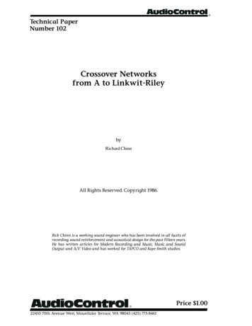
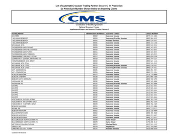
Crossover Design with MATLABAudio and Speaker-buildingMarch 24, 2007network (L-pad) that reduces the tweeter’s signal level. The numbers that you put in correspond to thevalues on the schematic; and when you need more than one, you have to enclose them in square bracketsso MATLAB can interpret it correctly. The first branch is 0.7 Ω in series with 1.5 mH, and then a 10 µFcapacitor connected across the load. Enter these in!lowpass branch(’RL’, [0.5 1.5], ’C’, 10);highpass branch(’C’, 10, ’RL’, [0.5 0.4]);lpad branch(’R’, 3, ’R’, 5);If you want to create a branch with no components in either the series or shunt parts, use ’none’ forthe component type and 0 for the value. For example, there is a type of branch for cancelling out the risingimpedance of a driver, called a ‘zobel.’ A typical zobel branch (placed directly in front of the driver) wouldlook like this:zobel branch(’none’, 0, ’RC’, [4 30]);And you can also make a branch with no shunt components. This is important in a 1st-order filter wherethere’s nothing but an inductor in series with the woofer. Here’s an example. (Again, this command doesn’tapply to the tutorial, though you can go back and try it if you like. Why wouldn’t this be a good filter forthe RS150 woofer?)lp1 branch(’L’, 2, ’none’, 0);Now, simulate the result of wiring up those filters to the woofer and tweeter. The simulate functionproduces a result containing frequency response and impedance data for each section. You can look at thisdata and also combine it with other results to obtain a complete prediction for the entire speaker.lowsection simulate(lowpass, woofer);highsection simulate([highpass lpad], tweeter);Notice how in the second command, you used both the highpass and the L-pad branches connected oneafter the other, like the crossover schematic shows. If you connected them the other way around, like [lpadhighpass], the result would be different. You can try that too, if you want. Or maybe some of you can doit each way. Let’s plot the result of the lowpass ou can see in the frequency response that the filter has rolled off the high frequencies, supressing thebad-sounding treble peaks. And you can also see that the impedance starts to rise quickly above 2 KHz,since the inductor has high impedance at high frequencies (reducing the current going into the woofer atthose frequencies).4
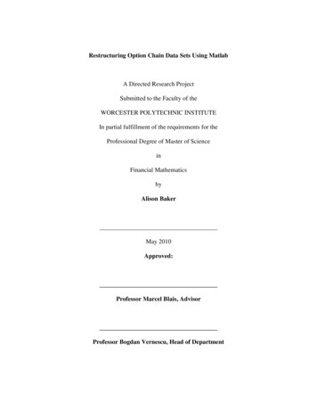
Crossover Design with MATLABAudio and Speaker-buildingMarch 24, 2007The last step is to combine the results of the circuits connected to the woofer and the tweeter. The tweeteris connected with reverse polarity (180 degree phase shift) in order to get the phase to line up correctlybetween the two drivers. To simulate that, call the function reverse on the treble network response. Thisfunction will draw a graph even if you don’t ask, because it’s a pretty important graph!result combine([lowsection reverse(highsection)]);That shows you how the sounds from the woofer and tweeter add together to give you full-range audiofrom about 80 Hz (the lower frequency limit of the woofer) to 20 KHz (the higher frequency limit of thetweeter, and also the limit of your hearing). The blue lines are the frequency response and impedance fromthe low frequency section; the red lines are from the high frequency section; and the black lines are thesummation of the two. Notice that at the crossover frequency of 2 KHz, the woofer and tweeter are playingequally strong (79 dB) and the sum of the two is about double the amplitude (6 dB higher, or 85 dB). That’sbecause the two drivers are in phase. If you run the simulation without reversing the phase on the tweeter,like this:result combine([lowsection highsection]);then you will get a big dip in the response at the crossover frequency, since the woofer and tweeter canceleach other out. It is sometimes hard to arrange the circuit components so that the phase is well-matched.That’s one of the things you get to play around with.If you change any of the circuit branches, call simulate and combine again to re-compute the results it doesn’t happen automatically.5
Crossover Design with MATLABOn to your own experiments!Audio and Speaker-buildingMarch 24, 2007Now that you have an idea about how this system works, it’s time to go on and simulate any circuitsyou can imagine. First, pick a driver from the list below and draw out a simple filter to connect to it. Makeup any reasonable values for the components and enter the circuits in using the load, branch, simulate,and combine functions. All of the information from these drivers came from the Parts Express web site,http://www.parts-express.com. You can find any drivers you want (navigate on the left to “Speakers”),view specifications, and download the FRD and ZMA data. There are more data files in the folder thanthere are drivers listed here - they’ll work just as s225rs270ModelAudax TM025F1Dayton PT2Dayton DC28Vifa XT25TGDayton DC50Audax AP100Z0Dayton RS-150Dayton RS-225Dayton RS-270Driver Description1” fabric dome tweeter5” long ribbon tweeter1” fabric dome tweeter1” dual concentric tweeter2” fabric dome midrange4” Kevlar/paper cone midrange6” aluminum cone woofer8” aluminum cone woofer10” aluminum cone wooferCost each 15 32 15 54 28 29 29 43 63Then you can get as ambitious as you want. My functions are prepared to handle as many differentcircuit sections as you can come up with (except maybe the plot commands). You can design a single driverspeaker with a filter to flatten its response, a 2-way with two woofers in parallel, or a 3-way with a separatewoofer, midrange, and tweeter.Suggestions for crossover designsWhen you try a crossover circuit, first draw it on a piece of paper. I would recommend making a nicesimple diagram like the one for the example on the next page. It’s much more helpful correcting it at thatstage instead of running the crossover simulation only to find that things have gone wacko.Starting Points for Crossover DesignThe idea of creating circuits from scratch might seem daunting. Maybe this willhelp.1. Don’t be afraid to try out any random capacitor value that pops into yourhead. You are not going to hurt anything by trying to put a 1,000 µF capacitorin parallel with a virtual tweeter. In fact, maybe you’ll learn something useful.2. Try taking a look at this web ml3. Enter in the “nominal” or rated impedance of each driver (usually 4 or 8 Ω)and the desired cutoff frequency.4. It will give you values for the capacitors and inductors in mH and µF, whichyou can enter as circuit branches.A 1st- or 2nd-order filter requires 1 branch per driver (plus an L-pad to reduce the tweeter level ifnecessary). A 3rd- or 4th-order filter needs 2 branches. As a general rule of thumb, lower cutoff frequenciesrequire bigger component values. A 2 KHz crossover in a 2-way might use capacitors around 5-15 µF andinductors around 1-2 mH, whereas a 500 Hz crossover in a 3-way might use capacitors around 20-60 µF andinductors around 4-10 mH. If you’re making a 3-way speaker, try to create two different crossover points:one between 100-500 Hz between the woofer and midrange, and one between 2-5 KHz between the midrange6
Crossover Design with MATLABAudio and Speaker-buildingMarch 24, 2007and tweeter. This means the midrange will have both lowpass and highpass filters attached to it (that’scalled a bandpass).Here are a few ideas, pick any one and give it a shot! Think about what each of these speakers wouldactually look like, how much it would cost, and what you would want it to sound like. Draw your imaginativevision of what the speaker would look like on a piece of paper, or search the internet for similar designs. Tryto come up with at least one crossover design completely from scratch. If you’re able to end up with a goodlooking frequency response, or you’ve got an interesting circuit. print out the results! I would love to seethem.And, keep our class project in the back of your head. What kind of speaker do you want to build? Doyou want to focus on this crossover design stuff or on something else, such as making a good subwoofer?1. Dayton RS-150 midwoofer an
Crossover Design with MATLAB Audio and Speaker-building March 24, 2007 The last step is to combine the results of the circuits connected to the woofer and the tweeter. The tweeter is connected with reverse polarity (180 degree phase shift) in order to get the phase to line up correctly between the two drivers. To simulate that, call the function reverse on the treble network response. This .