Transcription
www.bre.co.uk/nscBRE National Solar CentreA Technical Guide toMultifunctional Solar Car Parks Building Research Establishment 2018. Copyright attribution to BRE.
2Authors: Chris Coonick, BRE National Solar Centre and David Gance,BREEditor: John Holden, BRE GlobalBRE National Solar Centre would like to thank the following people fortheir input in to the development of this guide:Matthew Travaskis (ecodrive), Anthony Price (Electricity StorageNetwork/ Swanbarton), Guy Morrison (FlexiSolar), Sarah Glover(FlexiSolar), and Parveen Begum (Solisco)This guide is supported by:Front cover image courtesy of FlexiSolar.BRE National Solar Centre provides expert advice on solar technologies,such as solar car parks, and many other solar related topics.See www.bre.co.uk/nsc for more information.The production of this publication has been funded by InnovateUK, the UK’s innovation agency driven to support the science andtechnology innovations that will grow the UK economy.Any third-party URLs are given for information and reference purposesonly and BRE Ltd. does not control or warrant the accuracy, relevance,availability, timeliness or completeness of the information contained onany third-party website. Inclusion of any third-party details or websiteis not intended to reflect their importance, nor is it intended to endorseany views expressed, products or services offered, nor the companiesor organisations in question. Any views expressed in this publicationare not necessarily those of BRE. BRE has made every effort to ensurethat the information and guidance in this publication were accuratewhen published, but can take no responsibility for the subsequent useof this information, nor for any errors or omissions it may contain. Inparticular any standards, regulations and other documents referencedin this publication may be updated and/or withdrawn. In this respectreaders are encouraged to ensure they refer to the relevant versions ofreferenced documents. To the extent permitted by law, BRE shall notbe liable for any loss, damage or expense incurred by reliance on theinformation or any statement contained herein.A Technical Guide to Multifunctional Solar Car Parks
A Technical Guide to Multifunctional Solar Car Parks3ContentsPreface 4Solar inverter selection 19Energy storage system configuration 194Battery inverter selection 19System functionality 4Back-up operation requirements 20Design options 5AC system 20System integration 5AC isolation and circuit protection 20Solar PV module technologies 6Cabling 20Frames 7System earthing and bonding 20Drainage 7Earthing provisions in off-grid operation 21Advertising 8Lightning and surge protection 21Lighting 8Metering 21Inverters - general 8Solar inverters 8Battery inverters 9Battery storage system Overview of multifunctional solar car parks Considerations for mechanical design 22Structure 2210Carport frame 22Batteries 10Loading 22Electric vehicle charging 10Foundations 23Surface carparks 23Multi-storey car parks 24Solar car park layout 25Project Consents 12Distribution network connection 12Planning permission 13Building control 13Underground / overhead services 25Health and safety 14Component layout 25System signage 14Protection from damage 25Considerations for end of life 14Environmental protection of equipment 25Accessibility 26System performance 15System location 15Communications coverage 16System losses 16Modelling 16Monitoring 16Remote control 16Considerations for electrical design 17DC system 17DC connectors 17DC isolation and circuit protection 17PV modules 18PV array configuration 18Component warranties/ guarantees Commissioning Operation and maintenance 272728
4A Technical Guide to Multifunctional Solar Car ParksPrefaceSolar car park systems include a number of key components that require considerable electrical and mechanical design and integration. Solar carparks range in size from a single carport arrangement for one parking space ( 2kW generation capacity) to large multi-bay car parks (multi-MWgeneration capacity) and can be ground or building mounted (e.g. on the top deck of a multi-storey car park).This guide focuses on commercial and industrial sized systems (typically 50kW) that are connected to the distribution network.This guide provides a brief overview of the technical requirements and considerations for the design and installation of multifunctional elements ina solar car park system, including battery storage and dedicated plug-in electric vehicle (EV) charge-points.Inductive EV charge-points, off-grid systems and other forms of energy storage are not within the scope of this document.All solar car park systems should be designed and installed by a competent person to current standards, complying with relevant regulations andlegislation as highlighted in this document.Overview of multifunctional solar car parksIn this document a solar carport means a shelter for one or more cars that incorporates solar photovoltaic (PV) modules. A solar car park means aparking facility consisting of multiple solar carports.System functionalityMultifunctional solar car parks can provide a flexible energy system designed to fulfil a number of functions. Function requirements are site specificand take into account; onsite electrical loads (i.e. lighting, EV charging etc.) and storage capacity, solar generation capacity (size and performanceof solar array installed) and local distribution network conditions (i.e. limited or curtailed connection). Common system functions are detailed inTable 1.Table 1 Common functions of a multifunctional solar car park systemFunctionConsiderationGeneration of low carbon renewable energyGenerated electricity can be either consumed on site by any connected buildings, EV charge-points or otherloads, or can be sold to a nearby energy consumer under a power purchase agreement (PPA) via a private wire.Time-shifting for onsite consumptionThe inclusion of energy storage may help to increase self-consumption of solar generated energy by storingsurplus electricity for use when onsite energy consumption exceeds solar generation levels.Export limitingFor systems that have a restricted distribution network connection, energy storage can be utilised to store surpluselectricity for export when there is capacity to do so.Peak loppingThe inclusion of energy storage can provide additional supply capacity in times when onsite electricityconsumption exceeds the agreed supply capacity for short periods of time.ArbitrageFor sites with a time of use (ToU) tariff, the inclusion of energy storage can allow for electricity to be stored forexport when electricity prices are more favourable.Back-up/ energy securityFor systems in areas susceptible to power cuts there may be a requirement for the system to operate in ‘islandmode’ for short periods of time. Typically, an energy storage reserve will be sized to be able to provide criticalloads (such as for emergency lighting) for a specified period of time.EV chargingCombining solar car parks with EV charging is an opportunity to store renewable electricity in the EV’s batteriesduring daytime parking. This energy can then be utilized in the evening peak hours with vehicle-to-grid (V2G)technology. Power requirements will vary depending on the number of EV charge-points and the chargingregimes employed. Frequent recharges may reduce distribution network connection costs for the solar car park.Energy storage may also assist with increasing the percentage of electricity consumed in EV charging.Ancillary servicesThe inclusion of energy storage can also bring additional benefits through the provision of ancillary services to thetransmission system operator and local services to the distribution system.
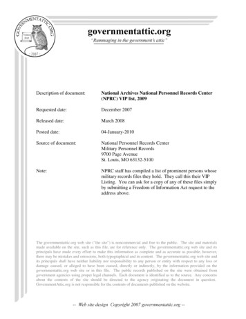
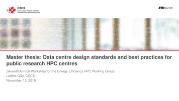
A Technical Guide to Multifunctional Solar Car Parks5Design optionsThere are a number of key components that make up a multifunctional solar car park. Selection of these components may be dictated by anoverall ‘solar carport’ product offering or can be defined by the client for aesthetic or practical reasons. Figure 1 details the most common designoptions available.FoundationsFigure 1 Common multifunctional solar carport design rel ArchBeamScrew PilesConcrete PilesConcrete PadsBallastBolted to StructureBallastSurfaceMultistoreyPV MountingPV ModuleInverterEnergy StorageEV ChargerPortal ramedStringCentralised BatterySlowLaminated GlassMicroDistributed BatteriesFastRapidThis guide provides information on the technical considerations for each component.System integrationIt is critical that a multifunctional solar carport is specified with due consideration to the onsite energy demands (now and in the future) and localdistribution network. Typically, it is more difficult and costly to retrofit additional components or provide additional functionality at a later date.It is important to have a clear understanding of what functions the multifunctional solar car park is required to provide, the order in which thosefunctions take priority and what other systems it may need to be integrated with (e.g. onsite energy management systems, Active NetworkManagement systems, etc.).This guide highlights areas where system integration needs to be considered.Key components may be integrated on either the DC or AC side of the solar carport system. Some typical system configurations are shown inFigure 2.
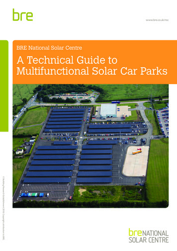
6A Technical Guide to Multifunctional Solar Car ParksFigure 2 Relationship between key components of an integrated multifunctional solar car park systemFigure 2 Relationship between key components of an integrated multifunctional solar car park system– laminated glass - two sheets of toughened glass sandwiching alayer of crystalline PV cellsSolar PV modules are constructeda numberof solar cellsfrom a number of solar cells composed of one or more materials.Solar PVfrommodulesare constructedcomposed of one or more PVmaterials.PVconnectedmodules connectedseries to as– asemi-flexiblemodulesin series areinreferredPV string. and flexible modules – PV cells applied to plastic, metal,are referred to as a PV string.or other substrates.There are many different makes and suppliers of PV modules. The vast majority of roof and groundThere are many different makes and suppliers of PV modules. Thetechnologiessiliconare beingdevelopedand manufacturingmounted PV installationsuse polycrystallineandNewmonocrystallinePV modulesmountedintovast majority of roof and ground-mountedPV adingto improved PV modulealuminiumframes.Due to theirlow costpolycrystalline and monocrystallinesiliconPV modulesmountedintoand availability, these are often used in solar carports.efficiencies and performance. The choice of technology needs carefulaluminium frames. Due to theirlow costavailability,these ofaresolar carports are more demanding than that of roof orHowever,the anddesignrequirementsconsideration. Certain technologies will be more appropriate for specificoften used in solar carports.ground-mountedHowever, the designrequirementssolarPV systemsand canofleadto thesystemuse of otherPVormoduleformatsas:functionality.designsto achievethe suchdesiredcarports are more demanding than that of roof or ground-mounted PVsystems and can lead to the useother PV moduleformatssuch as: of theA glazing offrameless– which usethe strengthand PVto PVprovidecomparisonofmountingthe more systemcommonmodule technologies is givenin Table 2.structuralintegrity,– frameless – which use the strength of the glazing and PV mounting laminated glass - two sheets of toughened glass sandwiching a layer of crystalline PV cells,system to provide structural integrity semi-flexible and flexible modules – PV cells applied to plastic, metal, or other substrates.Solar PV module technologiesSolar PV module technologiesTable 2 Comparison of commonPV moduletechnologiesNew technologiesare beingdeveloped and manufacturing processes are continually maturing,leading to improved PV module efficiencies and performance. The choice of technology needscareful consideration. Certain technologies will be more appropriate for specific system designs orCrystallinesilicon (c-Si)Thin Filmto achieve the desiredfunctionality.A comparison of the more common PV module technologies is givenAmorphousin Table 2. silicon (a-Si)Types of technologyTypical efficienciesTypical power outputTypical module sizeMonocrystalline silicon (mono-Si)Poly-crystalline silicon (multi-Si)Table 2 Comparison of common PV module technologies13% - 20%Crystalline silicon (c-Si)Types ofMonocrystallinesilicon (mono-Si)250W - 300W (60cells)technology300W – 400W (72cells)Poly-crystallinesilicon (multi-Si)1.6m2 – 2.0m2Some thin-film modules have a characteristic unique to the technology,referred to as a ‘soaking-in period’. This refers to a period of time whenthe thin-film module exhibits an increased voltage and current output(above their product specification), following their initial exposure tosunlight. It is important to ensure that the components specified foruse with such modules is capable of accommodating these electricalcharacteristics.Certain types of PV modules can be prone to potential induceddegradation (PID), a voltage potential between the PV module andCadmium telluride (CdTe)Copper indium gallium selenide (CIGS)Thin Film6% - 17%Amorphous silicon (a-Si)110W – 445WCadmium telluride (CdTe)1.1m2 – 2.2m2Copper indium gallium selenide(CIGS)the ground that can reduce PV module performance. The effectsof PID can worsen in PV systems that experience high levels ofhumidity, temperature and soiling. Some module manufacturers mayrecommend specific earthing arrangements for the DC system toreduce or reverse the effects of PID.The PV module casing and pre-fitted connector cables should bedouble insulated (safety class II) as recommended by BS 7671 forany system where the stri
2 echnical Guide to ultifunctional Solar Car Parks Authors: Chris Coonick, BRE National Solar Centre and David Gance, BRE Editor: John Holden, BRE Global BRE National Solar Centre would like to thank the following people for their input in to the development of this guide: