Transcription
Technical PaperNumber 102Crossover Networksfrom A to Linkwit-RileybyRichard ChinnAll Rights Reserved. Copyright 1986.Rick Chinn is a working sound engineer who has been involved in all facets ofrecording, sound reinforcement and acoustical design for the past fifteen years.He has written articles for Modern Recording and Music, Music and SoundOutput and A/V Video and has worked for TAPCO and Kaye-Smith studios. 22410 70th Avenue West, Mountlake Terrace, WA 98043 (425) 775-8461Price 1.00
Crossover Networks form A to Linkwitz-RileyCrossover networks have been with us for quite a while.1 Considering how long they’ve beenaround, you’d think that we had them figured out by now. As you will see, this is hardly the case.In recent years, new research has brought additional facts to light. With each new bit of knowledge, another piece of the puzzle falls into place.What Is A Crossover?It is hard to make a loudspeaker that is capable of handling the entire audio spectrum. It is moredifficult to make one that does this well. It is much easier to make a loudspeaker capable of onlyhandling a limited portion of the audio spectrum.The earliest multi-way systems used only two loudspeakers (drivers). They were called two-waysystems because the audio spectrum was split into two-parts and fed to two drivers. You can stillfind large two-way systems in use today in movie theatres and in sound reinforcement. Two-waysystems are by no means the be-all and end-all of high-fidelity. You can find commercially madespeaker systems that range from one-way to five-way and beyond. More is not necessarily better.It’s interesting to note that in most recording studios, the control-room monitor speakers are stilltwo- or three-way designs, based on the old theatre systems of the 1930s. The multiple-driverapproach is the basis of contemporary loudspeaker system design.The crossover network’s (okay, from now on, we’re just going to call it the crossover.) role in all ofthis is to divide the incoming audio signal into sub-ranges of the entire audio spectrum. Typically,there is one crossover output for each loudspeaker in a multi-way design. Since the limiting factoris the capability of the drivers used to make up the system, the drivers dictate the choice of crossover frequency(s).For example, sending excessive low-frequency (bass) energy to a tweeter (high-frequency speaker),is usually an easy way to send it to its grave. The tweeter’s cone is not capable of moving farenough to reproduce the lower frequencies. If the tweeter’s cone isn’t damaged by the excessivemovement, then the voice coil may burn up because of the extra energy content of the lowerfrequencies.There’s more to the choice of crossover frequency than just the capabilities of the drivers involved,but for now, this will suffice.1. J. K. Hilliard, “Loudspeaker Dividing Networks,” Electronics, January, 1941.1
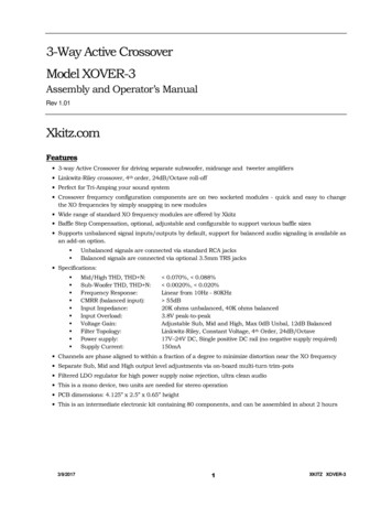
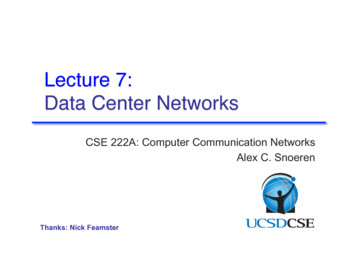
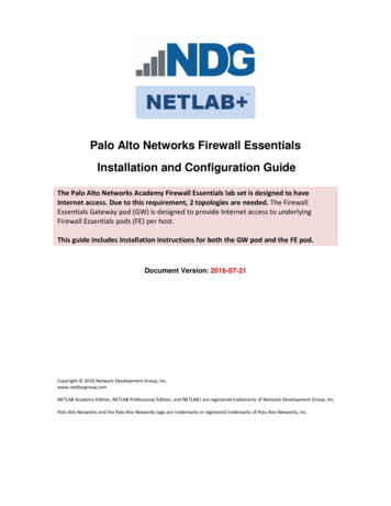
How Do They Work?A crossover is nothing more than a pair (more if we aren’t talking about a two-way system) ofelectrical filters. These filters are known as highpass and lowpass filters. Systems other than twoway use bandpass filters for the intermediate ranges of the audio spectrum.Figure 1. A 1000 Hz highpass filterA highpass filter’s output is shown graphically in Figure 1. As you can see, the output is zero atDC (0 Hz) and rises progressively at higher frequencies. The cutoff frequency of the filter is thefrequency where the output is 3 dB down from the output in the level region of the graph. Thecutoff frequency for our example is 1000 Hz. As you can see, the output progressively decreasesas frequency decreases. If you were to listen to this signal, it would sound like a loud, tinny,transistor radio. A common misconception is the belief that there is no output below the cutofffrequency of the filter. A filter of this type is known in engineering circles as a “brick wall filter.”A brick wall filter is a mathematical impossibility to achieve. Figure 2 shows the frequencyresponse of such a filter.Figure 2. A brick wall filter2
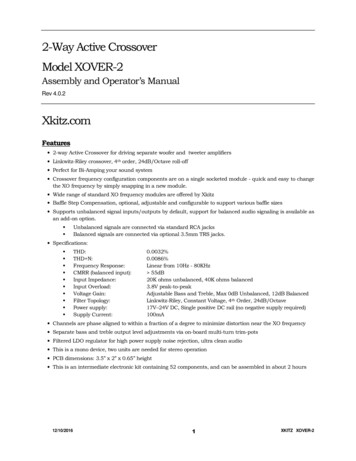
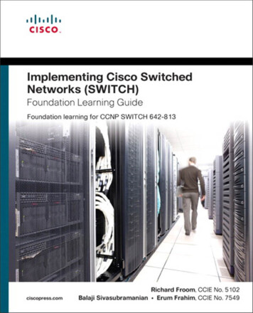
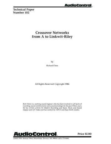
How Do They WorkFigure 3. A 2000 Hz lowpass filterFigure 3 shows a 1000 Hz lowpass filter. It’s output is the inverse of the filter shown in Figure 1.If these two filters were used as a crossover network, what the crossover frequency would be? Ifyou said 1000 Hz, you’re right. The crossover frequency is the frequency where the two curvescross each other. Figure 4 shows the two curves overlaid on each other.Figure 4. A 1000 Hz crossover3
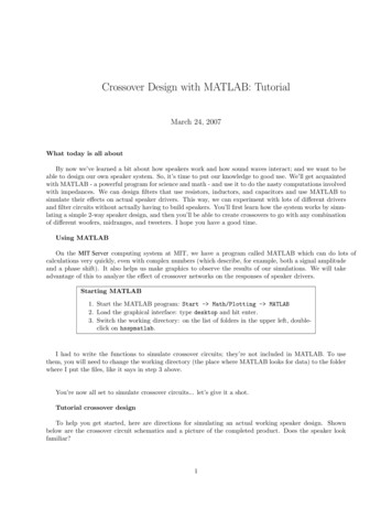
How Do They WorkA bandpass filter is simply a lowpass filter followed by a highpass filter. The cutoff frequenciesaren’t necessarily the same, in fact they’re usually quite different (like 500 Hz and 5000 Hz).Figure 5 shows a three-way crossover using the above frequencies. Figure 6 shows how thesefilters are connected to the loudspeakers.Figure 5. A three-way crossoverFigure 6. Connecting the crossover into the system4
Types of CrossoversTheoretically, the acoustical output of the crossover/speaker system should be the same as theoutput of a single perfect loudspeaker. This is not as simple as it sounds.There are many different types of crossovers. Now in this context, the word type refers to something distinctly different than just the number of audio sub-ranges that the unit is capable ofproviding. What we’re referring to here is the slope and roll off characteristic of each crossoveroutput. This is equally applicable to a two-way as well as a five-way crossover design.Crossover slopeThe slope of a crossover (actually, the slope of the output of the filters that make up the crossover)is the rate of change of the output voltage for a given change in the input frequency, with the inputvoltage held constant. Typically the slope is stated in terms of dB/octave. For a number of mathematical reasons, the slope of a filter is almost always a multiple of 6 dB/octave. Let’s put itanother way. It’s much more difficult to design for a slope that isn’t a multiple of 6 dB/octave.Sometimes, the slope of the crossover is stated by describing it as “nth” order. In this case, the“order” is the order of the equation that describes the filter’s characteristics. You can convert thisto the slope by multiplying the order by 6 dB/octave. Thus, a second-order crossover has a slope of12 dB/octave.The effect of larger (steeper) slope characteristics is to make the individual filter characteristic lookmore and more like a brick wall filter. In more practical terms, it means less output in the regionbeyond the crossover frequency.Crossover cutoff characteristicIn addition to slope, another attribute is the cutoff characteristic. Simply stated, this is the shape ofthe input/output curve as it makes the transition from the passband (level portion) to the stopband(where the slope is measured).Although there are many different cutoff characteristics, there are enough similarities to group thedifferent types into families based on the mathematical formula that defines the filter. This formulais known as the filter’s transfer function. For one reason or another, mankind has chosen to namethese different families after the mathematicians who identified them. The most common filtersused for crossover filters have Butterworth, Tchebychev, or Bessel transfer functions. Here is asynopsis of each of them: Butterworth filters are maximally flat in their passband. The have the flattest passband responseof the three types mentioned. Tchebychev filters roll off faster than Butterworth filters of the same slope. They do this at theexpense of the flatness of the passband response. For this reason, they are not terribly popularas crossover filters. Bessel filters do not roll off as fast as either the Butterworth or Tchebychev filters. For mostloudspeaker crossovers, fourth-order is a practical minimum if you want to use a Bessel filter.On the other hand, this filter has the best phase performance of the three.5
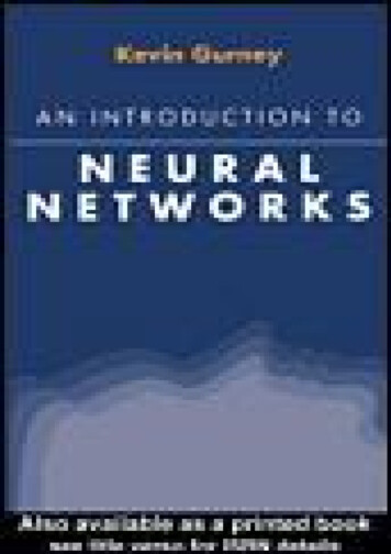
An Overview of Crossover NetworksNow that you have had a glimpse of the world of crossovers, it’s time to explore a few of thevarious types, and their advantages and disadvantages.First-Order NetworksThe first-order network produces a roll off characteristic of 6 dB/octave. It is inherently phasecoherent, and the two crossover outputs combine perfectly. A typical circuit and some curves areshown in Figure 7.Figure 7. A first order crossover networkOn the negative side, the first-order network’s roll off is not very sharp, and the drivers must becapable of delivering (as well as handling) significant output below the crossover point. Furthermore, the large amount of overlap requires the drivers to match fairly well, both from a frequencyresponse standpoint as well as from a phase shift standpoint. This is a tall order.Second-order Butterworth NetworksThe second-order Butterworth crossover has been the mainstay of theatre-style speakers for over 5decades. The roll off characteristic is fairly sharp (12 dB/octave), and doesn’t make ridiculousdemands on the drivers. Figure 8 shows a typical second-order Butterworth crossover.Figure 8. A second-order Butterworth crossover6
An Overview fo Crossover NetworksOn the other hand, at the crossover point, the two outputs are 180 degrees out of phase with eachother. A common cure for this is to reverse the phase of the high-frequency driver by interchangingthe two connecting wires. (Note that the net result is to place the high-frequency driver in-phasewith the low-frequency driver.) Electrically speaking, if you sum the two outputs out-of-phase, youget an infinite null. Fortunately, loudspeakers don’t sum acoustically that well, so the differencesare either a small peak, or a small dip at the crossover frequency. Nevertheless, the second-orderButterworth crossover has fallen into disfavor.Third-order Butterworth NetworksThe third-order Butterworth crossover combines a fast roll off characteristic (18 dB/octave) withgood phase characteristics. The two crossover outputs sum together well in either polarity, and theresultant phase response is a gradually changing shift over the audio range. Figure 9 shows atypical third-order Butterworth crossover.Figure 9. A third-order Butterworth crossoverOn the negative side, the third-order network can not be corrected using time delay for the casewhere the loudspeakers do not radiate from the same vertical plane (which is the usual case!). Thisnotion is discussed further a bit later in this paper.Butterworth and Linkwitz-Riley fourth-order crossoversThe fourth-order Butterworth crossover suffers from the same problem that the second-orderButterworth crossover suffers from.the outputs are 180 degrees out-of-phase at the crossoverfrequency. True, the 24 dB/octave slope greatly minimizes the interaction between the drivers in thecrossover region, but the phase problem overshadows this. Although the previous figures haveshown passive networks, the complexity of a fourth-order network make it pretty economicallyunfeasible for a passive, high-level (speaker level) crossover. Figure 10 shows a typical activefourth-order Butterworth crossover.7
An Overview fo Crossover NetworksFigure 10. A fourth-order Butterworth crossoverA special case of the fourth-order Butterworth crossover is the fourth-order Linkwitz-Rileycrossover. The slope is still 24 dB/octave, like the fourth-order Butterworth crossover, but theindividual filter outputs are 6 dB down at the crossover point. This is what makes this crossoverdifferent from all the others. The usual implementation of this crossover is a simple series connection of two second-order Butterworth filters (two for the high-pass channel, and two more for thelow-pass channel). Figure 11 shows a Linkwitz-Riley crossover.Figure 11. A Linkwitz-Riley crossoverSimple in concept, elegant in performance, the Linkwitz-Riley crossover achieves what all theothers set out to do: The outputs will sum with flat frequency response. The outputs are in-phase at the crossover frequency. The phase relationship of the output allows time correction for drivers that are not in the sameacoustic plane.8
The Effects of Phase ShiftAn unavoidable consequence of highpass, lowpass, or bandpass filter design is phase shift. It’sway beyond the scope of this discussion to do anything but touch upon the subject. In a nutshell,any network that affects the amplitude of a signal will also affect its phase in a predictable manner.What is phase anyway? In a nutshell it is the time relationship of two signals. You’ve probablyencountered a very basic phasing problem in connecting two loudspeakers in a stereo system. If thetwo systems aren’t in-phase, the bass output partially cancels and the result is a thin soundingsystem. Reversing the wires to one of the speakers corrects the problem by inverting the phase ofthe signal going to that speaker. This is an example of a 180 degree phase shift. In crossovers,we’re dealing with phase shifts that may start at 0 degrees, and gradually change to well over 360degrees.How does phase shift affect a crossover? Good question, because if we ignored the phase shift, therest would be easy. The phase shift caused by the crossover filters affects two things: The ability of the crossover/loudspeaker system to reproduce transient-type (pulse) waveforms. The flatness of the combined acoustical output of the two (or more) drivers. The radiation angle of the loudspeaker’s output. Different crossovers cause differences in theangle at which the combined output of the various drivers reaches a maximum. Figure 12illustrates the concept of radiation angle. The change in radiation angle is also frequencysensitive. At frequencies near the crossover point, both drivers contribute to the total acousticoutput. The change in radiation angle occurs because of the frequency sensitive phase shift thatoccurs in the crossover region. At frequencies far removed from crossover, the radiation patternsshifts to that of the individual drivers.Fi
output. This is equally applicable to a two-way as well as a five-way crossover design. Crossover slope The slope of a crossover (actually, the slope of the output of the filters that make up the crossover) is the rate of change of the output voltage for a given change in the input frequency, with the input voltage held constant. Typically the slope is stated in terms of dB/octave. For a number of math-File Size: 259KBPage Count: 12