Transcription
DELAWARE STATE-WIDE INFORMATIONTECHNOLOGY AND ARCHITECTURE STANDARDSStandard ID:Title:Domain:Discipline:Revision Date:Revision no.:Original date:NE-Cabling-002Structured Cabling System Standards and Specifications forState-Managed FacilitiesNetwork and StorageCabling8/2/201357/21/2008A. Authority: Title 29, Chapter 90C provides broad statutory authority to the Department ofTechnology and Information to implement statewide and interagency technology solutions, policy,standards and guidelines for the State of Delaware's technology infrastructure. "Technology"means computing and telecommunications systems, their supporting infrastructure andinterconnectivity used to acquire, transport, process, analyze, store and disseminate informationor data electronically. The term "technology" includes systems and equipment associated with egovernment and Internet initiatives.B. Applicability: Applies to all State of Delaware communications and computing resources. DTI isan Executive Branch Agency and has no authority over the customers in Legislative and JudicialBranches, as well as School Districts, and other Federal and Local Government entities that usethese resources. However, all users, including these entities, must agree to abide by all policies,standards promulgated by DTI as a condition of funding, access and continued use of theseresources.C. Purpose: Cable configuration and installation is critical to providing connectivity in State buildings.This standard provides guidance for the design and installation of cabling. This standard providesguidance and requirements for data, voice, and CATV structured cabling systems and supportinfrastructure in all State owned and leased facilities and buildings.These standards are adopted by the Department of Technology and Information (DTI), through the Technology and Architecture StandardsCommittee (TASC), and are applicable to all Information Technology use throughout the State of Delaware. Any questions or commentsshould be directed to dti tasc@state.de.us.Page 1 of 708/15/201411:54:59 AMCablingandWiringStandard-State.doc
DELAWARE STATE-WIDE INFORMATIONTECHNOLOGY AND ARCHITECTURE STANDARDSTable of ContentsPART 1 Scope. 3PART 2 Process . 3PART 3 Executive Summary . 3PART 4 Objective . 4PART 5 Credits . 5PART 6 Introduction. 5PART 7 Procedures. 8PART 8 Horizontal Distribution System . 9PART 9 Communications/Data Rooms/Closets (General) . 11PART 10 MDF & IDF Product Specifications . 25PART 11 Information Outlets . 37PART 12 Cable Routing Systems . 42PART 13 Cabling-General . 43PART 14 Horizontal CABLING - Category 6 UTP Data . 44PART 15 Vertical Distribution Systems . 47PART 16 Campus Cabling. 50PART 17 Patch Cables. 52PART 18 Fire Stop - Penetration Sealant . 55PART 19 Testing . 56PART 20 Appendix A – Communications Planning Checklist . 61PART 21 Appendix B - Cable Installation Checklist . 62PART 22 Appendix C - Quality Assurance . 63PART 23 Appendix D - Codes, Regulations and Standards . 63PART 24 Appendix E - Warranty. 63PART 25 Appendix F - Bid/Quote Response Format . 64PART 26 Appendix G - Outside - DELDOT Specific Requirements - TrafficConstruction . .65PART 27 Appendix H - Certified Contractor List . 70These standards are adopted by the Department of Technology and Information (DTI), through the Technology and Architecture StandardsCommittee (TASC), and are applicable to all Information Technology use throughout the State of Delaware. Any questions or commentsshould be directed to dti tasc@state.de.us.Page 2 of 708/15/201411:54:59 AMCablingandWiringStandard-State.doc
DELAWARE STATE-WIDE INFORMATIONTECHNOLOGY AND ARCHITECTURE STANDARDSPART 1SCOPEA.Areas Covered: This standard covers the best practices and installation requirements for Voice,Data, CATV cabling and support structures including conduits and raceways, Voice and Datarooms and closets.B.Environments: This standard applies to all State owned and leased building and office spaces. Itis concerned with all Data, Voice and CATV cabling projects, whether they are for newconstruction or revisions additions and upgrades to existing systems.PART 2PROCESSA.Adoption: These standards have been adopted by the Department of Technology andInformation (DTI) through the Technology and Architecture Standards Committee (TASC) and areapplicable to all Information Technology use throughout the State of Delaware.B.Revision: Technology is constantly evolving; therefore, the standards will need to be regularlyreviewed. It is the intent of the TASC to review each standard annually. The TASC is open tosuggestions and comments from knowledgeable individuals within the State, although we ask thatthey be channeled through your Information Resource Manager (IRM).C.Contractors: Contractors or other third parties are required to comply with these standards whenproposing technology solutions to DTI or other State entities. Failure to do so could result inrejection by the Delaware Technology Investment Council. For further guidance, or to seekreview of a component that is not rated below, contact the TASC at dti tasc@state.de.us.D.Implementation responsibility: DTI and/or the organization’s technical staff will implementthese best practices during the course of normal business activities, including business casereview, architectural review, project execution and the design, development, or support ofsystems.E.Enforcement: DTI will enforce these best practices during the course of normal businessactivities, including business case and architectural review of proposed projects and during thedesign, development, or support of systems. These best practices may also be enforced byothers during the course of their normal business activities, including audits and design reviews.F.Contact us: Any questions or comments should be directed to dti tasc@state.de.us.PART 3EXECUTIVE SUMMARYBecause of ever-advancing Industry Standards and new Alliances between Cable and HardwareManufactures and Vendors, this document seeks to enhance and clarify the State of Delaware’s wiring andcabling standards and specifications for Structured Cabling Systems. Approved Contractors under State ofDelaware Contract # 05-441-TL are required to adhere to these specifications and standards.The structured cabling system will support Voice, Data, and imaging applications within State-owned and leased office facilities. This document describes the Structured Cabling System requirements to be met inthe proposals for Communications cabling by Vendors and Contractors. These requirements encompass allmaterials, design, engineering, installation, supervision, and training services for a Structured CablingSystem.These standards are adopted by the Department of Technology and Information (DTI), through the Technology and Architecture StandardsCommittee (TASC), and are applicable to all Information Technology use throughout the State of Delaware. Any questions or commentsshould be directed to dti tasc@state.de.us.Page 3 of 708/15/201411:54:59 AMCablingandWiringStandard-State.doc
DELAWARE STATE-WIDE INFORMATIONTECHNOLOGY AND ARCHITECTURE STANDARDSThe following are examples of the Structured Cabling Systems that can be bid for new construction andwhole building renovations, in which case all building structured cabling wiring is replaced. The choice of aStructured Cabling System is not limited to the Vendors or Manufactures listed below. The ChannelSolutions shall be bid when possible. If a Link solution is bid the State Contact, PM, or DTI (Department ofTechnology and Information) must authorize the installation.In new construction projects, the default cabling infrastructure shall be Category 6 unless specifiedotherwise. Where building renovations and additions do not require the removal of the existing structuredcabling system, the existing cabling in conjunction with new cabling should maintain the system warranties. Ifthe existing structured cabling system is not Category 5e or better, it must be upgraded to CAT5e or better. Hubbell Premise WiringOrtronicsPanduitSystimaxNote: When a Structured Cabling Solution is chosen, STATE/DTI requires that the enhanced version beused to provide maximum performance.A.Terms and Conditions of Bids/quotes1. An approved Contractors bid submittal should be based on the materials, systems, equipment,and Standards described in this document and in the bid response format of the attachedexample. Refer to Appendix G. All bids must be submitted in accordance with the specificationsand information contained herein, as well as with any addenda, if required.2. The bid package shall be accompanied by a presale warranty commitment, binding theInstallation Contractor and Manufacturer to the customer-selected extended warranty packageas described in State Contract # 05-441-TL page 21 section 3) paragraph b).3. At any point in time, should you require clarification or have any questions pertaining to thecontent of this document, please call The State of Delaware Department of Technology andInformation (DTI). 302-739-9500PART 4OBJECTIVEThis document has been developed as a source of information to assist in the design, implementation andmaintenance of Voice, Data and Broad Band communications systems. It contains standards andspecifications which guide users through structured cabling system design, planning, and installation.To maximize the usefulness of this document, access to the various TIA/EIA (Telecommunications IndustryAssociation/Electronic Industries Alliance), IEEE (Institute of Electrical and Electronics Engineers), BISCI,(Building Industry Consulting Service International), NEC (National Electrical Code), NFPA (National FireProtection Association) Communications Standards, and implementation and installation Manuals for furtherreference is required. This document assumes that users have communications knowledge and training in allaspects of design, implementation, installation, and testing of a Voice/Data communications system.This document does not address safety issues associated with use. It is the individual’s responsibility to useestablished and appropriate safety and health practices and to determine the applicability of all regulations.These standards are adopted by the Department of Technology and Information (DTI), through the Technology and Architecture StandardsCommittee (TASC), and are applicable to all Information Technology use throughout the State of Delaware. Any questions or commentsshould be directed to dti tasc@state.de.us.Page 4 of 708/15/201411:54:59 AMCablingandWiringStandard-State.doc
DELAWARE STATE-WIDE INFORMATIONTECHNOLOGY AND ARCHITECTURE STANDARDSPART 5CREDITSCommunications Cabling ConstructionDeveloped by:State of Delaware Department of Technology & Information801 Silver Lake Blvd. Dover, DE19904The content of this document is drawn from experience, as well as other documentsand manuals, including the following: NEC 2011 Code bookNFPA-70 PublicationsTIA/EIA Communications Building Wiring StandardsIEEE Publications & StandardsBICSI Communications Distribution Design and Installation PublicationsMOTOROLA R56 Standards and Guideline for CommunicationsVarious Manufactures Publications and RequirementsPART 6INTRODUCTIONAny Structured Universal Cabling System installed for the Agencies of the State of Delaware is designed tomeet known and anticipated technology needs within the State. An advanced building cabling systemprovides for more than communication services; it provides an infrastructure for an institution’s entirecommunications network. Instead of being a basic utility, it is as important as the high-tech systems thattransmit signals over it and is an integral component of the State’s overall information network.These designs provide a universal and flexible cabling system for workstations, conference rooms, andlaboratories. Today’s cabling system must be multi- functional and provide service for telephones,computers, fax machines, LANs, WANs, broad band fiber optic and coaxial systems (CATV, SATV, CCTV.),Data Centers, computer-aided design workstations, Audio Video systems (AV), and other technologies. Fora cabling system to be capable of meeting today’s technology and institutional demands, it must have highbandwidth capacity and transmission speed while being extremely flexible.This wiring architecture incorporates the applicable ANSI/EIA/TIA standards, BICSI guidelines and the latesttechnologies. This cabling distribution plan can integrate all types of systems from a variety of vendors. Thedesign uses a subsystem approach, which allows for changes in the system without affecting other parts ofthe system. The Main Distribution Frame (MDF) and Intermediate Distribution Frame (IDF) Room equipmentracks are designed to allow for growth, and the cable routing is accomplished through the provision of cabletrays, conduits, sleeves, raceways, and cable hangers where required. Ease of administration andrecordkeeping for moves and changes is readily apparent, as is the flexibility that a structured cablingsystem provides.The wiring medium for the Communications Cable Network consists of Category 5e or Category 6 – 6a24AWG Unshielded Twisted Pair (UTP) for station cabling and multi pair twisted copper for backbone cablingto support low-speed voice or Data, Category 6 or 6a for high speed LAN technologies, and 50/125 micronmulti-mode fiber optic cable and 50/125 micron multi-mode for even higher bandwidth requirements. Theunshielded twisted pair (UTP) Category 5e and Category 6 or 6a LAN cables can support Data transmissionThese standards are adopted by the Department of Technology and Information (DTI), through the Technology and Architecture StandardsCommittee (TASC), and are applicable to all Information Technology use throughout the State of Delaware. Any questions or commentsshould be directed to dti tasc@state.de.us.Page 5 of 708/15/201411:54:59 AMCablingandWiringStandard-State.doc
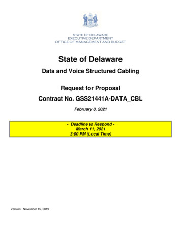
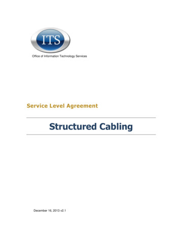
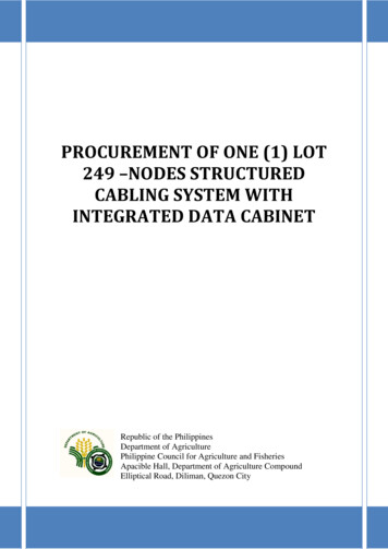
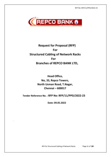
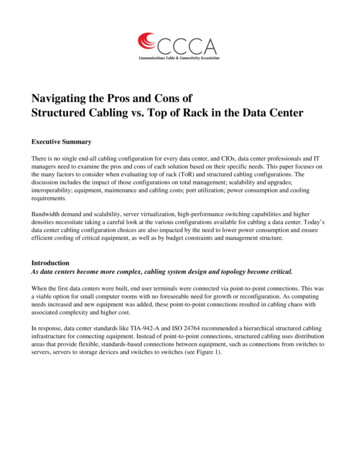
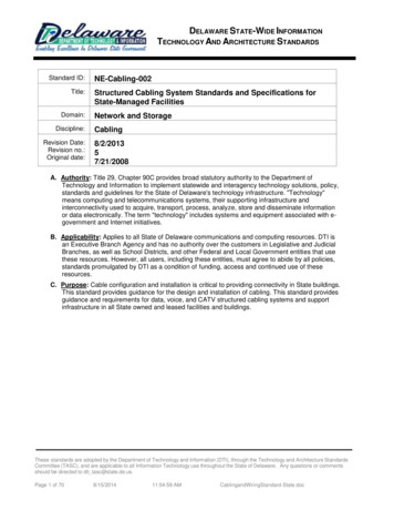
DELAWARE STATE-WIDE INFORMATIONTECHNOLOGY AND ARCHITECTURE STANDARDSrates of 100, 250 and 500 Mb/Sec respectively according to EIA/TIA Standards and manufacturers’specifications. These leading edge components, combined with the open wiring architecture, provide thetechnology, flexibility, and modularity that allow the system to grow and change to meet changing needs.The central distribution location of the system is the Fiber Optic, coaxial and Copper Main Distribution Frame(MDF) located within the centrally located MDF/IDF Room of each building. Various fiber optic, coaxial andcopper riser cables terminate on the MDF and extend to the Communications Rooms/Closets (IDFs) locatedthroughout the buildings. Each building typically has one MDF/IDF Room and a varying number of IDFrooms/closets dictated by the horizontal station cabling limitation of 100 meters for high performance cable.The distance from the information outlet to the termination within the IDF is limited to 90 meters (thepermanent link). The IDF room/closet houses the Intermediate Distribution Frame (IDF), Copper and FiberOptic IDF Patch Panels, Local Area Network (LAN) equipment, and other electronics. Both the riser cablesand the horizontal station cables feeding the floor’s workstations information outlets terminate in the IDF onData patch panels, Voice 110 hardware, and Fiber Optic Patch Panels. These termination points act as thecross-connect point between the MDF and the floor that is being served. Large floors are divided into zones,via an imaginary line, with each zone being served by its respective IDF room/closet. (See figure 1)Each work area and workstation is served by an information outlet, which provides the jacks for plugging intelephones, computers, broad band coaxial systems, fax machines, modems, and other devices at thedesktop. The information outlets are served by varying sets of cables consisting of fiber optic and coppertechnologies, which originate in the IDF Room. IDF outlets are typically displayed as varying types oftriangles (shaded, half-shaded, etc.) on blueprints. (See figure 2)A subsystem architectural approach, using the latest technologies, provides a comfortable level of assurancethat the system will support new applications and industry standards as they emerge.These standards are adopted by the Department of Technology and Information (DTI), through the Technology and Architecture StandardsCommittee (TASC), and are applicable to all Information Technology use throughout the State of Delaware. Any questions or commentsshould be directed to dti tasc@state.de.us.Page 6 of 708/15/201411:54:59 AMCablingandWiringStandard-State.doc
DELAWARE STATE-WIDE INFORMATIONTECHNOLOGY AND ARCHITECTURE STANDARDSFIGURE 1These standards are adopted by the Department of Technology and Information (DTI), through the Technology and Architecture StandardsCommittee (TASC), and are applicable to all Information Technology use throughout the State of Delaware. Any questions or commentsshould be directed to dti tasc@state.de.us.Page 7 of 708/15/201411:54:59 AMCablingandWiringStandard-State.doc
DELAWARE STATE-WIDE INFORMATIONTECHNOLOGY AND ARCHITECTURE STANDARDSFIGURE 2PART 7PROCEDURESDesigning a cable system for an institution involves various organizations and individuals and requires agreat deal of coordination. Once an institution is designated for wiring, AutoCAD drawings of the floor plansneed to be acquired. AutoCAD is a type of computer aided drafting (CAD) format. These files are plotted andconverted to blueprints that serve as the working drawings for site surveys and engineering purposes. Basedon interviews with the agency's staff and Technical Coordinator will draw triangles on the drawing displayingthe locations that information outlets are to be located. Also, tentative locations for the Communications/Datarooms/closets will be marked on the drawings. This information will be approved by the institution’s officialsand sent to the engineering team.The engineers will survey the building—floor plans for new construction—and evaluate the communicationsrooms/closets, plan cable routing, and review the information outlet locations. The necessary adjustmentswill be made during the site survey, and the engineer will leave the site with the proper approvals from theagency's management if there are major changes such as room relocations.The engineering team will then design the cable system for the building. The end product will be submitted tothe agency's Technical Coordinator for comment. If no adjustments are necessary, the blueprints are issuedto the contractor for construction.These standards are adopted by the Department of Technology and Information (DTI), through the Technology and Architecture StandardsCommittee (TASC), and are applicable to all Information Technology use throughout the State of Delaware. Any questions or commentsshould be directed to dti tasc@state.de.us.Page 8 of 708/15/201411:54:59 AMCablingandWiringStandard-State.doc
DELAWARE STATE-WIDE INFORMATIONTECHNOLOGY AND ARCHITECTURE STANDARDSPART 8HORIZONTAL DISTRIBUTION SYSTEMThe horizontal structured cable plant is the portion of the communications wiring system that extends fromthe information outlet to the Communications/Data room/closet.A.Horizontal Distribution System General1. The horizontal distribution system includes the: Information outlet at the workstation Cables connecting the workstation to the Communications/Data room/closet Intermediate routing and distribution systems2. The horizontal distribution system should be configured in a star topology. All communicationsoutlets within a work area should be connected to a single Communications/Data room/closet, asdefined by the zone concept.3. This infrastructure must serve all of the Communications requirements of the agency or owner.4. Communications applications served by the horizontal system can include: Voice (e.g., telephones)Data (e.g., terminal connectivity, modems, etc.)Local area networks (e.g. Ethernet)Audio & Video (e.g., CATV, video conferencing and security monitoring)Graphics & Imaging5. When designing a horizontal distribution system, include capacity to satisfy long- termrequirements as well as initial plans. Ensure that the distribution system has the flexibility toaccommodate necessary moves, additions, changes, and system growth.6. After construction, the horizontal distribution system is typically difficult to access. Therefore thetime, effort, coordination, and skills required for changes can be extremely costly. In addition,access to the horizontal distribution system frequently causes disruption to the user community.7. All Horizontal Workstation Communications and broad band coaxial system cabling will be "homerun" from the information outlet location to the termination point within the corresponding IDF orMDF/IDF room.8. Horizontal cable paths will be in a "streets and avenues" manner, typically following mainwalkways.9. Horizontal cables are to be fastened onto hangers five feet apart with all cables bundled with tiewraps, and are to have a small amount of slack visible.10. Cables must not rest on any structures or the hung ceiling. Cables are not to be fastened to ducts,pipes, conduits, or any other existing structures. Cable bundles should be secured to the slaboverhead to avoid any conflict with or EMI from flexible electrical conduits, transformers, motors,etc.11. Some cabling shall run to workstation and other outlets through cavities in the dry wall andopenings in sheet metal or wooden studs within the dry wall construction. The sheet metal studswill not have gaskets for this purpose, so it is the Contractor's responsibility to exercise extremecare in snaking cable through these areas, so as to avoid damage to the cable jacketing.These standards are adopted by the Department of Technology and Information (DTI), through the Technology and Architecture StandardsCommittee (TASC), and are applicable to all Information Technology use throughout the State of Delaware. Any questions or commentsshould be directed to dti tasc@state.de.us.Page 9 of 708/15/201411:54:59 AMCablingandWiringStandard-State.doc
DELAWARE STATE-WIDE INFORMATIONTECHNOLOGY AND ARCHITECTURE STANDARDS12. The building's horizontal wiring plan is to be installed on all floors from the information outlet to thetermination point within the associated IDF Room.13. Horizontal cable will be installed onto “J” hooks or equivalent in the ceiling or tops of walls nearceiling. Cables are to be fastened to “J” hooks or equivalent every 5 feet. The cable contractor is toprovide and furnish the “J” hooks.14. All station cable (horizontal) and tie cables that run from relay racks to the wall- mounted framesare to be plenum-rated.B.Horizontal Communications Cable Specification1.For each type of information outlet indicated on the attached drawings, the contractor shall furnishall of the following equipment, install it in the correct configuration, and test it.2.All cabling, outlets, and termination patch panels used for the Category 6 / ISO Class E datasystem may be provided by a single manufacturer and shall be certified as part of the 25 yearminimum warranty- Where the installer chooses to use one (1) manufacturer for cabling and adifferent manufacturer for the outlets and termination patch panels for the Category 6 / ISO ClassE data system, the two (2) manufacturers must prove to have compliant interconnecting hardwareand shall be certified as part of the 25 year minimum warranty.3.All Category 5e, 6, and 6a UTP & Fiber cabling is to be handled and terminated in accordance withthe Manufacturer’s Premises Communications Application and Installation Guide.4.In addition to the above manufacturer’s standards, all applicable EIA/TIA Category 5e and 6 andFiber Optic Cable standards are to be strictly adhered to.5.The fiber optic cable is to be terminated on both ends with an LC type connector.6.The contractor is to use Plenum cable for all station 4-pair copper, coaxial, and 2-strand fibercabling.7.Plan routes to ensure that the proposed route on the plans falls within the EIA/TIA distancelimitations (90 meters after termination) for horizontal cabling.8.Cables serving information outlets that cannot be routed down wall cavities will be enclosed inlatching surface-mount raceways, anchored (not with adhesives) to walls. Contractor will provideall raceway fittings to allow for level and plumb routes from ceiling to information outlet. Proper fillratios must be observed. Contractor may reference the manufacturer’s catalogs or specificationsfor correct fittings and fill ratios. Contractor must use all accessory fittings required in order to builda neat and functional installation. This same method will apply to routing horizontal cables toworkstation outlets where ceilings are not accessible.9.The RG-6U Plenum Cable and the RG11U Plenum Cable are to be terminated with F typeconnector or connectors. The RG6U Coaxial Station cabling will be terminated onto a rack or wallmounted “F” Connector Patch Panel located in the IDF Room.10. The IDF Room side of the Voice four-pair cables serving a standard outlet will be punched downon the corresponding IDF Room's wall-mounted frame on 110 Cat 5e field-terminated cross-These standards are adopted by the Department of Technology and Information (DTI), through the Technology and Architecture StandardsCommittee (TASC), and are applicable to all Information Technology use throughout the State of Delaware. Any questions or commentsshould be directed to dti tasc@state.de.us.Page 10 of 708/15/201411:54:59 AMCablingandWiringStandard-State.doc
DELAWARE STATE-WIDE INFORMATIONTECHNOLOGY AND ARCHITECTURE STANDARDSconnect terminal blocks.11. The IDF Room side of the Category 6 – 6a four-pair cables serving a standard outlet will bepunched down on individual 110 (Category 6–6a) modular patch panels, 568B wired. The patchpanels will be mounted in the relay racks within the IDF rooms.12. The contractor is to install a wire management panel between all patch panels and above the firstpanel as well as one below the last panel.13. In locations that have wall-mounted racks, the contractor is to use the Cat 6 hinged down patchpanels with associated cable management. In cases where the hinged down series is required, thecontractor is to take care to dress the cables neatly and allow for future access to the rear of thepanel.14. Contractor is to label both the front and the rear of the patch panels. The terminations are to followthis sequence: Workstation 001B, 002B, 003B1, 003B2, 003B3, and 003B4.C.Zones1. A zone is a contiguous area in which all horizontal wiring is homed to a single communicationscloset.2. To maintain an orderly, understandable wiring system, it is imperative that the horizontaldistribution system be structured in zones.3. Within a zone, all communications wiring is run to a single communications closet.4. Other zones use different Communications/Data rooms/closets. Cross-zone horizontal wiring isprohibited. Connections between zones are provided via the vertical distribution system.PART 9COMMUNICATIONS/DATA ROOMS/CLOSETS (GENERAL)The Communications/Data room/closet is a concentration point for communications and LAN services. Inthis room, premise wiring and cabling are terminated and cross-connected. In addition, active networkingdevices such as sw
The following are examples of the Structured Cabling Systems that can be bid for new construction and whole building renovations, in which case all building structured cabling wiring is replaced. The choice of a Structured Cabling System is not limited to the Vendors or Manufactures listed below. The Channel Solutions shall be bid when possible.