Transcription
Structured Cabling System (SCS)DefinitionA structured cabling system (SCS) is a set of cabling and connectivity productsthat integrates the voice, data, video, and various management systems of abuilding (such as safety alarms, security access, energy systems, etc.).OverviewAn SCS consists of an open architecture, standardized media and layout,standard connection interfaces, adherence to national and internationalstandards, and total system design and installation. Other than the structuredcabling system, voice, data, video, and building management systems (BMS) havenothing in common except similar transmission characteristics (analog or digitaldata signals) and delivery methods (conduit, cable tray, raceway, etc.) thatsupport and protect the cabling investment. This tutorial discusses the elementsof a structured cabling system and the operational advantages such an approachmay enable.Topics1. Introduction2. The Foundation for Systems Integration3. Planning4.Structured Cabling for Building Management Systems5.Bid Specifications6.Integrated SCS Cost Comparison: Overview7. Integrated SCS Cost Comparison: Construction Costs8. Integrated SCS Cost Comparison: Labor Hours9. Integrated SCS Cost Comparison: Operational Costs10. SummarySelf- TestCorrect Answers
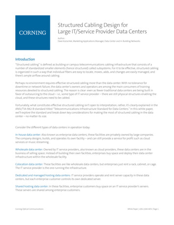
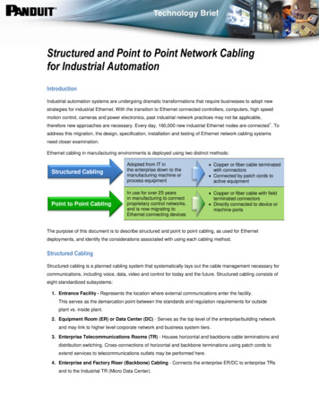
Glossary1. IntroductionProviding an internationally standardized SCS and consolidating cable-deliverymethods for all the systems can reduce initial construction costs for the cablinginfrastructure of a modern intelligent building by up to 30 percent. The actuallevel of savings achieved depends upon the configuration and geographicalpricing for material and labor. This also gives the structure an inherent ability torespond quickly and cost-effectively to the changing needs of tenants, whichimpacts the cost to occupy the space. In some cases, additional constructionexpenditures for the SCS or BMS, such as devices to optimize the use of powerconsumption, may be necessary to reduce the operational expenses. However, thecosts for cabling-related changes can typically be reduced by 25 to 40 percent—with possible savings of up to 60 percent—for a new or renovated facility whenusing a total systems integration approach.As Figure 1 indicates, typical costs for building operation and alterations over a40-year life cycle far exceed the initial construction costs. Proper systemsintegration planning to optimize the construction process can reduce theseongoing life cycle costs.Figure 1. Typical Costs for a SCS2. The Foundation for Systems IntegrationFor many years voice and data systems were cabled separately. Now it is standardpractice to use a common SCS for both of these systems. Like the voice and datasystems of the past, the traditional construction process separately installs eachof the BMS disciplines under various divisions of a specification. The BMStypically consists of the following: fire, life, and safety (FLS) or fire alarm (FA) security and access control (SAC)Web ProForum Tutorialshttp://www.sact-me.comCopyright Sact Communication and networking2/19
energy management systems (EMS) heating, ventilation, and air conditioning (HVAC)These BMS categories are typically cabled separately by the mech anical andelectrical specifications. The voice and data cabling is rarely addressed duringconstruction and is usually not part of the construction budget. Planning andinstallation are normally accomplished when the floor space is being prepared foroccupancy. This means multiple cabling systems and cable delivery methods areinstalled during various stages of the construction.With proper planning, the only limiting factor for complete systems integrationof the voice, data, video, and BMS may be the FA system. In the United States,Article 760-54 (b) of the 1996 National Electrical Code (NEC) allows conductorsof power-limited FA systems and signaling/communications circuits (Article725/800) to share the same cable, enclosure, or raceway. In addition, Article760-61 (d) of the NEC allows the use of the same type of cable for FAs that istypically used for the signaling/communications (voice and data) circuits. Somelocal codes however, especially codes in other countries, may invoke limitationsor require special approvals for integrating the FA system. Yet, even if the FAcabling is installed separately, there are still substantial cost reductions andbenefits that can be derived from integrating the remaining BMS.In addition to the code requirements, there is also a need to evaluate theelectrical characteristics of the systems. The voice and data systems primarilyconsist of analog and digital signals and have established guidelines for signalstrength over distance. The BMS devices operate on current draw, circuitresistance (contact closure), or consist of analog or digital signals. Basically, eachBMS terminal or device will operate over a particular cable type as long as it islocated within a specified range from the equipment.BMS devices are utilized to monitor or control a specific function. This can beequated to an output from the equipment or an input from a device. As anexample, there may be a temperature sensor that gathers information and sendsa signal to the equipment panel (input) and, as a consequence, the equipmentsends a signal to a device that closes a damper or vent (output). Devices areprimarily power -limited or communicate using low-speed protocols. The signaldistance supported by the devices is usually limited by the current draw and linevoltage delivered by the power supply. Typically, 24–American wire gauge(AWG) unshielded twisted-pair (UTP) cable has the capacity to handle 1 Ampere(Amp) of current draw per conductor, with a maximum of 3.3 Amps per four-paircable.What does this mean? The current or signal from the equipment leaves at thespecified voltage level. The device requires a certain voltage level to operate. Asthe signal travels through the cable, the voltage drops due to resistance. CableWeb ProForum Tutorialshttp://www.sact-me.comCopyright Sact Communication and networking3/19
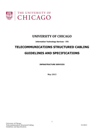
pair resistance is measured by shorting one end of the cable and taking aresistance reading between the conductors at the other end. A typical 24–AWGUTP cable pair has 57.2 Ohms of resistance per one-thousand feet or .0572 Ohmsper foot. Circuit resistance can be measured by dividing the voltage drop by thecurrent draw.If a 24 Volt (V) device requires .05 Amps of current to operate and the allowablevoltage drop is 10 percent, or 2.4V, the maximum circuit distance using 24–AWG UTP cable is 839 feet (256 meters). This can be easily calculated for anycable and circuit using the following two-step formula:1. voltage drop (2.4 V)/current draw (.05 Amps) circuit resistance (48Ohms)2. circuit resistance (48 Ohms)/1 foot cable resistance (.0572 Ohms) maximum distance (839 feet/256 meters)Some equipment vendors state that a lower-gauge cable, such as 18 AWG, isrequired for proper system operation. This is typically found to be unnecessaryonce the electrical characteristics of the system are analyzed.3. PlanningStatements in previous modules of this tutorial have established that it is possibleto use the same type of 24–AWG UTP cable and share a common cable deliverymethod for all power-limited services. The next step is to determine the best wayto perform systems integration. The process starts with early planning and adecision by the building owner or management to select the cabling as the firstsystem. Once the decision is made to use a common cabling infrastructure, it isvery easy to select voice, data, video, and BMS equipment that is compatible withthe cabling. In fact, the sooner the consolidation of cabling systems and deliverymethods is considered, the greater the potential savings and flexibility.The Electronic Industries Association/Telecommunications Industry Association(EIA/TIA) and International Standards Organization/InternationalElectrotechnical Commission (ISO/IEC) have created industry standards forcabling voice and data systems. These standards address the cabling and cabledelivery methods (pathways and spaces) and are based on a structured subsystemarchitecture or cabling elements (see Figure 2). Prior to the standards, thesubsystem concept was first used for voice systems. During the 1980s, it was alsoadopted for data systems. Like the BMS equipment of today, there were manydifferent types of cables and wiring methods for data systems before thestandards were established. Data networks were typically unmanageable, withlittle or no flexibility, and new cabling was often necessary when systems werechanged or upgraded.Web ProForum Tutorialshttp://www.sact-me.comCopyright Sact Communication and networking4/19
Figure 2. Subsystem ArchitectureWith some slight modifications (e.g., use of a coverage ar ea), the EIA/TIA andISO/IEC documents can also be used to provide the same standardized cablingarchitecture for the BMS devices, systems, and applications. The cabling andcable-delivery methods can be designed for all the services with thetelecommunications closet (TC) as the terminating point for horizontal cables.This is the key to the integration of cabling and delivery methods. Thewallfields/distribution frames at the TC location can be combined for maximumflexibility, or individual termination fields can be established within the same TC.Therefore, a secure area for all cabling is created, thus reducing the multiplespaces required for traditional separate installations. Maintenance is alsosimplified since all systems are located in a common area.Standardized cabling architecture allows a single delivery method to be designedfor supporting the various horizontal cables in the work space. It can be taken astep further by incorporating the horizontal electrical services from the electricalpanel into a modular partitioned raceway. This can be used instead of atraditional hardwired installation consisting of several conduit and cable-traysystems for the voice, data, video, BMS, and electrical services. Case studies showthat an integrated approach can provide up to a 30-percent construction savingsfor cabling and delivery methods when a single high/low voltage cablinginfrastructure is implemented. The majority of savings is attributed to thereduction in the amount of labor hours. By reducing labor hours, the space cantypically be occupied at an earlier date. This means saving money by vacatingother leased spaces sooner or collecting additional revenue from tenants that willoccupy the new space.Even if an integr ated high/low voltage raceway system is not utilized, themethods of delivery may be consolidated by using one cable-tray system for all ofthe power-limited services. Conduit can also be provided from the cable tray toprotect critical services. With either choice, with early planning comes the abilityWeb ProForum Tutorialshttp://www.sact-me.comCopyright Sact Communication and networking5/19
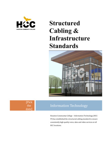
to evaluate all the services and consolidate individual voice, data, video, and BMSusing a single cable type and delivery method instead of multiple cable types anddelivery methods.Figure 3. Separate Systems Approach Using MultipleHardwiredCable-Delivery MethodsFigure 4. Integrated Systems Approach Using Modular Racewayand Open Office CablingThe building's tenants can also realize significant savings. A traditional facilitywith leased space may not provide horizontal cabling for any services. This makesthe setup time for tenants longer. In addition, the tenant usually pays for thevoice and data cabling, along with the cost of occupying the space during setup.The cost and setup time for the tenant can be dramatically reduced by installingWeb ProForum Tutorialshttp://www.sact-me.comCopyright Sact Communication and networking6/19
an open office horizontal cabling grid during the construction phase. Open-officecabling, which is actually another term for prewired zone cabling, provides abuilding with a marketable advantage that could mean the difference betweenempty space and occupied space. One month of full occupancy could pay for theentire cabling system.With open-office cabling fast becoming the preferred method of cabling for bothnew construction and renovations, it is possible to provide a cabling designwithout knowing where any of the devices will be located. The entire design forthe cabling can be based on the maximum usage of the size and type of space. Asan example, a typical voice and data work area for an office can be located every100 square feet (9 square meters), and the BMS devices can be calculated basedon every 250 square feet (23 square meters). Even if an open-office cablingapproach is not utilized, costs can still be reduced by consolidating the cabledelivery methods for the voice, data, video, and BMS services.Historically, voice and data horizontal cabling has not been installed during theconstruction phase. Installing cabling during the construction phase is easier,minimizes damage to finished surfaces, and is reusable for the life of thestructure when designed properly. New cabling does not have to be installedevery time the tenants move, or when systems are changed or upgraded. Thishelpsto eliminate cluttered floor and ceiling spaces. Inaddition, constantrewiring within a structure tends to cause modificationsthatmay affect thephysical structure of the building and the integrity ofthetechnology deployed inthestructure. As seen in Figure 5, systems will changemanytimes during the lifeof astructure. With proper planning, it is not necessary toprovide new cablingeverytime systems are changed or upgraded.Figure 5. Life-Cycle DiagramWeb ProForum Tutorialshttp://www.sact-me.comCopyright Sact Communication and networking7/19
4. Structured Cabling for the BMSsThe SCS can provide up to a 15-percent construction savings for just the BMSinstallation. A traditional installation uses a heavier gauge cable which, per foot,is typically more expensive. An SCS approach provides additional components,such as administration (cross connects), equipment cabling, and a multipairriser. These SCS components, which are part of the SCS subsystem architecture,can make it possible to reduce the number of equipment panels required for theBMS configuration. In addition, since a riser backbone is required for the voiceand data, it is very cost-effective to increase the riser cable size for the BMSservices.The SCS subsystem cabling approach allows the BMS equipment to becentralized, thus fully utilizing all of the available equipment ports. Any powerrequired to operate devices, such as FA strobes or variable volume air boxes, canbe distributed from the TC locations or provided locally. This may necessitateadditional BMS hardware for the SCS approach since 24–AWG cable willtypically power less devices per cable. However, this situation could be alleviatedif BMS power supplies were manufactured with more power taps that suppliedless current per tap. The power taps could even be modular with multipleappearances on a jack, which would also simplify the installation.On the other hand, a traditional BMS installation typically distributes theequipment panels. This leaves many unused ports scattered around a facility andusually requires more equipment panels than a centralized approach. Since thetraditional installation has no administration subsystem, it is neither practicalnor cost-effective to run the device cables to a central equipment location.Centralization of the BMS equipment, which can be used for most structures, ispossible because of the SCS subsystem architecture. This solution can be equatedto a typical private branch exchange (PBX) installation, which uses a centralizedapproach for providing service. A distributed PBX architecture (remote PBXcabinets) will not be used unless the distance limitations are exceeded.Using a distributed equipment approach is typically not cost-effective for mosttypes of equipment or systems. Sometimes the system limitations for datatransmission or power require a distributed topology, but this is usually not thecase for the typical low-speed and power-limited BMS equipment. Using acentralized SCS solution can reduce the combined cabling and equipment costs aswell as reduce the multiple spaces typically required to house the equipment.Web ProForum Tutorialshttp://www.sact-me.comCopyright Sact Communication and networking8/19
Figure 6. Traditional Distributed Approach versus SCSCentralized ApproachInstallation, testing, and the electrical costs for the panels can also be reducedwith a centralized equipment approach. Additionally, if an equipment panel fails,the ports can be easily reconnected to another equipment panel and retranslated.In a traditional installation, the panel—or components within the panel—wouldhave to be replaced in order to restore service. Some vendors state that the panelsmust be placed in close proximity to the mechanical equipment fortroubleshooting, but an RJ45-type outlet can provide plug-in capabilities for aremote hand-held tester. Centralization also allows ports from the sameequipment panel to be dynamically alternated throughout a structure, whichalleviates complete failures on any given floor or area if an equipment panel fails.The subsystem cabling approach also makes upgrades for the BMS equipmentfaster and more cost-effective. In a traditional installation, devices are wiredstraight from the equipment panel to the device. When the panel needs to beupgraded, the cables have to be reterminated in the new panel. This is not alwayseasy or practical, and sometimes the device cables may not be reusable. With thesubsystem cabling approach, at worst, a new equipment subsystem is providedand the devices are reconfigured at the cross connect location. The SCS approachassures economical upgrades to the equipment with minimal service outages.Data-transmission speed is rising as technology advances and more informationis processed. As the BMS equipment becomes more advanced, its associated datatransmission speeds will also increase. Currently, some of the traditional BMScabling will only support limited data rates and applications. If the right cablingis not incorporated into the structure during construction, it may require newcabling in the future.Web ProForum Tutorialshttp://www.sact-me.comCopyright Sact Communication and networking9/19
5. Bid SpecificationsSystems integration can easily be accomplished with the proper bid specificationsand a decision by the building owner, developer, or executive management toselect the cabling system first. Each individual equipment specification shouldprovide, or refer to, an overview of the systems-integration concept and definethe scope of work responsibilities by SCS subsystem for the equipment vendorand cabling contractor. The electrical characteristics of the cabling sh ould also beincluded in the specification to assure systems performance.Once this has been provided, a bid specification for the cabling and deliverymethods can be defined to integrate all the systems. By using this systemsintegration approach, it is possible to reduce each equipment vendor's bid by 20to 30 percent since cabling, delivery methods, and cable-path engineering will beprovided by an integrated cabling specification.6. Integrated SCS Cost Comparison:OverviewThis cost model compares a traditional separate systems installation to a singlydesigned and installed SCS. The approach can be applied to any new or renovatedbuilding project. In this case, the traditional approach uses multiple cable typesand delivery methods. The SCS method uses the same cable type for all the voice,data, video, and BMS services with a common delivery method for all horizontallow-voltage and high-voltage services. The SCS open-office cabling approach alsoprovides for additional horizontal coverage with 599 spare outlets.Table 1. Integrated SCS Cost ComparisonPremisesConfiguration Traditional S
Structured Cabling System (SCS) Definition A structured cabling system (SCS) is a set of cabling and connectivity products that integrates the voice, data, video, and various management systems of a building (such