Transcription
INTRODUCTION TO STRUCTURED CABLINGCompiled bySonam DukdaDivision of Information TechnologyMinistry of CommunicationSeptember 2000
TABLE OF CONTENTS12INTRODUCTION . 4NETWORKING . 52.1Objectives . 52.2Choice of Software and Hardware. 53NETWORKING TRENDS . 64STANDARDS. 64.1International Standards . 64.2Industry Standards. . 64.3Structured Cabling standards. 64.4Highlights of the EIA/TIA-568A standards. 75STRUCTURED CABLING. 85.1Structured Cabling System Design Considerations . 86NETWORK CABLES . 126.1Unshielded Twisted Pair. 126.2Shielded Twisted Pair . 126.3Fiber-Optic Cable . 126.4Evolution of UTP Categories. 13Network Application Primarily Designed to Support . 136.5Category 5E . 146.6Category 6 & 7. 146.7Comparison of Cable Media. 156.8Category Specifications . 157NETWORK SET UP . 167.1Node locations . 167.2Locating Hubs. 167.3Selecting Backbone Routes . 177.4Linking Workgroups at the campus Hub. 177.5Checking Proposed Approach . 197.6Linking Buildings . 197.7Selecting Equipment. 198SYSTEM ADMINISTRATION . 208.1Justification. 208.2Details to Record . 208.3Patching and Jumpering Records. 218.4System Administration . 218.5Maintenance and Repair . 219SOME GUIDELINES. 219.1Unshielded Twisted Pair cable (UTP) separation guidelines from Electro-magneticInterference (EMI) sources. 219.2Minimum bending radius for a cable. 229.3Recommended Cabling Practices. . 229.4UTP cabling installation practices . 239.5Installation of Optical Fiber Connecting Hardware. 239.6Optical Fiber Cabling Installation. 2310 ANNEX I 2411 ANNEX - II. 2411.1 DETAILS – EIA/TIA Cabling Standards. 2511.1.1 EIA/TIA-568A. 2511.1.2 EIA/TIA-569A. 2511.1.3 EIA/TIA TSB-36 . 2511.1.4 EIA/TIA TSB-40A . 2511.1.5 EIA/TIA TSB-53 . 262
11.1.6 EIA/TIA TSB-67 . 2611.1.7 EIA/TIA-606. 2611.1.8 EIA/TIA-607. 2611.1.9 EIA/TIA TSB-72 . 2611.1.10EIA/TIA 526-14 (OFSTP-14). 2711.1.11EIA/TIA 526-7 (OFSTP-7). 2711.2 Standards Under Development . 2711.2.1 TSB-95. 2711.2.2 TIA 568-A-5 . 2711.3 Preliminary Standards Work. 2811.3.1 Category 6 Cabling . 2811.3.2 Category 7 Cabling . 2812 REFERENCES . 283
1INTRODUCTIONDIT recommends the adoption of Structured Cabling standards in the establishment of Networkin the country. This paper is intended to serve as a guideline and introduction to the conceptsinvolved in the issue of structured cabling.Many network administrators keep hearing that the network is down because of some or the otherreason. Various researches indicate that in many cases, the network is down on account of inferiorcabling systems. And installing standards-complaint structured cabling systems can eliminate much ofthis downtime. Another important factor that needs to be taken into account is that the structuredcabling system, though it outlives most other networking components, represents just five percent ofthe total network investment.The structured cable is the only one that needs to be installed to contend with the needs of telephoneand data communications now and in the future. It is a system that provides a very "structured"approach to the entire cabling system—a single-mixed media network that handles all informationtraffic like voice, data, video, and even big complex building management systems. In brief, it couldbe described as a system that comprises a set of transmission products, applied with engineeringdesign rules that allow the user to apply voice, data, and signals in a manner that maximizes data rates.Structured cabling divides the entire infrastructure into manageable blocks and then attempts tointegrate these blocks to produce the high-performance networks that we have now come to rely on.To the user, this means investment protection.In addition to investment protection, structured cabling also provides administrative and managementcapabilities. All cables originating from the different work locations are terminated on a passivecentralized cross-connect in the network room. Simple labeling and colouring mechanisms provide foreasy and quick identification of work outlets. Hence, it provides for a single point for alladministrative and management requirements. Another underlying factor is management of change. Itmust be realized that system architectures keep changing as the system evolves. And the cablingarchitecture should be able to change with minimal inconvenience. The provision of a centraladministrative panel provides the flexibility to make additions, moves, and changes. The changes canbe facilitated with simple switch over of patch cords. Apart from this, structured cabling is alsotechnology independent.The advantages of Structured cabling are: Consistency – A structured cabling systems means the same cabling systems for Data, voiceand video. Support for multi-vendor equipment – A standard-based cable system will supportapplications and hardware even with mix & match vendors. Simplify moves/adds/changes – Structured cabling systems can support any changes withinthe systems. Simplify troubleshooting – With structured cabling systems, problems are less likely to downthe entire network, easier to isolate and easier to fix. Support for future applications – Structured cabling system supports future applications likemultimedia, video conferencing etc with little or no upgrade pain.4
Another primary advantage of structured cabling is fault isolation. By dividing the entire infrastructureinto simple manageable blocks, it is easy to test and isolate the specific points of fault and correctthem with minimal disturbance to the network. A structured approach in cabling helps reducemaintenance costs too.Structured cabling system is fast becoming the norm for small, medium and large networks2NETWORKING2.1ObjectivesThe first step is to establish the aims of network implementation.These might include: 2.2Implementation of administrative and financial databaseStaff access to company recordsAutomation of letter, report or specification writingE-mail for staffStaff schedulingGeneral information automation (including library, plans, graphics and images)Learning or training aids (interactive software)Computer skills training rooms (word processing, publishing, CADD, spreadsheets, databases)Printer sharingFile transferInternet access (graphical, text, news)Access to centralized information sources (e.g. CD-ROM stacks)Automate software updatesCentralize application softwareChoice of Software and HardwareBefore considering network requirements, the machines and software, which are to be networked nowor in the future, must be identified. The purpose of this step is to: Identify which software applications the network operating system and hardware must supportExclude software or machines that will be discarded for other reasons from further networkingconsiderations.After answering the following questions, it should be possible to identify which PC's will initially benetworked, and what existing "legacy" networks should be supported and grafted to the new network.a) Which software packages are proposed to implement the target applications?b) What hardware platform (type, size and speed of PC) will be required to run thesoftware?c) Can existing computers be used, or will they require replacement?d) Can existing computers be upgraded (higher speed CPU, add DOS card to Mac,etc)?5
e) If existing computers require replacement, should they be redeployed to lessdemanding tasks?f) To what extent will expenditure on replacement PC's and software reduce theavailable budget for networking?3NETWORKING TRENDSLocal Area Network (LAN) technology has been available for over fifteen years. The first decade ofLAN technology development was a period in which corporate computing users were graduallyadapting to the new technology and steadily rolling it out within organizations on a department basis.The technology options for implementing corporate LANs during this period consisted primarily of“Ethernet” and “Token Ring” products which would deliver on the average approximately 200 Kbpsto 500 Kbps per user and no more than 10 Mbps to 16 Mbps for an entire network. This first phase ofLAN market growth was characterized by an increasing penetration of LAN technology into corporatecomputing environments.Within the last five years, the corporate computing marketplace has been almost completely convertedto the LAN-based model, with over 80% of all PCs now attached to corporate LANs. As the use ofcorporate LANs for supporting critical business functions has been increased, so has the importance ofspeeding the rate at which these LANs process this critical corporate information. This trend hasrecently fueled the development of multiple new higher speed LAN technologies such as LANswitching, multiple 100 Mbps Ethernet replacements and ATM-the ultimate high speed LAN/WANtechnology.44.1STANDARDSInternational StandardsThe TIA is not the only standards body considering extended performance cabling. The InternationalStandards Organization (ISO) has initiated work on the definition of Category 6 and 7 cabling.Category 6 cabling will specify transmission parameters upto 200 MHZ while Category 7 cable willextend to 600 MHZ. Category 6 and 7 specifications will be included in the second edition of theISO/IEC 11801 standard. However, the definition of Category 6 and 7 is at an early stage with noinput from U.S. at this time. Final ratification is not expected until the year 2000 at the earliest.Reference guide to EIA/TIA Standards are given in Annex I4.2Industry Standards.The advantage of sticking to the industry standards is the knowledge that your cabling will becompatible with standards applications. The disadvantage is that standards organizations seem to taketheir good old time ratifying the standards. The final standard may also be different than the proposedstandard, but the differences are usually minimal. You will often see cable listed as meeting proposedstandards. For example, the proposed standard for Category 6 is 250 MHZ, and the proposed standardfor Category 7 is 600 MHZ.The important thing to remember is this: the proposed standards are improvements over Category5 and Category 5e cable, and should serve you well in terms of speed and headroom for futureapplications.4.3Structured Cabling standardsNetwork managers face a difficult challenge when fitting up a new corporate facility. They mustensure that every possible employee location is accessible to the corporate LAN, but they must alsoensure that each of these locations can successfully work with a potentially broad range of new high6
speed LAN technologies, since these technologies are rapidly gaining in importance and becomingcost effective.The solution to these challenges lies in implementing a structured cabling system within a new facility.Such a system must extend to every employee work area and must be able to support all of the existingLAN technologies and all of the new and emerging high speed LAN technologies, since it isimpossible to predict where within a facility the highest capacity users will be at any time in thefuture.The group, which sets standards for structured data wiring in the United States, is theTelecommunications Industry Association, or TIA. The TIA 568A standard defines multiplecategories or grading of structured wiring system performance, with the category 5 designation as thehighest currently standardized. The TIA 568A category 5 specifications are the basis to which many ofthe new high-speed LAN technologies are targeted.4.4Highlights of the EIA/TIA-568A standardsPurpose To specify a generic voice and data telecommunications cabling systems that will support a multiproduct, multi-vendor environment.To provide direction for the design of telecommunications equipment and cabling productsintended to serve commercial enterprisesTo enable the planning and installation of a structured cabling system for commercial buildingsthat is capable of supporting the diverse telecommunications needs of building occupantsTo establish performance and technical criteria for various types of cable and connecting hardwareand for cabling system design and installationScope Specification are intended for telecommunications installation that are “ Office oriented”Requirements are for a structured cabling system with a usable life in excess of 10 yearsSpecification addressed:(a) Recognized Media – cable and connecting hardware(b) Performance(c) Topology(d) Cabling distances(e) Installation Practice(f) User interface(g) Channel PerformanceCabling Elements Horizontal cabling:a) Horizontal Cross-connect (HC)b) Horizontal Cablec) Transition point (optional)d) Consolidation Point (optional)e) Telecommunications-Outlet (Connector(TO)7
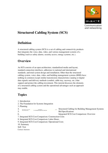
Maximum Distances for Horizontal CablingIn addition to the 90 meters of horizontal cable, a total of 10 meters is allowed for work area andtelecommunications closet patch and jumper cables. Backbone Cabling:a) Main Cross-connect (MC)b) Interbuilding Backbone Cablec) Intermediate Cross-connect (IC)d) Intrabuilding Backbone Cable Work Area (WA) Telecommunications Closet (TS) Equipment Room (ER) Entrance Facility (EF) Administration**** Although administration is addressed to a limited extent, the governing specification ontelecommunications administration is ANSI/EIA/TIA-606.55.1STRUCTURED CABLINGStructured Cabling System Design ConsiderationsThe six subsystem of a Structured Cabling System are
Structured cabling divides the entire infrastructure into manageable blocks and then attempts to integrate these blocks to produce the high-performance networks that we have now come to rely on. To the user, this means investment protection. In addition to investment protection, structured cabling also provides administrative and managementFile Size: 324KB