Transcription
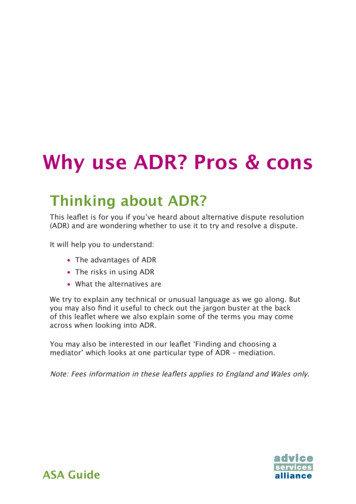
Navigating the Pros and Cons ofStructured Cabling vs. Top of Rack in the Data CenterExecutive SummaryThere is no single end-all cabling configuration for every data center, and CIOs, data center professionals and ITmanagers need to examine the pros and cons of each solution based on their specific needs. This paper focuses onthe many factors to consider when evaluating top of rack (ToR) and structured cabling configurations. Thediscussion includes the impact of those configurations on total management; scalability and upgrades;interoperability; equipment, maintenance and cabling costs; port utilization; power consumption and coolingrequirements.Bandwidth demand and scalability, server virtualization, high-performance switching capabilities and higherdensities necessitate taking a careful look at the various configurations available for cabling a data center. Today’sdata center cabling configuration choices are also impacted by the need to lower power consumption and ensureefficient cooling of critical equipment, as well as by budget constraints and management structure.IntroductionAs data centers become more complex, cabling system design and topology become critical.When the first data centers were built, end user terminals were connected via point-to-point connections. This wasa viable option for small computer rooms with no foreseeable need for growth or reconfiguration. As computingneeds increased and new equipment was added, these point-to-point connections resulted in cabling chaos withassociated complexity and higher cost.In response, data center standards like TIA-942-A and ISO 24764 recommended a hierarchical structured cablinginfrastructure for connecting equipment. Instead of point-to-point connections, structured cabling uses distributionareas that provide flexible, standards-based connections between equipment, such as connections from switches toservers, servers to storage devices and switches to switches (see Figure 1).
Figure 1: TIA-942-A Data Center Topology (similar to ISO24764)With today’s high-performance servers and virtualization, more applications can be delivered from a single rackof servers than ever before. In response, several switch manufacturers recommend a Top of Rack (ToR)configuration where smaller (1RU to 2RU) edge switches are placed in the top of each server rack (or cabinet)and connect directly to the servers in the rack via short preterminated small form-factor pluggable (e.g., SFP andQSFP) twinaxial cable assemblies, active optical cable assemblies or RJ-45 modular patch cords.ToR significantly increases the number of switches and reduces the initial amount of structured cabling. It is oftenrecommended for its rack-at-a-time deployment, ability to limit the use of copper cabling to within racks, supportfor east-west (i.e., server-to-sever) traffic and rack-level management capabilities. Both TIA 942-compliantstructured cabling and ToR have advantages and disadvantages. When selecting the cabling configuration to bestmeet the needs of the data center, it is important to examine the impact that structured cabling and ToR have onoverall total cost of operations, as well as other trade-offs.Manageability ConsiderationsBefore choosing a cabling infrastructure, data center professionals should consider operationalstructure and policies.With structured cabling, patch panels that mirror switch ports and server ports connect to corresponding panels inone or more central patching areas or zones via permanent (or fixed) links. Also referred to as distribution areas,these patching areas may be located at the end or in the middle of a row of cabinets. Moves, adds and changes(MACs) are accomplished by repositioning patch cord or fiber jumper connections at the central patching area.The fixed portion of the channel remains unchanged and switches and equipment are left untouched and secure.This creates an “any-to-all” configuration where any switch port can be connected to any equipment port.Furthermore, structured cabling can be field terminated to any length to maintain a clean, slack-free appearance.
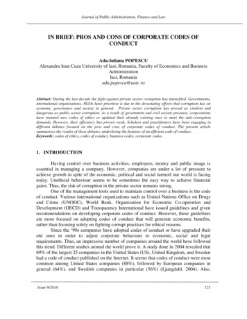
In a ToR configuration, switches at the top of each rack connect directly to the servers in the same rack, requiringall changes to be made within each individual rack (or cabinet). This eliminates the use of central patching andreduces the amount of structured cabling in the data center (see Figure 2). MACs in a ToR configuration can bemore complicated and time consuming—especially in large data centers with hundreds of cabinets. Changes mustbe made in individual racks or cabinets, rather than at one convenient central patching area. Identifying thespecific rack or cabinet requiring the change can be a complicated process.ToR can be a solution for data centers where individual racks of servers and their corresponding switches need tobe managed as their own entity or segregated by application. ToR does not allow network administrators to keepswitches separate from server administrators, which can be problematic when these groups manage switches andservers separately and when switches must remain protected for security purposes.Figure 2: Structured Cabling vs. ToR Topology. ToR eliminates central patching in the distribution area.Note: Designs based on a three-tier switch architecture.Scalability and Upgrade ConsiderationsCabling system design can limit or enhance squeezing the most from racks, servers and ports.A widespread switch upgrade with ToR impacts many more switches than with structured cabling and requiresequipment at the network core to have the port densities and bandwidth capacity to support the increased numberof switches. An individual switch upgrade with structured cabling can increase connection speeds to multipleservers across several racks in the data center. An upgrade to an individual ToR switch improves connectionspeed to only the servers in that rack.ToR switches using short-distance small form-factor pluggable twinaxial cable assemblies cannot supportautonegotiation. Because the twisted-pair cabling used with structured cabling is backwards compatible, itsupports autonegotiation where individual ports can switch between a 10 and 1 gigabit operation depending on theconnected equipment. Autonegotiation enables partial switch or server upgrades on an as-needed basis, enabling acost-effective migration over time. Without autonegotiation, a switch upgrade requires all equipment connected tothat switch to be upgraded simultaneously, incurring full upgrade costs all at once.
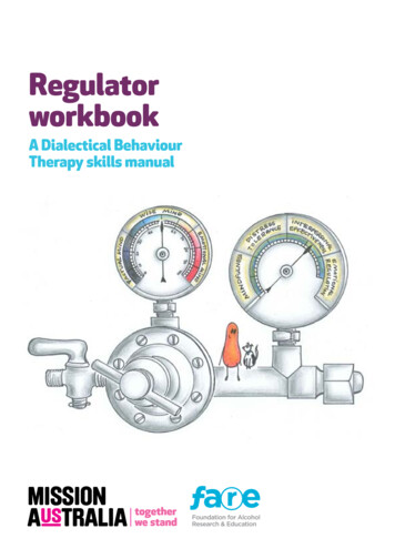
Because ToR small form-factor pluggable twinaxial cable assemblies are typically more expensive than copperpatch cords in a structured cabling system, costs can escalate even further during upgrades as some equipmentvendors require use of their cable assemblies and force cable upgrades with equipment upgrades. The corephysical layer infrastructure or the fixed portion of the cabling channel is typically installed once, as long as theminimum standards recommended fiber and copper cabling are used.In a ToR configuration using small form-factor pluggable twinaxial cable assemblies, distance between theswitches and the servers is limited to a length of 7 meters in passive mode. While this is not a problem if eachrack will always be managed as an individual unit, these short lengths can restrict the location of equipment ifneeds change. Structured cabling lengths can be up to 100 meters, allowing flexible equipment placement.Interoperability ConcernsOpen systems enable more choices and a competitive market place.Interoperability and the open systems concept is the “bedrock” of cabling industry standards. Data centermanagers expect and value interoperability to fully leverage their existing cabling investment by ensuringperformance and a competitive market regardless of which vendors’ equipment and cable designs are selected.Unfortunately, some switch vendors now require their proprietary cable assemblies for connecting ToR switchesto servers when using small form-factor pluggable twinaxial cable assemblies. Some ToR switches are designedto check vendor security IDs on cables and either display errors or prevent ports from functioning when connectedto an unsupported vendor ID. While this helps ensure that vendor-approved cable assemblies are used withcorresponding electronics, it can limit data center design options by locking data center managers into aproprietary solution. This is a substantial change from the industry standards-based fiber connectivity and copperconnectivity successfully deployed in data centers for decades.Third-party independent testing by University of New Hampshire's Interoperability Lab (UNH IOL) proves thatpassive small form-factor pluggable twinaxial cable assemblies from cabling vendors pass interoperability testingwith several vendors’ ToR switches that are designed to display errors. These tests demonstrate that proprietarycables are not necessarily required. This may not be the case for switches designed to actually prevent ports fromfunctioning altogether when connected to an unsupported vendor ID.Maintenance, Equipment and Cabling CostThe choice of cabling system has a major impact on cost.With a ToR switch in every cabinet (or two for dual primary and secondary networks), the total number of switchports depends on the total number of cabinets in the data center, rather than on the actual number of switch portsneeded to support the equipment. This can nearly double the amount of switches and power supplies required,compared to structured cabling. Unlike passive structured cabling, ToR switches require power and ongoingmaintenance. For example, based on an actual 39-cabinet data center using separate dual networks, the cost forequipment and maintenance for ToR is more than twice that of structured cabling (see Figure 3).The use of distribution areas with structured cabling also impacts cabling costs. ToR saves on structured cablingcosts, but the added cost of cabling assemblies can negate that savings, especially when switch vendors requiretheir proprietary cable assemblies. As shown in Figure 3, the cost of the ToR cable assemblies for each used portis more than twice the cost of structured cabling. Even if the cost of ToR cable assemblies is not a consideration,structured cabling costs represents only about five percent of the total equipment and maintenance savingsrealized with structured cabling. Structured cabling also typically carries a 15 to 25 year warranty (depending onmanufacturer) as opposed to the average 90-day warranty on cabling assemblies offered by most electronicsvendors.
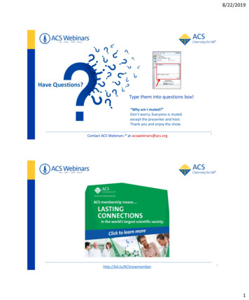
Equipment and Unit PriceToRUnitsPriceStructured CablingUnitsPriceTotal Savings32-port 10G ToR Switches ( 15,000)78 1,170,00035 525,000 645,000Redundant Power Supplies ( 500)78 39,00035 17,500 21,500SFP Uplink Ports ( 1500)312 468,000140 210,000 258,00032-Port Aggregation Switches ( 25,000)10 250,0005 125,000 125,000SFP Modules ( 5000)80 400,00040 200,000 200,000Redundant Power Supplies ( 500)10 5,0005 2,500 2,5002 160,0002 160,0000Redundant Power Supplies at ( 7,500)2 15,0002 15,0000Fiber Cards for Uplinks at ( 70,000)4 280,0002Core Switches ( 80,000) 140,000 140,000 240,000 110,000 130,000Equipment Total (not including software) 2,787,000 1,395,000 1,392,0003 Years Maintenance 1,200,000 570,000 630,000Cabling TotalTOTAL 4,227,000 2,075,000 2,152,000Figure 3: ToR vs. Structured Cabling Cost Comparison (based on MSRP at time of print) for an actual 39-cabinetdata center (assumes average 5 to 6kW per cabinet, dual network, redundant power supplies, 14 servers per cabinet,four uplinks per switch, 2.5-meter SFP direct attach cable assemblies for each used ToR port, and category 6A UTPfor structured cabling).Furthermore, a ToR design can add to server costs. Servers with twisted-pair network interface cards (NICs) aretypically less expensive than those with SFP or QSFP NICs. Many server platforms also ship with twisted-paircopper NICs native to the motherboard. With ToR deployments supported by small form-factor pluggabletwinaxial cable assemblies, SFP or QSFP NICs would need to be purchased for those connections, which canrange from about 400 to 800 per NIC.Switch Port UtilizationStructured cabling maximizes port accessibility and utilization.Studies by DataCenter Dynamics and the Gartner Group show that the average power supplied to a server cabinetranges between 5 and 6kW. Using this assumption, the number of servers in a cabinet is approximately 14. Serverswitch port demand is therefore typically lower than the switch ports available on a ToR switch. For example,with only 14 ports of a 32-port switch used, 18 ports will remain unused. Other assumptions using a highernumber of servers and higher power supplied to the server cabinet would improve the switch port utilization on aToR switch. The relative economics would need to be determined based on the actual design and type of serversthat are deployed.When using separate dual networks with 14 servers per cabinet where each server connects to two 32-portswitches, 28 of the 64 ports are used for the 14 servers, leaving 36 unused. When applied across the actual 39cabinet example used in Figure 3, this scenario results in 1,404 unused ports, which equates to nearly 44unnecessary switch purchases (see Figure 4).With structured cabling, virtually all active ports can be fully utilized because they are not confined to singlecabinets. Instead, the 32 switch ports that would be dedicated to a single cabinet in the ToR configuration can nowbe divided up, on demand, to any of several cabinets via the distribution area. Even if edge switches are used toaccommodate east-west (i.e., server-to-server) traffic, structured cabling allows the switches to be centrallylocated in distribution areas, which decreases the number of unused ports and reduces the amount of north-southtraffic to and from aggregate and core switches.
ToREquipmentStructured alPortsUsedPortsUnusedPorts32-port 10G ToR Switches7824961092140435112010922832-Port Aggregation Switches103203128516014020Fiber Cards for Core Uplinks412840882642044TOTAL PORT USAGE2944144415001344125292Figure 4: Switch port utilization for ToR vs. Structured Cabling for an actual 39-cabinet data center (assumes average 5 to6kW per cabinet, dual network, redundant power supplies, 14 servers per cabinet and four uplinks per switch ).While the number of unused ports will be less in high-density server environments where the power supplied toserver cabinets is now reaching upwards of 20kW to support a full complement of servers, they can still add up.For example, in a 200-cabinet high-density server farm with 40 servers and a 48-port switch per cabinet, thenumber of unused ports reaches 1600 (i.e., 8 unused ports per cabinet) at a cost of about 735,000. Usingstructured cabling can save nearly 85% even in these high-density environments. Being able to effectively manageunused switch ports is therefore a key consideration when selecting a ToR configuration. It is worth noting thatsome data centers use a switch fabric architecture, which may have a different outcome on the number of unusedports and amount of equipment and cabling compared to a three-tier switch architecture. However, the benefits ofa structured cabling system remain.Increased Power ConsumptionPort utilization and equipment have a major impact on power consumption.Power consumption is one of the top concerns among today’s data center managers as energy costs continue torise, power becomes more costly and green initiatives take center stage. As shown in Figure 5 below, the ability touse all switch ports with structured cabling lowers the number of switches and power supplies required by morethan half. This helps cut equipment and energy costs while contributing to “green” initiatives such as LEED,BREEAM or STEP. With structured cabling requiring fewer power supplies, future upgrades to more efficientpower supplies are easier and more cost effective.ToRStructuredCabling7835Redundant Power Supplies7835SFP Uplink Ports312140105SFP Modules8040Redundant Power Supplies10522Redundant Power Supplies22Fiber Cards for Uplinks at42Equipment32-port 10G ToR Switches32-Port Aggregation SwitchesCore Switches)TOTAL SWITCHES9042TOTAL POWER SUPPLIES9042Figure 5: With structured cabling, the number of switches and power supplies required is less than half that of ToR, therebyreducing power consumptionWhen switches reach full utilization in a ToR configuration, adding a new server to the cabinet requires anadditional switch in the cabinet as well as additional power supplies. This can take away from potential power that
can be allocated for servers. There may not even be enough power provisioned to the cabinet to support theadditional load. Even with virtualization reducing the number of servers and related power and cooling, theincreased number of power supplies required with ToR can potentially negate some virtualization savings.It is important to remember that even in an idle state, unused switch ports can consume power. Furthermore, edgeswitches like those used in ToR process more instructions in their central processing units. This can causepotential unanticipated power spikes. Regardless of the configuration and technologies deployed, powerconsumption varies by switch model and manufacturer and actual port consumption or power draw should beexamined across the entire data center.Cooling and Failure Rate ConsiderationsImproper placement of equipment can wreak havoc on the best data center cooling and uptime plan.While a ToR switch can technically be placed in the middle or bottom of a cabinet, they are most often placed atthe top for easier accessibility and manageability. According to the Uptime Institute, the failure rate for equipmentplaced in the top third of the rack is three times greater than that of equipment located in the lower two thirds. In astructured cabling configuration, the passive components (i.e., patch panels) are generally placed in the upperposition, leaving the cooler space for the equipment.ToR designs can also land-lock equipment placement due to the short cabling lengths available and data centerpolicies that do not allow patching from cabinet to cabinet. This can prevent placing equipment where it makesthe most sense for power and cooling. For example, if the networking budget does not allow for outfitting anothercabinet with a ToR switch, placement of a new blade server may be limited to where network ports are available.This can lead to hot spots, which can adversely impact neighboring equipment within the same cooling zone.Structured Cabling systems avoid these problems.ConclusionMany factors impact the choice of which cabling configuration to deploy, and there is no single end-all solution.ToR configurations can make a lot of sense for small server rooms, when self-contained cabinets are required orwhere a higher number of unused ports can be managed. However, data center managers should carefully considerthe pros and cons as outlined in Figure 6.ToR Pros Reduced amount of structured cablingLower cabling infrastructure costsRack-based cable management and changesRack-based access for application segregationRack-based switch upgradesToR Cons Significantly higher equipment, maintenance and cabling costsPoor port utilizationIncreased power consumptionScalability and upgrade limitations – may not supportinteroperability and autonegotiation Time consuming MACs in large data centers Limited equipment placement and potential hot spotsFigure 6: ToR Pros and ConsWhen selecting a cabling configuration for the data center, an overall study that includes total management;scalability and upgrades; interoperability; equipment, maintenance and cabling costs; port utilization; and powerand cooling requirements should be undertaken by facilities and all networking departments to ultimately makethe best educated decision. ToR is often positioned as a replacement for structured cabling, but in many instances,structured cabling must coexist with ToR to support central switching for KVM or other in-band or out-of-bandmanagement and data center monitoring.
In response, data center standards like TIA-942-A and ISO 24764 recommended a hierarchical structured cabling infrastructure for connecting equipment. Instead of point-to-point connections, structured cabling uses distribution areas that provide flexible, standards-based connections between equipment, such as connections from switches to .