Transcription
UNESCO-NIGERIA TECHNICAL &VOCATIONAL EDUCATIONREVITALISATION PROJECT-PHASE IINATIONAL DIPLOMA INBUILDING TECHNOLOGYTECHNICAL DRAWINGCOURSE CODE: BLD 107YEAR I- SE MESTER ITHEORY/PRACTICALVersion 1: December 2008
WEEK 1 DRAWING EQUIPMENT1.1 Equipment1.2 Types of Lines1.3 Application of TypesWEEK 2 DRAWING SCALES AND LETTING METHOD2.1 Drawing Scales2.2 Lettering MethodsWEEK 3 CIRCLES AND POLYGONS3.1 Circles3.2 Properties of A Circle3.3 PolygonsWEEK 4 LOCI4.1parabola4.2 Hyperbola4.3 EllipseWEEK 5 PROJECTION5.1 Orthographic Projection5.2 Multi views Projection5.3 Differences Between First and Third Angle ProjectionWEEK 6 ISOMETRIC AND OBLIQUE PROJECTIONS6.1 Isometric Projections6.2 Oblique Pictorial ProjectionsWEEK 7 PERSPECTIVE DRAWING7.1 One- Point Perspective7.2 Two Point Perspective7.3 Three-Point PerspectiveWEEK 8 DIMENSIONS FOR TECHNICAL DRAWING8.1 Types Of Dimensioning Techniques
8.2 Chain Dimensioning8.3 Dimensioning Small Features8.4 Dimensioning Circles8.5 Dimensioning Radius8.6 Simplified Dimensioning by Co-Ordinates8.7 Arrangement of DimensionsWEEK 9 ABBREVIATIONS IN SYMBOLS USED IN MECHANICAL,ELECTRICAL AND BUILDING DRAWING9.1 Technical Drawing Symbols9.2 Conventional Symbols9.3 Line and Block DiagramsWEEK 10 FREE HAND SKETCHING10.1General Notes Before SketchingWEEK 11 SKETCHING THE VIEW FROM AND ACTUAL OBJECT11.1Oblique SketchingWEEK 12 THE MAIN FEATURES OF THE SIX VIEW OF AN OBJECTWEEK 13 MISSING VIEW13.1First Angle Projection13.2Third Angle of ProjectionWEEK 14 INTERSECTION OF SOLIDSWEEK 15 SURFACE DEVELOPMENT OF SOLIDS15.1Surface Development of Diagonal Box15.2Surface Development of a Hexagonal Box15.3Development of an Oblique Hexagonal Tube15.4Development of a Hexagonal Prism Cut By a Plan15.5Development of a Hexagonal Prism Cut By a Plane15.6Development of an Oblique Circular Tube15.7Development of a Cylindrical Cut By a Plane
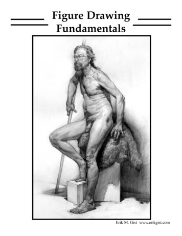
WEEK 1: DRAWING EQUIPMENTIntroductionTechnical drawing is concerned mainly with using lines, circles, arcs etc., to illustrate generalconfiguration of an object. It is a language of communication between architects andEngineers, usually to convey information about the object. However, it is very important thatthe drawing produced to be accurate and clear.The ability to read and understand drawings is a skill that is very crucial for technicaleducation students; this text aims at helping students to gain this skill in a simple and realisticway, and gradually progress through drawing and interpreting different level of engineeringdrawings.1.1 EquipmentSome basic equipment is necessary in order to learn drawing effectively, here are the mainones.o T-square:A T-square is a technical drawing instrument primarily used for drawing horizontal lines on adrafting table, it is also used to guide the triangle that is used to draw vertical lines. The name“T-square” comes from the general shape of theinstrument where the horizontal member of the T(blade) slides on the side of the drafting table. Figure(1.1)(Fig.1.1)o Set- square:A set square or triangle is a tool used to draw straightvertical lines at a particular planar angle to a baseline.The most common form of Set Square is a triangularpiece of transparent plastic with the centre removed.The outer edges are typically beveled. These setsquares come in two forms, both right triangles: onewith 90-45-45 degree angles, and the other with90-60-30 degree angles. Figure (1.2)o Compass:(Fig.1.2)
Compasses are usually made of metal, and consist of two parts connected by a hinge whichcan be adjusted. Typically one part has a spike at its end, andthe other part a pencil. Circles can be made by pressing oneleg of the compasses into the paper with the spike, putting thepencil on the paper, and moving the pencil around whilekeeping the hinge on the same angle. The radius of the circlecan be adjusted by changing the angle of the hinge. Figure (1.3)(Fig.1.3)o Drawing table:It is a multi-angle desk which can be used in different angleaccording to the user requisite. The size suites most papersizes, and are used for making and modifying drawings onpaper with ink or pencil. Different drawing instruments suchas set of squares, protractor, etc. are used on it to drawparallel, perpendicular or oblique lines. Figure (1. 4)(Fig.1.4)o Irregular Curves (French curves):French curves are used to draw oblique curves other thancircles or circular arc, they are irregular set of templates.Many different forms and sizes of curve are available.Figure (1. 5)(Fig.1. 5)
(Fig. 1.6)o Protractor:The Protractor is a circular or semi-circular tool for measuring angles. The units ofmeasurement used are degrees. Some protractors are simple half-discs. More advancedprotractors usually have one or two swinging arms, which can be used to help measuringangles. Figure (1. 6)o Drawing Pencil:This is a hand-held instrument containing an interiorstrip of solid material that produces marks used to writeand draw, usually on paper. The marking material ismost commonly graphite, typically contained inside awooden sheath. Mechanical pencils are nowadays morecommonly used, especially 0.5mm thick Figure (1. 7)(Fig.1. 7)o Eraser:Erasers are article of stationery that are used forremoving pencil writings. Erasers have made ofrubbery material, and they are often white. Typicalerasers are made of rubber, but more expensive orspecialized erasers can also contain vinyl, plastic, orgum-like materials. Figure (1. 8)(Fig.1. 8)
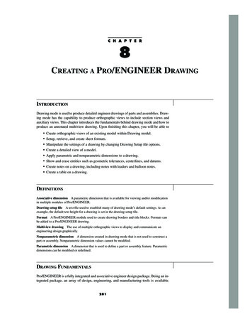
1.2 Types of Lines:Usually lines created are all of the same thickness and type, but lines on an engineeringdrawing signify more than just the geometry of the object, and it is important that appropriateline type is used in the right place, because each gives different meaning.o Line ThicknessFor most engineering drawings two thicknesses of lines are mainly required, a thick and thinone. The general recommendations are that thick lines to be twice as thick as the thin lines.A thick line is used for visible leader edges andoutlineA thin line is used for hatching, lines, short centre lines, dimensionsand projections.o Line StylesLine styles are used to clarify important features on drawings, some examples are as shownbelow. Figure (1. 9)(Fig.1. 9) – Line styles and typesLine styles are used to graphically represent physical objects, and each has its own meaning,these include the following: Visible lines - are continuous lines used to draw edges directly visible from aparticular angle.Hidden lines- are short-dashed lines that may be used to represent edges that are notdirectly visible.
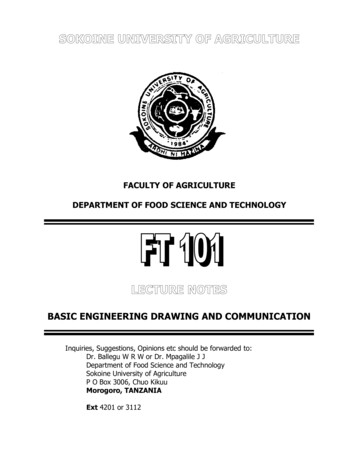
1.3 Application of Types of Lines(Fig.1.10)Thick long chain line witharrow heads for sectioningRuled line with zig-zagsto show continuityThin short dashes toindicate hidden detailsThick continuous line foroutline of an object(Fig. 1.11)
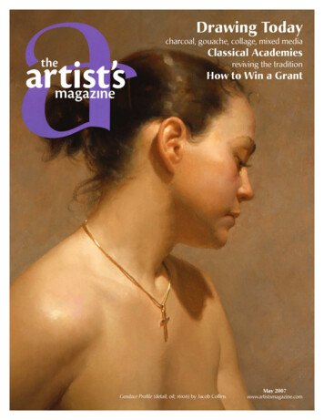
WEEK 2: DRAWING SCALES AND LETTERING METHODS2.1 Drawing ScalesGenerally, it is easier to produce and understand a drawing if it represents the true size of theobject drawn. This is of course not always possible due to the size of the object to be drawn,that is why it is often necessary to draw enlargements of very small objects and reduce thedrawing of very large ones, this is called “SCALE”.However, it is important when enlarging or reducing a drawing that all parts of the object areenlarged or reduced in the same ratio, so that the general configuration of the object is saved.Thus, scales are multiplying or dividing of dimensions of the object.The scale is the ratio between the size represented on the drawing and the true size of theobject.Scale Dimension to carry on the drawing True Dimension of the object.Examples:1. Dimension carried on the drawing 4mm.True dimension 40mmScale 4 40 1:102. Calculating drawing dimension of a line having a true dimension of 543 mm to a scaleof 1/10. If a true dimension of 10mm is represented as 1mm, a true dimension of543mm is represented as X Then 10 mm ----------------Æ 1 mm543 mm----------------Æ X mm We have 1/10 x 543 or X 54.3mm.Therefore, a true dimension of 543mm is represented to a scale of 1/10 by a length of54.3mm.
(Fig.2. 1) An example of scaling a drawing2.2 Lettering MethodsLettering is more as freehand drawing and rather of being writing. Therefore the sixfundamental strokes and their direction for freehand drawing are basic procedures forlettering.There are a number of necessary steps in learning lettering, and they include the following: Knowledge of proposition and form of letters and the orders of the stroke. Knowledge of the composition the spacing of letters and words. Persistent practices.Capital letters are preferred to lower case letters since they are easier to read on reduced sizedrawing prints although lower case letters are used where they from of a symbol or anabbreviation.Attention is drawn the standard to the letters and characters. Table (2.1) below give therecommendation for minimum size on particular drawing sheets:
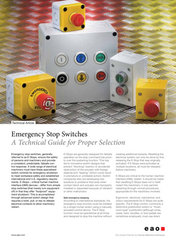
Table (2.1) Recommendations for minimum size of lettering on drawing sheetsApplicationDrawing numbers, etc.Dimension and notesDrawing Sheets SizeMinimum character heightA0, A1, A2 and A35 mmA43 mmA03.5 mmA1, A2, A3 and A42.5 mmThe spaces between lines of lettering should be consistent and preferably not less than half ofthe character height.There are two fundamental methods of writing the graphic languages freehand and withinstruments. The direction of pencil movements are shown in Figure. (2.2) and (2.3).
Vertical Capital Letters & Numerals(Fig.2.2) Vertical Capital Letters and Numerals(Fig.2.3) Vertical lower case letter
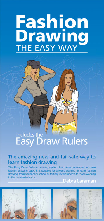
Quiz Sheet (2):31Reproduce Figure (2.4) to a scale of 1:5.2Redraw Figure (2.5) to a scale of 3:1.On a drawing sheet copy the following text in Figure (2.4) using the correct letteringmethods:
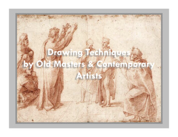
WEEK3: CIRCLES AND POLYGONS3.1 Circleso DefinitionA circle is a plane figure bounded by a curved line called the circumference, which is always equidistantfrom the centre.3.2 PROPERTIES OF A CIRCLE A diameter is a straight line drawn through the centre meeting the circumference at bothends. A radius is a straight line drawn from the centre to the circumference. An arc is part of the circumference. A chord is any straight line drawn across the circle meeting the circumference at both ends. A tangent is a straight line which touches the circumference. It is always at right angles tothe radius. A segment is part of a circle bounded by an arc and a chord. A sector is a part of a circle bounded by two radii and an arc. A quadrant is part of a circle bounded by two radii at right angles and an arc. Concentric circles are circles of the same centre but different radii Eccentric circles are circles of different centres(Fig. 3.1)(Fig. 3. 2 )
Fig. 3.3 Concentric CirclesFig. (3.4 Eccentric Circles3.3 Polygonso DefinitionsA polygon is a plane figure bounded by more than four straight sides. Polygons arefrequently referred to have particular names. Some of these are listed below A pentagon is a plane figure bounded by five sides A hexagon is a plane figure bounded by six sides A heptagon is a plane figure bounded by seven sides An octagon is a plane figure bounded by eight sides A nonagon is a plane figure bounded by nine sides A decagon is a plane figure bounded by ten sides. A regular polygon is one that has all its sides equal and therefore all its exterior anglesequal and all its interior angles equal. The diameter of that circle is called the diameter of the polygon.
The diagonal of a polygon is the distance from one corner to the corner furthest awayfrom it.o To construct a regular octagon given the diagonal, i.e. within a given circleSteps Draw the circle and insert a diameter AE. Construct another diagonal CG, perpendicular to the first diagonal. Bisect the four quadrants thus produced to cut the circle in B, D, F, and H.ABCDEFGH is the required octagon.(Fig. 3.3.)o To construct a rectangular octagon; given the diameter, i.e, within a givensquare. Construct a square PQSR, length of side equal to the diameter. Draw the diagonals SQ and PR to intersect in T. With centres P, Q, R, and S draw four arcs, radius PT ( QT RT ST) to cut thesquare in A, B, C, D, E, F, G and H.ABCDEFGH is the required octagon.
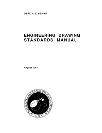
Fig.3.4o To construct any given polygon; given the length of a side.There are three fairly simple way of constructing a regular polygon. Two methods require asimple calculation and the third requires very careful construction if it is to be exact. All threemethods are shown. The constructions work for any polygon, and a heptagon (seven sides)has been chosen to illustrate themMethod 1 Draw a line AB equal in length to one of the sides and produce AB to P. Calculate the exterior angle of the polygon by dividing 3600/7 51 30/7. Draw the exterior angle PBC so that BC AB. Bisect AB and BC to intersect in O. Draw a circle, centre O and Radius OA ( OB OC). Step off the sides of the figure from C to D, D to E, etc. ABCDEFG is requiredheptagon.
(Fig.3. 5)Method 2 Draw a line AB equal in length to one of the sides From a, erect a semi –circle, radius AB to meet BA produced in P. Divide the semi circle into the same number of equal parts as the proposed polygonhas sides. This may be done by trial and error or by calculation (1800 /7 25 50/7 foreach arc). Draw a line from A to point 2 (For all polygons). This forms a second side to thepolygon. Bisect AB and A2 to intersect in O. With centre O draw a circle, radius OB ( OA O2). Step off the sides of the figure from B to C, C to D etc.ABCDEFG is the required septagon.
(Fig.3. 6)Method 3 Draw a line GA equal in length to one of the sides Bisect GA From A construct an angle of 450 to intersect the bisector at point 4. From G construct an angle of 600 to intersect the bisector at point 6. Bisect between points 4 and 6 to give point 5.Point 4 is the centre of the circle containing a square. Point 5 is the centre of a circlecontaining a pentagon. Point 6 is
Lettering is more as freehand drawing and rather of being writing. Therefore the six fundamental strokes and their direction for freehand drawing are basic procedures for lettering. There are a number of necessary steps in learning lettering, and they include the following: Knowledge of proposition and form of letters and the orders of the stroke. Knowledge of the composition the spacing .