Transcription
HPE ProLiant ML30 Gen10 Server User GuidePart Number: 30-2564CC28-005Published: June 2021Edition: 5
HPE ProLiant ML30 Gen10 Server User GuideAbstractThis document is for the person who installs, administers, and troubleshoots servers and storage systems. Hewlett Packard Enterpriseassumes you are qualified in the servicing of computer equipment and trained in recognizing hazards in products with hazardous energylevels, and are familiar with the weight and stability precautions for rack installations.Part Number: 30-2564CC28-005Published: June 2021Edition: 5 Copyright 2018–2021 Hewlett Packard Enterprise Development LPNoticesThe information contained herein is subject to change without notice. The only warranties for Hewlett Packard Enterprise products andservices are set forth in the express warranty statements accompanying such products and services. Nothing herein should be construed asconstituting an additional warranty. Hewlett Packard Enterprise shall not be liable for technical or editorial errors or omissions containedherein.Confidential computer software. Valid license from Hewlett Packard Enterprise required for possession, use, or copying. Consistent with FAR12.211 and 12.212, Commercial Computer Software, Computer Software Documentation, and Technical Data for Commercial Items arelicensed to the U.S. Government under vendor's standard commercial license.Links to third-party websites take you outside the Hewlett Packard Enterprise website. Hewlett Packard Enterprise has no control over and isnot responsible for information outside the Hewlett Packard Enterprise website.AcknowledgmentsLinux is the registered trademark of Linus Torvalds in the U.S. and other countries.Microsoft , Windows , and Windows Server are either registered trademarks or trademarks of Microsoft Corporation in the United Statesand/or other countries.Red Hat Enterprise Linux are registered trademarks of Red Hat, Inc. or its subsidiaries in the United States and other countries.VMware ESXi and VMware vSphere are registered trademarks or trademarks of VMware, Inc. and its subsidiaries in the United States andother jurisdictions.All third-party marks are property of their respective owners.
Table of contents1 Component identification1.1 Front panel components1.2 Front panel LEDs and button1.2.1 Front panel LED power fault codes1.3 Rear panel components1.4 Rear panel LEDs1.5 System board components1.5.1 System maintenance switch descriptions1.5.2 DIMM label identification1.5.3 DIMM slot locations1.5.4 PCI expansion slot definitions1.6 Drive LEDs and buttons1.6.1 Low-profile LFF drive LED definitions1.6.2 Smart Carrier (SC) drive LED definitions1.7 Drive bay numbering1.8 Fan numbering1.8.1 Fan mode behavior1.9 Media device screws2 Operations2.1 Power up the server2.2 Power down the server2.3 Extend the server from the rack2.4 Remove the server from the rack2.5 Slide the server into the rack2.6 Remove the front bezel2.7 Install the front bezel2.8 Remove the access panel2.9 Install the access panel2.10 Remove the air baffle2.11 Install the air baffle2.12 Remove the PCI slot blank retainer2.13 Remove the PCI slot blank2.14 Position the tower server for hardware configuration2.15 Position the tower server for operation3 Setup3.1 Initial system installation3.1.1 HPE Installation Service3.1.2 Setting up the server3.2 Operational requirements3.2.1 Space and airflow requirements3.2.2 Temperature requirements3.2.3 Power requirements
3.2.4 Electrical grounding requirements3.3 Rack warnings and cautions3.4 Server warnings and cautions3.5 Electrostatic discharge3.6 POST screen options4 Hardware options installation4.1 Hardware option installation guidelines4.2 Tower to rack conversion kit4.2.1 Installing the tower-to-rack conversion kit4.2.2 Preparing the server for rack installation4.2.3 Installing the rack rails and server tray4.2.4 Installing the server on the tray4.3 Installing the PCI fan and air baffle options4.4 Power supply options4.4.1 Hot-plug power supply calculations4.4.2 Power supply warnings and cautions4.4.3 Flexible Slot (Redundant) power supply enablement option4.4.3.1 Installing a Flexible Slot (Redundant) power supply enablement option4.5 Drive options4.5.1 Drive installation guidelines4.5.2 Drive support information4.5.3 Installing an LFF non-hot-plug drive in the drive cage4.5.4 Installing an LFF hot-plug drive4.5.5 Installing an SFF hot-plug drive4.6 Media device options4.6.1 Installing a SAS LTO tape drive4.6.2 Installing a USB RDX drive4.6.3 Installing an optical drive4.6.4 Installing an LFF non-hot-plug drive in the media drive bay4.7 Memory options4.7.1 DIMM population information4.7.2 Installing a DIMM4.8 M.2 SSD/dedicated iLO/serial port enablement option4.8.1 M.2 SSD/dedicated iLO/serial port enablement option components4.8.2 Installing the M.2 SSD/dedicated iLO/serial port enablement board4.8.3 Installing the serial port cable4.8.4 Enabling the dedicated iLO management module4.9 M.2 SSD option4.9.1 Installing an M.2 NVMe SSD on the system board4.9.2 Installing an M.2 NVMe SSD on an M.2 SSD/dedicated iLO/serial port enablement board4.10 Storage controller options4.10.1 Installing a Smart Array standup storage controller4.11 Energy pack options4.11.1 HPE Smart Storage Battery
4.11.2 HPE Smart Storage Hybrid Capacitor4.11.2.1 Minimum firmware versions4.11.3 Installing an energy pack4.12 Expansion board options4.12.1 Expansion board thermal requirement4.12.2 Installing an expansion board4.13 Internal USB device option4.13.1 Installing an internal USB device4.14 HPE Trusted Platform Module 2.0 Gen10 option4.14.1 Overview4.14.2 HPE Trusted Platform Module 2.0 guidelines4.14.3 Installing and enabling the HPE TPM 2.0 Gen10 option4.14.3.1 Installing the Trusted Platform Module board4.14.3.1.1 Preparing the server for installation4.14.3.1.2 Installing the TPM board and cover4.14.3.1.3 Preparing the server for operation4.14.3.2 Enabling the Trusted Platform Module4.14.3.2.1 Enabling the Trusted Platform Module as TPM 2.04.14.3.2.2 Enabling the Trusted Platform Module as TPM 1.24.14.3.3 Retaining the BitLocker recovery key/password5 Cabling5.1 Cabling guidelines5.2 Storage cabling5.2.1 LFF non-hot-plug drive cabling from the media bay5.2.2 LFF non-hot-plug drive cabling from the drive cage5.2.3 LFF hot-plug drive cabling5.2.4 SFF hot-plug drive cabling5.3 Energy pack cabling5.4 Controller backup power cabling5.5 Media device cabling5.5.1 SATA optical drive cabling5.5.2 SAS LTO tape drive cabling5.5.3 USB RDX drive cabling5.6 Serial port cabling5.7 Fan cabling5.8 Power supply cabling5.9 Front I/O cabling5.10 Front USB cabling6 Software and configuration utilities6.1 Server mode6.2 Product QuickSpecs6.3 Active Health System Viewer6.3.1 Active Health System6.3.1.1 Active Health System data collection
6.3.1.2 Active Health System Log6.4 HPE iLO 56.4.1 iLO Federation6.4.2 iLO Service Port6.4.3 iLO RESTful API6.4.4 RESTful Interface Tool6.4.5 iLO Amplifier Pack6.5 Integrated Management Log6.6 Intelligent Provisioning6.6.1 Intelligent Provisioning operation6.7 Management security6.8 Scripting Toolkit for Windows and Linux6.9 UEFI System Utilities6.9.1 Selecting the boot mode6.9.2 Secure Boot6.9.3 Launching the Embedded UEFI Shell6.10 HPE Smart Storage Administrator6.11 HPE InfoSight for servers6.12 USB support6.12.1 External USB functionality6.13 Redundant ROM support6.13.1 Safety and security benefits6.14 Keeping the system current6.14.1 Updating firmware or system ROM6.14.1.1 Service Pack for ProLiant6.14.1.1.1 Smart Update Manager6.14.1.1.2 Integrated Smart Update Tools6.14.1.2 Updating firmware from the System Utilities6.14.1.3 Updating the firmware from the UEFI Embedded Shell6.14.1.4 Online Flash components6.14.2 Drivers6.14.3 Software and firmware6.14.4 Operating system version support6.14.5 HPE Pointnext Portfolio6.14.6 Proactive notifications7 Troubleshooting7.1 NMI functionality7.2 Troubleshooting resources8 System battery replacement8.1 System battery information8.2 Removing and replacing the system battery9 Safety, warranty, and regulatory information9.1 Regulatory information9.1.1 Notices for Eurasian Economic Union
9.1.2 Turkey RoHS material content declaration9.1.3 Ukraine RoHS material content declaration9.1.4 GS Gloss declaration9.2 Warranty information10 Specifications10.1 Environmental specifications10.2 Server specifications10.3 Power supply specifications10.3.1 HPE 350W E-star 1.0 Non-hot-plug Power Supply (85% efficiency)10.3.2 HPE 350W Gold Non-hot-plug Power Supply (92% efficiency)10.3.3 HPE 500 W Flex Slot Platinum Hot-plug Low Halogen Power Supply11 Websites12 Support and other resources12.1 Accessing Hewlett Packard Enterprise Support12.2 ClearCARE technical support12.3 Accessing updates12.4 Customer self repair12.5 Remote support12.6 Documentation feedback
Component identificationComponent identification8
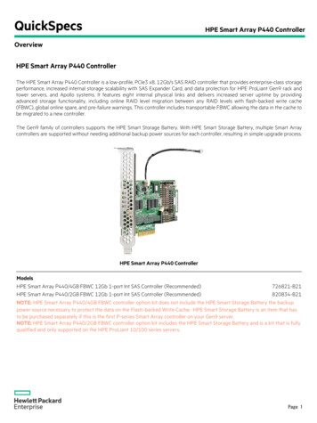
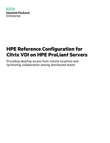
Front panel componentsItemDescription1USB 3.0 port2USB 2.0 port3Drive cage bay4PCI fan (optional)5Media bay 26Media bay 1Front panel components9
Front panel LEDs and buttonItem DescriptionStatusDefinition1Solid greenSystem onFlashing greenPerforming power-onsequenceSolid amberSystem in standbyOffNo power presentSolid greenNormalFlashing greeniLO rebootingFlashing amberSystem degradedFlashing redSystem critical21Power On/Standby button and system powerLED 1Health LED 1When the LEDs described in this table flash simultaneously, a power fault has occurred. For more information, seeFront panel LED power fault codes.Front panel LEDs and button10
Front panel LED power fault codesThe following table provides a list of power fault codes, and the subsystems that are affected. Not all power faults are used by allservers.SubsystemLED behaviorSystem board1 flashProcessor2 flashesMemory3 flashesRiser board PCIe slots4 flashesFlexibleLOM5 flashesStorage controller6 flashesSystem board PCIe slots7 flashesPower backplane8 flashesStorage backplane9 flashesPower supply10 flashesPCIe expansion cards installed in riser board11 flashesChassis12 flashesGPU card13 flashesFront panel LED power fault codes11
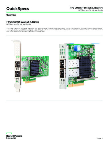
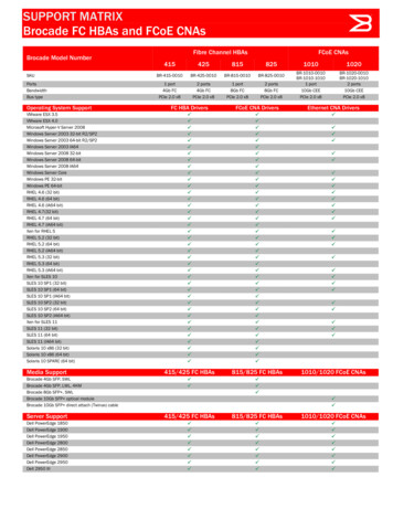
Rear panel components1ItemDescription1Flexible Slot power supply 1 (hot-plug)2Flexible Slot power supply 2 (hot-plug)3Non-hot-plug power supply4Power cord strain relief clip5NIC 1/iLO Shared Network Port6Padlock eye7System fan8Kensington security slot9NIC port 210Slot 4 PCI3 x8 (4, 1), half-length 111Slot 3 PCI3 x16 (4,1), full-length 112Slot 2 PCI3 x 8 (4,1), half-length 113Slot 1 PCI3 x16 (16, 8, 4, 1), full-length14iLO Dedicated Network Port (optional)15USB 3.0 ports16VGA port17Serial port (optional)1For more information on the expansion slot specifications, seePCI expansion slot definitions.Rear panel components12
Rear panel LEDsItemDescriptionStatusDefinition1Power supplySolid greenNormalOffSystem is off or power supply has failed.GreenNetwork linkOffNo network linkGreen or flashing greenNetwork activeOffNo network activityGreenNetwork linkOffNo network linkGreen or flashing greenNetwork activeOffNo network activity2345NIC linkNIC statusiLO linkiLO statusRear panel LEDs13
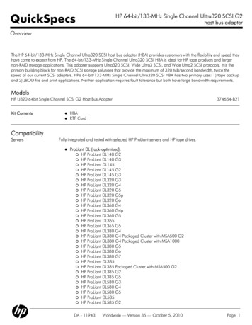
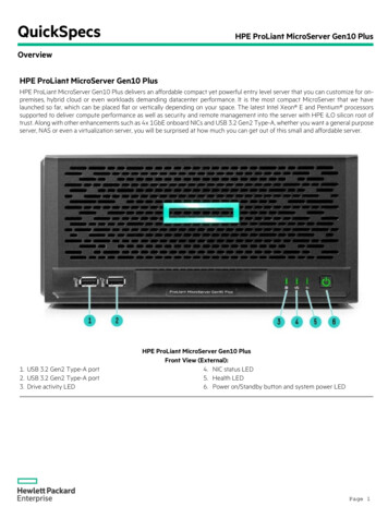
System board componentsItemDescription1System fan connector2System maintenance switch3Flexible Slot power supply connector44-pin power connector5Heatsink fan connector624-pin power connector7M.2 SSD slot8Internal USB 3.0 connector9Front I/O connector10x1 SATA port 111x1 SATA port 212Drive backplane sideband connector13PCI fan connector14x1 SATA port 315x1 SATA port 416x1 SATA port 517x1 SATA port 618Front USB connector19Controller backup power connectorsSystem board components14
1ItemDescription20Energy pack connector21TPM connector22System battery23Slot 4 PCI3 x8 (4, 1), half-length24Slot 3 PCI3 x16 (4, 1), full-length25Slot 2 PCI3 x8 (4, 1), half-length26Slot 1 PCI3 x16 (16, 8, 4, 1), full-length1111For more information on the expansion slot specifications, seePCI expansion slot definitions.System board components15
System maintenance switch descriptionsPositionDefaultFunctionS1 1OffOff iLO 5 security is enabled.On iLO 5 security is disabled.S2OffReservedS3OffReservedS4OffReservedS5 1OffOff Power-on password is enabled.On Power-on password is disabled.S6 1 , 2 , 3OffOff No functionOn Restore default manufacturing S10—ReservedS11—ReservedS12—ReservedTo access the redundant ROM, set S1, S5, and S6 to On.When the system maintenance switch position 6 is set to the On position, the system is prepared to restore all configuration settingsto their manufacturing defaults.When the system maintenance switch position 6 is set to the On position and Secure Boot is enabled, some configurations cannot berestored.For more information, see Secure Boot.System maintenance switch descriptions16
DIMM label identificationTo determine DIMM characteristics, see the label attached to the DIMM. The information in this section helps you to use the label tolocate specific information about the DIMM.ItemDescriptionExample1Capacity8 GB16 GB32 GB64 GB128 GB2Rank1R Single rank2R Dual rank4R Quad rank8R Octal rank3Data width on DRAMx4 4-bitx8 8-bitx16 16-bit4Memory generationPC4 DDR45Maximum memory speed2133 MT/s2400 MT/s2666 MT/s2933 MT/sDIMM label identification17
ItemDescriptionExample6CAS latencyP CAS 15-15-15T CAS 17-17-17U CAS 20-18-18V CAS 19-19-19 (for RDIMM, LRDIMM)V CAS 22-19-19 (for 3DS TSV LRDIMM)Y CAS 21-21-21 (for RDIMM, LRDIMM)Y CAS 24-21-21 (for 3DS TSV LRDIMM)7DIMM typeR RDIMM (registered)L LRDIMM (load reduced)E Unbuffered ECC (UDIMM)For more information about product features, specifications, options, configurations, and compatibility, see the HPE DDR4SmartMemory QuickSpecs on the Hewlett Packard Enterprise website MM label identification18
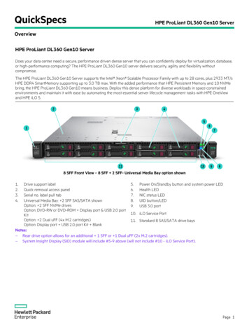
DIMM slot locationsDIMM slots are numbered sequentially (1 through 4). The supported AMP modes use the letter assignments for population guidelines.The arrow in the illustration points to the front of the server.DIMM slot locations19
PCI expansion slot definitionsSlotTypeForm factorConnector linkwidthNegotiable linkwidth1PCI3FLFH 1x1616, 8, 4, 1Supported expansion boardsSingle-width GPU10 GB Ethernet adapterType-p Smart Array controllerFC HBA2PCI3HLFH 2x84, 11 GB Ethernet adapter10 GB Ethernet adapter3PCI3FLFH 1x164, 110 GB Ethernet adapterType-p Smart Array controllerFC HBA4PCI3HLFH 2x84, 11 GB Ethernet adapter10 GB Ethernet adapter12FLFH Full length, full heightHLFH Half length, full heightPCI expansion slot definitions20
Drive LEDs and buttonsDrive LEDs and buttons21
Low-profile LFF drive LED id amberThe drive has failed.Solid blueThe drive is operating normally and being identified by a managementapplication.Flashing amber/blue(1 flash per second)The drive has failed, or a predictive failure alert has been received for thisdrive; it also has been identified by a management application.Flashing amber(1 flash per second)A predictive failure alert has been received for this drive. Replace the driveas soon as possible.2Online\Activity Solid greenThe drive is online and has no activity.Flashing green(4 flashes per second)The drive is operating normally and has activity.Flashing green(1 flash per second)The drive is doing one of the following:RebuildingPerforming a RAID migrationPerforming a strip size migrationPerforming a capacity expansionPerforming a logical drive extensionErasingSpare part activationOffThe drive is not configured by a RAID controller or a spare drive.Low-profile LFF drive LED definitions22
Smart Carrier (SC) drive LED definitionsItemLEDStatusDefinition1LocateSolid blueThe drive is being identified by a host application.Flashing blueThe drive carrier firmware is being updated or requires an update.Rotating greenDrive activityOffNo drive activitySolid whiteDo not remove the drive. Removing the drive causes one or more of the logicaldrives to fail.OffRemoving the drive does not cause a logical drive to fail.Solid greenThe drive is a member of one or more logical drives.Flashing greenThe drive is doing one of the following:Rebuilding234ActivityringDo notremoveDrivestatusPerforming a RAID migrationPerforming a strip size migrationPerforming a capacity expansionPerforming a logical drive extensionErasingSpare part activationFlashingamber/greenThe drive is a member of one or more logical drives and predicts the drive willfail.Flashing amberThe drive is not configured and predicts the drive will fail.Solid amberThe drive has failed.OffThe drive is not configured by a RAID controller or a spare drive.Smart Carrier (SC) drive LED definitions23
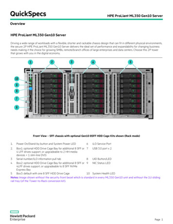
Drive bay numberingFour-bay LFF non-hot-plug drive numberingFour-bay LFF hot-plug drive numberingEight-bay SFF hot-plug drive numberingDrive bay numbering24
Drive bay numbering25
Fan numberingFan numberFan type1PCI fan (optional)2System fan3Heatsink fanFan numbering26
Fan mode behaviorThe server supports only nonredundant fan mode. If a single fan fails or is missing, the following behaviors are exhibited:The health LED flashes amber.The operating system performs a graceful shutdown.Fan mode behavior27
Media device screwsThere are eight T-15 Torx screws on the front panel. These screws are provided as spare screws for installing the USB RDX drive andSATA optical drive options.CAUTION:The media device screws on the front panel are not compatible with a SAS LTO tape drive option. To prevent damageto the drive, do not use these media device screws on a SAS LTO tape drive.Media device screws28
OperationsOperations29
Power up the serverTo power up the server, use one of the following methods:Press the Power On/Standby button.Use the virtual power button through iLO.Power up the server30
Power down the serverBefore powering down the server for any upgrade or maintenance procedures, perform a backup of critical server data and programs.IMPORTANT:When the server is in standby mode, auxiliary power is still being provided to the system.To power down the server, use one of the following methods:Press and release the Power On/Standby button.This method initiates a controlled shutdown of applications and the OS before the server enters standby mode.Press and hold the Power On/Standby button for more than 4 seconds to force the server to enter standby mode.This method forces the server to enter standby mode without properly exiting applications and the OS. If an application stopsresponding, you can use this method to force a shutdown.Use a virtual power button selection through iLO 5.This method initiates a controlled remote shutdown of applications and the OS before the server enters standby mode.Before proceeding, verify that the server is in standby mode by observing that the system power LED is amber.Power down the server31
Extend the server from the rackProcedure1. Power down the server.2. Remove all power:a. Disconnect each power cord from the power source.b. Disconnect each power cord from the server.3. Disconnect all peripheral cables from the server.WARNING:To reduce the risk of personal injury or equipment damage, be sure that the rack is adequatelystabilized before extending a component from the rack.4. Slide the server tray out of the rack:a. Loosen the server tray thumbscrews.b. Grasp the tray notch and slide the server out of the rack.Extend the server from the rack32
Remove the server from the rackWARNING: This server is heavy. To reduce the risk of personal injury or damage to theequipment:Observe local occupational health and safety requirements and guidelines for manualmaterial handling.Get help to lift and stabilize the product during installation or removal, especially when theproduct is not fastened to the rails. Hewlett Packard Enterprise recommends that aminimum of two people are required for all rack server installations. A third person may berequired to help align the server if the server is installed higher than chest level.Use caution when installing the server in or removing the server from the rack; it is unstablewhen not fastened to the rails.Procedure1. Power down the server.2. Remove all power:a. Disconnect each power cord from the power source.b. Disconnect each power cord from the server.3. Disconnect all peripheral cables from the server.4. If installed, unlock and remove the security padlock and/or the Kensington security lock.For more information, see the lock documentation.5. Extend the server from the rack .6. Remove the server from the tray.7. Place the server on a flat, level surface with the access panel facing up.Remove the server from the rack33
Slide the server into the rackProcedure1. Press and hold the blue release latches on both rails, and then slide the server tray back into the rack.2. Tighten the server tray thumbscrews.Slide the server into the rack34
Remove the front bezelProcedure1. If locked, unlock the front bezel.2. Open the front bezel.3. Pull the front bezel away from the chassis.Remove the front bezel35
Install the front bezelProcedure1. Insert the tabs on the bezel into the slots on the front chassis.2. Close the front bezel.3. Lock the front bezel.Install the front bezel36
Remove the access panelWARNING: To reduce the risk of personal injury from hot surfaces, allow the drives and theinternal system components to cool before touching them.CAUTION: To prevent damage to electrical components, take the appropriate anti-static precautions before beginningany installation, removal, or replacement procedure. Improper grounding can cause electrostatic discharge.CAUTION:Do not operate the server for long periods with the access panel open or removed. Operating the server in this mannerresults in improper airflow and improper cooling that can lead to thermal damage.Procedure1. Power down the server.2. Remove all power:a. Disconnect each power cord from the power source.b. Disconnect each power cord from the server.3. Disconnect all peripheral cables from the server.4. If installed, unlock and remove the security padlock and/or Kensington security lock.For more information, see the lock documentation.5. Do one of the following:If the server is in tower mode: Position the tower server for hardware configuration.If the server is in rack mode: Remove the server from the rack .6. Remove the front bezel .7. Remove the access panel:a. Loosen the access panel thumbscrew.b. Slide the access panel, and then lift it away from the chassis.Remove the access panel37
Install the access panelProcedure1. Install the access panel:a. Place the access panel on the chassis and slide it toward the front of the server.b. Tighten the access panel thumbscrew.2. Install the front bezel .3. Do one of the following:If the server is in tower mode: Position the tower server for operation .If the server is in rack mode: Install the server on the tray.4. If removed, install the security padlock and/or Kensington security lock.For more information, see the lock documentation.5. Connect all peripheral cables to the server.6. Connect the power cords:a. Connect each power cord to the server.b. Connect each power cord to the power source.7. Power up the server .Install the access panel38
Remove the air baffleCAUTION: For proper cooling, do not operate the server without the access panel, baffles, expansion slot covers, orblanks installed. If the server supports hot-plug components, minimize the amount of time the access panel is open.Procedure1. Power down the server.2. Remove all power:a. Disconnect each power cord from the power source.b. Disconnect each power cord from the server.3. Disconnect all peripheral cables from the server.4. Do one of the following:If the server is in tower mode: Position the tower server for hardware configuration.If the server is in rack mode: Remove the server from the rack .5. Remove the front bezel .6. Remove the access panel .7. Remove the air baffle:a. Lift the front end of the baffle from the chassis.b. Remove the baffle from the slots on the rear chassis.Remove the air baffle39
Install the air baffleCAUTION: For proper cooling, do not operate the server without the access panel, baffles, expansion slot covers, orblanks installed. If the server supports hot-plug components, minimize the amount of time the access panel is open.Procedure1. Install the air baffle:a. Insert the tabs on the baffle into the slots on the rear chassis.b. Press the front end of the baffle into the chassis.2. Install the access panel .3. Install the front bezel .4. Do one of the following:If the server is in tower mode: Position the tower server for operation .If the server is in rack mode: Install the server on the tray .5. Connect all peripheral cables to the server.6. Connect the power cords:a. Connect each power cord to the server.b. Connect each power cord to the power source.7. Power up the server .Install the air baffle40
Remove the PCI slot blank retainerProcedureRemove the PCI slot blank retainer:1. Loosen the retainer thumbscrew.2. Slide the retainer up, then remove it from the chassis.Remove the PCI slot blank retainer41
Remove the PCI slot blankCAUTION:To prevent improper cooling and thermal damage, do not operate the server unless all PCI slots have either anexpansion slot cover or an expansion board installed.Procedure1. Identify the expansion slot compatible with the option, see PCI expansion slot definitions.2. Pull up the blank opposite the selected expansion slot.Remove the PCI slot blank42
Position the tower server for hardware configurationProcedurePlace the server on a flat, level surface with the access panel facing up.Position the tower server for hardware configuration43
Position the tower server for operationProcedureReturn the server to an upright position.Position the tower server for operation44
SetupSetup45
Initial system installationDepending on your technical expertise and the complexity of the product, for the initial system installation, select one of the followingoptions:Ordering the HPE Installation ServiceSetting up the serverInitial system installation46
HPE Installation ServiceHPE Installation Service provides basic installation of Hewlett Packard Enterprise branded equipment, software products, as well asHPE-supported products from other vendors that are sold by HPE or by HPE authorized resellers. The Installation Service is part of asuite of HPE deployment services that are designed to give users the peace of mind that comes from knowing that their HPE and HPEsupported products have been installed by an HPE specialist.The HPE Installation Service provides the following benefits:Installation by an HPE authorized technical specialist.Verification prior to installation that all service prerequisites are met.Delivery of the service at a mutually scheduled time convenient to your organization.Allows your IT resources to stay focused on their core tasks and priorities.Full coverage during the warranty period for products that require installation by an HPE authorized technical specialist.For more information on the features, limitations, provisions, and ordering information of the HPE Installation Service, see this HewlettPackard Enterprise erviceHPE Installation Service47
Setting up the serverPrerequisitesBefore setting up the server:Download the latest SPP:https://www.hpe.com/servers/spp/downloadYou might be prompted for your HPE Passport credentials.Verify that your OS or virtualization software is supported:https://www.hpe.com/info/ossupportReview the UEFI Deployment Guide for HPE ProLiant Gen10 Servers and HPE nIf the UEFI requirements are not met, you might experience boot failures or other errors when installing the operating system.If needed, do one of the following to download the storage driver:Download it from the HPE Support Center website:https://www.hpe.com/support/hpescExtract it from the SPP.Read the operational requirements for the server:Operational requirementsRead the safety and compliance information on the HPE nce-enterpriseproductsIf the tower-to-rack conversion kit is used, read the rack warnings and cautions:Rack warnings and cautionsProcedureUnbox the server1. Unbox the server and verify the contents:ServerPower cordRack-mounting hardware (optional)DocumentationThe server does not ship with OS media. All system software and firmware is preloaded on the server.Install the hardware options2. (Optional) Install the hardware options. For installation instructions, see Hardware options installation.Orient the server and connect the peripherals3. Select the server orientation:If the server is in tower mode: Position the tower server for hardware configuration.If the server is in rack mode: Remove the server from the rack .4. Decide how to manage the server:Locally: Use a KVM switch or connect a keyboard, monitor, and mouse.Remotely: Connect to the iLO web interface and run a remote console:a. Verify the following:iLO is licensed to use the remote console feature.If iLO is not licensed, visit:Setting up the server48
https://www.hpe.com/info/iloThe iLO port is connected to a secure network.b. Using a browser, navigate to the iLO web interface, and then log in.https:// iLO hostname or IP address Note the following:The iLO hostname is on the serial number/iLO information pull tab.If a DHCP server assigns the IP address, the IP address appears on the boot screen.If a static IP address is assigned, use that IP address.The default login credentials are on the serial label pull tab.c. In the side navigation, click Remote Console & Media, and then launch a remote console.Power on the server5. Press the Power On/Standby button.For remote manageme
4.14.3.3 Retaining the BitLocker recovery key/password 5 Cabling 5.1 Cabling guidelines 5.2 Storage cabling 5.2.1 LFF non-hot-plug drive cabling from the media bay 5.2.2 LFF non-hot-plug drive cabling from the drive cage 5.2.3 LFF hot-plug drive cabling 5.2.4 SFF hot-plug drive cabling 5.3 Energy pack cabling 5.4 Controller backup power cabling