Transcription
This article was published in ASHRAE Journal, July 2012. Copyright 2012 ASHRAE. Posted at www.ashrae.org. This article may not becopied and/or distributed electronically or in paper form without permission of ASHRAE. For more information about ASHRAE Journal, visitwww.ashrae.org.Applying VRF?Don’t Overlook Standard 15By Stephen W. Duda, P.E., Member ASHRAEVariable refrigerant flow (VRF) systems have been used inJapan for at least two decades, and are now receiving at-tention in North America as a potential HVAC system choice in commercial, retail, institutional, hospitality, and multifamily residentialapplications. Indeed, the recently renovated ASHRAE headquartersin Atlanta includes such a system in a portion of the building. HVACsystem designers who once applied water-source heat pump loops,hydronic fan-coil networks, packaged terminal units, rooftop directexpansion units and other all-air systems, are now applying VRF.Why VRF? In many cases, VRF canbe shown to offer good seasonal energy efficiency at a reasonable first cost.VRF is mentioned in the Advanced Energy Design Guide Series,1 so there iscertainly a sustainability componentbehind the interest in VRF. But the pros18ASHRAE Journaland cons of VRF systems are beyond thescope of this article; the intent of whichis simply to remind design professionalsof the relevant refrigerant safety requirements found in Standard 15-2010. Forpeer-reviewed literature on VRF, see theApril 2007 ASHRAE Journal,2 the June2008 ASHRAE Journal,3 and the 2012ASHRAE Handbook—HVAC Systems andEquipment.4 The 2012 ASHRAE Handbook—HVAC Systems and Equipment hasa full new chapter on VRF systems.This article explores the following objectives: Why Standard 15 should not beoverlooked when applying VRF; How to find and look up the Refrigerant Concentration Limit (RCL); How to calculate refrigerant application limits; Understand what situations maycause a VRF installation to violate Standard 15; Understand and use favorable designtechniques to apply VRF within Standard 15; and Address ambiguities in Standard 15.About the AuthorStephen W. Duda, P.E., is assistant director ofmechanical engineering for Ross & Baruzzini in St.Louis. He has been a member of Standing Standards Project Committee (SSPC) 15 since 2002.a s h r a e . o r gJuly 2012
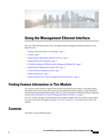
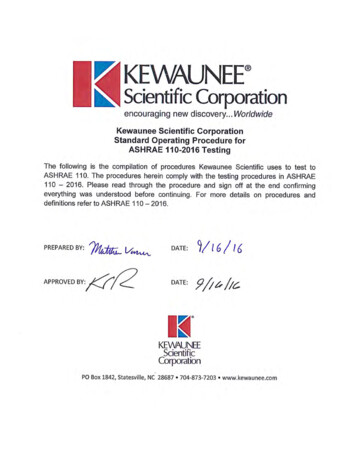
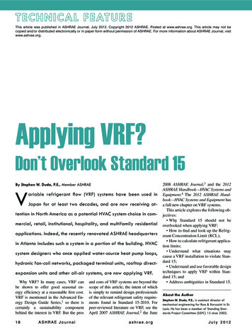
(This article is based on a published conference paper by theauthor,5 and the reader is referred to that paper for additionaltechnical detail.)Standard 15 and VRFIn part, Standard 15, Safety Standard for Refrigeration Systems,6 strives to ensure a safe system by limiting the maximum quantity of refrigerant below that which is a danger tohuman occupants if a leak occurs. Anecdotally, there is sometimes a misconception that Standard 15 applies only to largechiller plants. In fact, Standard 15 applies to any mechanicalrefrigeration system used in stationary applications (Standard15-2010 §2.2.a).The nature of a VRF system is such that multiple evaporators are served by one common condensing unit and one common network of interconnecting refrigerant piping (Figure 1).Manufacturers of VRF system components advertise that 40 ormore evaporators can be included on one piping network, withmore than 3,000 ft (914 m) of refrigerant pipe, all connected toa single condensing unit. The evaporator units may be ductless;they may be installed above a ceiling with some distributionductwork; or they may be ducted to serve two or more rooms.A traditional DX split system applied room-by-room hasone condensing unit for each evaporator, with no interconnection to other split systems, and a refrigerant leak, therefore,would discharge only that refrigerant contained in one individual split system. A water-source heat pump system usesa modest amount of refrigerant in each individual heat pumpunit, but the interconnecting piping between rooms carrieswater, not refrigerant. Because of the interconnecting refrigerant piping, a VRF system has the theoretical potential to discharge a much larger quantity of refrigerant to indoor spacesin a catastrophic leak occurrence.At first glance, one might suppose that a large direct expansion (DX) rooftop unit would have the potential to leakand disperse a large charge of refrigerant into an occupiedspace, similar to a VRF system. Of course, this is a concernwhich should be addressed via a careful application of Standard 15. On close examination, one will see that a large DXrooftop unit serves many rooms through a network of ducts.Should the evaporator in a rooftop unit open a catastrophicleak of refrigerant, the leaked refrigerant would be dispersedto multiple rooms via the ductwork, in some rough proportionto the overall room-by-room volume based on the connectedair-distribution system. A VRF system has a magnified concern because it could potentially discharge all of a comparablerefrigerant charge to one individual room.Applying Standard 15Moving further into the application of Standard 15, Section 4 requires the design professional to select an OccupancyClassification from among seven choices. In Section 5, a Re-Condensing UnitTypicalEvaporatorUnitCommonRefrigerantPiping NetworkFigure 1: Simplified variable refrigerant flow system.frigerating System Classification must be selected. A VRFsystem is classified as a Direct System (§5.1.1) for which theevaporator coils are in direct contact with the air being cooled.This is in contrast to an Indirect System; for example, a chilledwater fan-coil system in which only the water coil is in direct contact with the air being cooled. Under Standard 15, aVRF system is a High-Probability System (§5.2.1) becausethe location of components (e.g., the evaporator) is such that aleakage of refrigerant from a failed connection, seal, or component can enter the occupied space. A Direct System is also aHigh-Probability System as defined by Standard 15.Refrigerant Concentration Limit (RCL)At this point, one must refer to ANSI/ASHRAE Standard34-20107 to determine the maximum allowable refrigerantconcentration, or RCL (refrigerant concentration limit) andother pertinent safety classifications. (RCL was once foundin Standard 15 but has been moved to Standard 34 beginningwith the 2010 edition.)A common refrigerant for commercial VRF systems is R410A, and that refrigerant will be followed throughout thisarticle. Per Standard 34, Table 2, the safety classification ofR-410A is Group A1 (meaning non-flammable and non-toxic).Even though R-410A is Group A1, its ability to displace oxygenis a serious danger to occupants if released in large quantitiesinto smaller-volume spaces. Therefore, Standard 34, Table 2(through Addendum l*) has established an RCL for R-410A at26 lbs of refrigerant per 1,000 ft3 of room volume (420 g/m3).Now the Occupancy Classification becomes important. ForInstitutional Occupancies such as patient care areas of hospitals, the RCL is cut in half (§7.2.1), effectively changing theRCL for R-410A to 13 lb/1,000 ft3 (210 g/m3) in that classification.The volume of the smallest individual space(s) served byan individual evaporator unit, or the smallest individual room*ASHRAE Standard 34-2010 Addendum l recently increased this value from 25 to 26 lb/1,000 ft³ (420 g/m3). State or local codes10 that reference 34-2010 maynot include the addenda for code purposes, in which case the new value would not take effect until Standard 34-2013 edition (not yet published) is adopted bythose bodies.July 2012ASHRAE Journal19
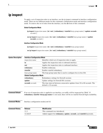
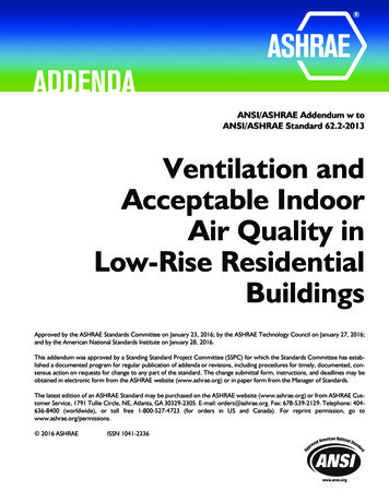
through which refrigerant piping is installed, is used to determine the maximum potential refrigerant concentration in theevent of a leak (§7.3). If that room has permanent opening(s)to adjacent room(s), the combined room volumes may be used( § 7.3.1). The space above a suspended ceiling is not considered as part of the room volume unless it is used as part of theair supply or return path ( § 7.3.2.2). Any proposed VRF system will need to respect the RCL of 26 lb/1,000 ft3 (420 g/m3),or 13 lb/1,000 ft3 (210 g/m3) if institutional, for the smallestspace(s) served by an individual evaporator unit or crossed byrefrigerant piping.The Machinery Room paragraphs (Standard 15-2010 §8.11and 8.12) are not discussed here. While Machinery Roomprovisions such as refrigerant leak detection, alarms and increased ventilation will be familiar to experienced designersof large chiller systems, Machinery Rooms are not an applicable compliance path for VRF systems. Machinery Roomsare not to be occupied by anybody other than authorizedpersonnel (§8.11.8), effectively voiding any attempt to use aMachinery Room compliance path in a VRF system servingoccupied space.Example CalculationsPublished catalog data from manufacturers show a typicalfactory refrigerant charge of 2 to 3 lb per nominal ton of capacity (0.3 to 0.4 kg/kW), with an additional 1 to 3 lb pernominal ton (0.1 to 0.4 kg/kW) contained in the field piping(subject to routing and layout), for a practical range of 3 to 6lb per ton (0.4 to 0.8 kg/kW). Operating pressures for R-410Asystems are on the order of 450 psig (3.1 MPa).9 These operating parameters of commercial VRF systems are followed bythree examples.Example 1: Commercial Office BuildingOne actual installed-and-operating VRF system the authorviewed in preparation for this article served a commercialoffice. The VRF system’s condensing unit nameplate wasstamped 478 psig (3.3 MPa) high side and 320 psig (2.2 MPa)low side; 550 psig (3.8 MPa) test pressure; 96 MBh (28 kW)capacity; 23.4 lbs (10.6 kg) factory charge of R-410A. Thenetwork features three parallel field pipes (liquid, suction, andhot gas) because the system is designed as a heat pump network, allowing some zones to be in heat mode while otherzones are in cooling mode. The total charge was 40 to 41 lb(18 to 19 kg) when field piping was included.A simplified sketch of the office layout is found in Figure2. A total of seven ductless in-room console evaporator units,one installed in each room plus the corridor, are networkedwith one condensing unit. In this example, the smallest individual room with its own evaporator is 12 ft by 8 ft (3.7 m by2.4 m), with a 9 ft (2.7 m) ceiling, for a volume of 864 ft3 (24.5m3). Therefore, the maximum allowable refrigerant charge ofR-410A is 22.4 lb (10.2 kg). Since the actual system chargeis 40 to 41 lb (18 to 19 kg), it initially appears this installationdoes not comply with Standard 15.20ASHRAE Journal10 ft15 ftSales25 ftSupportConference RoomCorridorOffice12 ftPrivate8 ft15 ft8 ftComputer Room12 ft30 ftFigure 2: Commercial office layout. Seven evaporator units,one installed within each room plus the corridor, are networkedon one common refrigerant circuit with one condensing unit.One common approach to compliance is the connectingspace clause. If the room includes permanent openings to adjacent rooms, those rooms may be combined in the volumecalculation ( § 7.3.1). The room’s door probably does not qualify as a permanent opening, because the door will be closed atleast some of the time, making the opening non-permanent. Ifone imagines this room is a human resource director’s office,for example, it should be assumed that room doors will beoccasionally closed for private conversations, and other permanent openings between rooms (such as air transfer grilles)might not be permitted for reasons of crosstalk. More on thistopic is found in the “Ambiguities” section.Finally, we must discuss the corridor itself. Refrigerant piping shall not be installed in an enclosed public stairway, stairlanding, or means of egress (§8.10.2). If the corridor shown inFigure 2 is a means of egress, one should route the piping soit does not pass through the corridor, and the evaporator unitserving the corridor should be located outside the corridor.Tips Toward ComplianceIn Example 1, we found a potential safety issue with a higher-than-allowable system charge serving a small office. Several options are available to the design professional to avoidthis situation.1. One option is to remove the smallest office from theVRF system and condition it with a separate unit, perhaps apackaged terminal air conditioner (PTAC), and route the VRFrefrigerant pipe so that it does not pass through the smallestoffice. In Example 1, the next-smallest office becomes thecritical room, at 12 ft by 12 ft (3.7 m by 3.7 m), with a 9 ft(2.7 m) ceiling, for a volume of 1,296 ft3 (36.7 m3) and maximum allowable R-410A charge of 33.7 lbs (15.3 kg). With thereduced capacity found by eliminating one evaporator unit,a s h r a e . o r gJuly 2012
Advertisement formerly in this space.
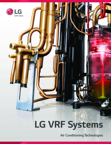
along with a re-optimized piping layout,Maximum RCL Factor forNet System Refrigerant“Critical”perhaps the total system charge will nowExampleR-410A from Std 15Concentration LimitRoom Size(ft3)(lb/1,000 ft3)(lb)be in compliance.2. Another allowable “fix” would be 1a – Commercial8642622.4to use one common ducted evaporaOffice Buildingtor to condition the two smallest rooms1b*1,2962633.7together, allowing both rooms to besummed for purpose of compliance.2 – Hotel2,5162665.43. In lieu of an in-room console unit,3 – Hospital1,7001322.1another option is to use an above-ceiling evaporator unit ducted to one or *Similar to Example 1a with the smallest room removed from the variable refrigerant flow system.more of the smaller rooms, while drawing unducted return air through the Table 1: Summary of three example calculations.ceiling cavity. Therefore, the ceilingvoid space could now be counted as part of the room volumeSince VRF evaporator units are often 100% recirculating(§7.3.2.2).types, a separate system for delivering outdoor air, such as a4. Finally, one could use two completely separate VRF sys- dedicated outdoor air system (DOAS) is often provided. Antems: one for each side of the corridor, and avoid the corridor example is a hotel room continuously ventilated with outdoorair delivered to the sleeping area and exhaust air in the bathaltogether, particularly if the corridor is a means of egress.room. Can the parallel ventilation system be relied upon fordilution of a hypothetical refrigerant leak? Formal InterpreExample 2: Hotel Guest RoomsNext, imagine a guest room floor of a hotel featuring a se- tation IC 15-2007-38 stated that increasing the allowable reries of identical units of 350 ft2 (32.5 m2) with an 8.5 ft (2.6 frigerant limits for R-410A due to dilution by supply and/orm) ceiling, for a volume of 2,975 ft3 (84.2 m3). A VRF system exhaust air ventilation should not be considered.using R-410A is proposed, with a 1 ton (3.5 kW) evaporatorper guest unit. What is the maximum refrigerant capacity per- Example 3: Hospital Patient Roomsmitted in one VRF network? The RCL is 26 lb/1,000 ft3 (420Finally, consider the application of VRF to the in-patient roomg/m3) for R-410A in a Residential occupancy. Therefore, the wing of a hospital. At first glance, this may seem to be verymaximum permissible total refrigerant charge is 77.3 lb (35.1 similar to the previous hotel room example. However, recallkg) including the condensing unit, all evaporator units, and the that for Institutional occupancies, the RCL is reduced by 50%.field refrigerant piping.A typical hospital patient room (again excluding bathroom asHowever, system designers should consider the ramifica- for the hotel) may be 200 ft2 (18.6 m2) with an 8.5 ft (2.6 m)tions of the bathroom in a typical hotel guest room. Some hotel ceiling, for a volume of 1,700 ft3 (48.1 m3). A VRF system usguests close the door of their bathroom before sleeping. With ing R-410A is proposed, with one 0.75 ton (2.6 kW) evaporathe bathroom door closed, the volume of space to which the re- tor per guest unit. Now the RCL is 13 lb/1,000 ft3 (210 g/m3)frigerant may disperse now would exclude the bathroom. For- and the maximum permissible total system refrigerant chargemal Interpretation IC 15-2007-28 implies that the bathroom of is 22.1 lb (10.0 kg). Again, assuming a refrigerant charge of 4.5a typical hotel guest room should not be counted in the room lb per ton (0.6 kg/kW), the refrigerant charge limit would allowvolume calculation. If, for example, the bathroom is 54 ft2 (5.0 a 4.9 ton (16.6 kW) system, or a maximum of 6 rooms with am2), the effective volume of the guest room proper is reduced 0.75 ton (2.6 kW) capacity requirement per room.to 2,516 ft3 (71.2 m3). In this case, the maximum permissibletotal system refrigerant charge is 65.4 lb (29.7 kg).AmbiguitiesHow many of these guest rooms can be networked on oneA key component of the previous example calculationsVRF system? For illustrative purposes only, let us assume is the determination of the volume of the smallest occupiedan R-410A refrigerant charge of 4.5 lb per ton (0.6 kg/kW). space not connected to other spaces through permanent openIn the example above, a 65.4 lb (29.7 kg) refrigerant charge ings ( § 7.3.1). If two or more rooms are connected by permalimit would allow a 14 ton (49 kW) system, or a maximum nent openings, the volume of those rooms may be combined toof 14 rooms with a 1 ton (3.5 kW) capacity requirement per find the RCL. A potential ambiguity exists in the evaluation ofguest room. So a VRF system in this hypothetical hotel would what constitutes a permanent opening. Does an undercut doormeet the RCL limit, as long as guest rooms are grouped into or a transfer opening qualify? If so, how large an undercut orseparate VRF systems of not more than 14 rooms/each. The transfer opening would be needed? These questions are notactual capacity, room size, load calculation, refrigerant type specifically addressed in Standard 15.and refrigerant charge of each system must be evaluated on aClearly, undercut doors or transfer openings would eventucase-by-case basis and may differ from this example, but these ally permit a large leak of refrigerant in one small room to disfigures lend some order-of-magnitude to the discussion.perse to adjacent rooms. However, without detailed study or22ASHRAE Journala s h r a e . o r gJuly 2012
Advertisement formerly in this space.
modeling, we do not know that this will occur quickly enoughto protect the safety of the room’s occupants. The driving forceexpelling R-410A from a ruptured refrigerant pipe may be onthe order of 450 psig (3.1 MPa) for the system high side, butthe driving force pushing transfer air under a door or through atransfer opening is five or six orders-of-magnitude less. Ceiling-mounted transfer ducts are also suspect, since most commonly used refrigerants are heavier than air. The Engineerof-Record must decide whether to rely on undercut doors ortransfer openings as a path to compliance.It is clear that some ASHRAE research would be helpfulin better defining how to treat an undercut door or a transferopening. Concurrent with publication of this article, a researchtopic acceptance request (RTAR) is being processed throughproper ASHRAE channels, proposing ASHRAE research onthis topic.Finally, this author is anecdotally aware of another approachto refrigerant leak management, one that involves the installation of automatic shutoff valves within the field refrigerant piping. In conjunction with refrigerant leak detectors, the intent isto isolate a leak to one piping segment and limit the quantityof refrigerant that can be leaked between valves to a quantitybelow the RCL. This approach is not addressed by Standard 15.The only place within Standard 15 that refrigerant leak detec-Advertisement formerly in this space.24tors are addressed is within the Machinery Room compliancepath, which is not appropriate for occupied space. Furthermore, trapping of liquid refrigerant subject to hydrostatic expansion due to closing of isolation valves must be addressed bypressure relief devices and/or engineering controls (§9.4.3.1).ConclusionsThis article intended simply to remind designers who are applying VRF that careful application of Standard 15 is necessary. Within the bounds of Standard 15, VRF systems can beproperly selected, designed, installed, and operated. It may beadvantageous to remove small rooms from a VRF system andserve those rooms separately; or use more, smaller, separateVRF system networks in lieu of one larger system, or servemultiple small rooms with one common ducted evaporator.Routing is also a key consideration, to avoid routing refrigerantpiping through smaller enclosed rooms with a lower maximumallowable charge. Operating pressures are relatively high, making the integrity of all the field joints critical, so enforce specification language requiring pressure testing of field piping.DisclaimerThe contents of this article shall not be construed as an official interpretation of Standard 15. While the author of thisarticle is a member of Standing Standards Project Committee (SSPC) 15, the information presented in the article is theview of the author alone and does not necessarily represent theviews of SSPC 15. The summary of Standard 15 in this articleis specific to VRF systems, and many portions of the standardnot specific to these systems were not discussed for reasons ofbrevity. All numerical examples provided in this article are forillustrative purposes only; every building is unique and mustbe studied with respect to Standard 15 on a case-by-case basis.Official interpretations may be requested of SSPC 15 throughthe ASHRAE website.References1. ASHRAE. 2011. Advanced Energy Design Guide for Small toMedium Office Buildings: 50% Energy Savings.2. Goetzler, W. 2007. “Variable refrigerant flow systems.” ASHRAEJournal 49(4):24.3. Afify, R. 2008. “Designing VRF systems.” ASHRAE Journal50(6):52.4. 2012 ASHRAE Handbook—Systems and Equipment, Chapter 18.5. Duda, S. 2011. “Application of ASHRAE Standard 15-2010 withrespect to multi-evaporator split air-conditioning systems.” ASHRAETransactions 117(2).6. ASHRAE Standard 15-2010, Safety Standard for RefrigerationSystems.7. ASHRAE Standard 34-2010, Designation and Safety Classification of Refrigerants.8. ASHRAE Standard 15-2007, Safety Standard for RefrigerationSystems. Interpretations IC-15-2007-2 and IC-15-2007-3 as quotedin this article were approved by vote of SSPC 15 on Jan. 30, 2011.9. 2009 ASHRAE Handbook—Fundamentals, Chapter 30.31.10. ICC. 2009. International Mechanical Code, Chapter 11. Chicago:International Code Council, Inc.A S H R A E J o u r n a lJuly 2012
mon network of interconnecting refrigerant piping (Figure 1). Manufacturers of VRF system components advertise that 40 or more evaporators can be included on one piping network, with more than 3,000 ft (914 m) of refrigerant pipe, all connected to a single condensing unit. The evaporator units may be ductless;