Transcription
ASHRAE Standards 15 and 34 –Considerations for VRV/VRF SystemsRESIDENTIAL LIGHT COMMERCIAL COMMERCIALTechnical ArticleMay 2013
ASHRAE Standards 15 and 34 –Considerations for VRV/VRF SystemsExecutive SummaryThe Variable Refrigerant Volume (VRV) technology was introduced by Daikin in the early 80’sas an alternative method of cooling and heating in commercial buildings. Today over 25 millionindividual spaces are being served by this technology. VRV is a very energy efficient andflexible equivalent to a chiller system while it also offers superior comfort compared totraditional air handler terminal units.The ASHRAE Standard 15 is significant to HVAC manufacturers, engineers and contractorsbecause it specifies compliant design, construction, installation and operation of refrigerationsystems. The standard was originally recognized in October 1930. Over time, the scope of thestandard has been expanded but the features and technology of a VRV system have not beenspecifically addressed.This document demonstrates that; VRV Systems can be properly selected and designed adhering to ASHRAE SafetyStandard 15, and Standard 34. Since Standard 15 is an application based standard, not an equipment design guide,engineering judgment can be required when applying the standard. It is recommended to use the step-by-step approach, described in this document inorder to ensure that the design of a system follows Standards 15 and 34.Published by the Daikin Product Marketing Department(Daikin’s products are subject to continuous improvements. Daikin reserves the right to modify product design, specification and information in this documentwithout notice and without incurring any obligation.)Page 2 of 17
IntroductionVRV TechnologyIn the early 1980s, the Variable Refrigerant Volume (VRV) technology was introduced byDaikin as an alternative method of cooling and heating in commercial buildings. Although VRVhas been commercially available globally for over 30 years, it remains a relatively new conceptto the North American market.VRV is an applied heating and cooling system that distributes refrigerant, rather than water, tomultiple fan coil units serving the conditioned spaces. The natural attributes of a VRV systemposition it as a modular and scalable energy-saving equivalent to a chiller system whileoffering superior comfort when compared to traditional air handler terminal units. The compact,lightweight structure within the VRV modular concept ensures ease of installation in small orlarge buildings.ASHRAE Standard 15The ASHRAE Standard 15-2010 provides safeguards for life, limb, health, property, andprescribes safety requirements.The standard is recognized by equipment manufacturers, “This standard specifies safedesign, construction, installation,engineers, and contractors as the main guide for personal safety and operation of refrigerationinvolving refrigeration systems. It strives to ensure a safe systems.”application of refrigerant systems by limiting the maximum charge “This standard appliesso that a complete discharge due to a leak into a small, occupied, a. to the design, construction, test,installation, operation, andand enclosed room can never exceed the allowable limit.inspection of mechanical andAs with most standards, ASHRAE Standard 15 is an application absorption refrigeration systems,based standard, not an equipment design guide, so substantial including heat pump systems usedengineering judgment can be required when designing a system. in stationary applications; ”ASHRAE Standards are part of the “National Voluntary Reprinted with permission.Consensus Standard”. In order for a standard to become ASHRAE, www.ashrae.org2010 ANSI/ASHRAE Standard 15mandatory, it must first become model building code by anadoption process into the International Mechanical Code (IMC). Thereafter, the model codebecomes mandatory when it is adopted at the state or local jurisdiction level. Since theconversion from ASHRAE Standard to state/local code can take time and parts of the originalstandard often changes, it is recommended to review the local code as well when designing asystem.ASHRAEStandard 15IMCCITY /STATE CodePublished by the Daikin Product Marketing Department(Daikin’s products are subject to continuous improvements. Daikin reserves the right to modify product design, specification and information in this documentwithout notice and without incurring any obligation.)Page 3 of 17
ASHRAE Standard 15 equivalent standards exist in Europe and Asia. Systems utilizing theVariable Refrigerant Volume technology are common in these regions and are appliedsuccessfully to meet these standards.ASHRAE Standards 15 and 34 applied on the VRV technologyThe ASHRAE Standard 15 was written 1919. Initially, it was a Tentative Code and it wasrecognized as Standard B9 in October 1930.“This standard provides anOriginally, the Standard was developed for safety following a unambiguous system forcatastrophic release of the content in a pressure vessel via a numbering refrigerants andsafety valve in a short time. Over time, the scope for the assigning composition-designatingStandard has been expanded to cover most refrigerants and prefixes for refrigerants. Safetyclassifications based on toxicitysystems and 1978 it was issued by ASHRAE as Standard 15.and flammability data are includedThe current version of the Standard does not address the safety along with refrigerantof any particular refrigerant. Instead, it refers to ASHRAE concentration limits for theStandard 34-2010 which identifies safety classifications and refrigerants.”Reprinted with permission.Refrigerant Concentration Limit (RCL) for refrigerants. ASHRAE, www.ashrae.org2010 ANSI/ASHRAE Standard 34Front cover of ASHRAE Standard 15-2010is reprinted with permission. ASHRAE, www.ashrae.org.2010 ANSI/ASHRAE Standard 15.Front cover of ASHRAE Standard 34-2010is reprinted with permission. ASHRAE, www.ashrae.org.2010 ANSI/ASHRAE Standard 34.Published by the Daikin Product Marketing Department(Daikin’s products are subject to continuous improvements. Daikin reserves the right to modify product design, specification and information in this documentwithout notice and without incurring any obligation.)Page 4 of 17
Daikin VRV systems use refrigerant 410A with minimal potential safety risks compared to mostother DX-type HVAC systems. The safety classification of R410A “refrigerant concentration limitin Standard 34 is group 1 (meaning non-toxic and non-flammable), (RCL): the refrigerantit has no ozone depletion potential and it meets the stringent concentration limit, in air,mandates of both the Montreal Protocol and the U.S. determined in accordance with thisEnvironmental Protection Agency. However, due to the ability to standard and intended to reducethe risks of acute toxicity,displace oxygen, Addendum L to ASHRAE Standard 34-2010 asphyxiation, and flammabilityhas established the maximum RCL to 26 lbs/1000 ft3 of room hazards in normally occupied,enclosed spaces.”volume for occupied spaces.For Institutional Occupancies, the limit is reduced to 50% (13 Reprinted with permission. ASHRAE, www.ashrae.orglbs/1000 ft3).2010 ANSI/ASHRAE Standard 34For smaller systems with less than 6.6 lbs of total refrigerant charge, the 26 lbs/1000 ft³ limitdescribed above does not apply, regardless of refrigerant safety “Listed equipment containing notclassification, if the system is installed according to the listing and more than 6.6 lb(3 kg) ofrefrigerant, regardless of itsmanufacturer’s instructions.Since the indoor unit fan coils are in direct contact with the airbeing distributed, a VRV system is classified as a Direct Systemaccording to Standard 15.By definition, a Direct System is also classified as a HighProbability system, meaning that a leak of refrigerant canpotentially enter into occupied space.The information in this document is intended to provide guidanceto specifying and designing a VRV system while applyingASHRAE safety Standard 15. However, since many of theattributes of a modern cooling/heating technology, such as VRV,are not specifically addressed in Standard 15, there might bevariations in how the “authority having jurisdiction” (AHJ)interprets compliance requirements to Standard 15 betweenjurisdictions.Therefore, it is good practice to review the local code and workwith the local AHJ when designing a system.refrigerant safety classification, isexempt from Section 7.2 providedthe equipment is installed inaccordance with the listing andwith the manufacturer’sinstallation instructions.”Reprinted with permission. ASHRAE, www.ashrae.org2010 ANSI/ASHRAE Standard 15“A high-probability system is anysystem in which the basic design,or the location of components, issuch that a leakage of refrigerantfrom a failed connection, seal, orcomponent will enter the occupiedspace ”Reprinted with permission. ASHRAE, www.ashrae.org2010 ANSI/ASHRAE Standard 15“The terms “authority havingjurisdiction (AHJ)” and“jurisdictional authority” usedherein refer to the organization orindividual responsible forenforcing the requirements of thisstandard.”Reprinted with permission. ASHRAE, www.ashrae.org2010 ANSI/ASHRAE Standard 15Published by the Daikin Product Marketing Department(Daikin’s products are subject to continuous improvements. Daikin reserves the right to modify product design, specification and information in this documentwithout notice and without incurring any obligation.)Page 5 of 17
Applying Standard 15 when designing a VRV systemIf refrigerant system piping, components and units are located in occupied spaces, the spacesmust be evaluated regarding safety for the occupants. Occupied“occupied space: that portion ofspace is not necessarily just one room or an area but can also be the premises accessible to orseveral rooms/areas that are “connected” by corridors, ductwork occupied by people, excludingmachinery rooms.”or other means.Reprinted with permission. ASHRAE, www.ashrae.org2010 ANSI/ASHRAE Standard 15It is recommended to apply the Standard 15 requirements on thedesign of a VRV system in 4 basic steps as listed below. Thechecklist at the end of this document can be used to facilitate the steps.First StepPreliminary layout of the systemSecond StepDetermine the amount of refrigerantThird StepVerify that the VRV system layout complieswith Standard 15 requirementsFourth StepActions if a room is too small.First StepPreliminary layout of the systemThe first step in applying Standard 15 in the design process of the VRV system is to develop apreliminary layout of the complete system (piping, indoor unit fan coil units, and outdoor units)to meet the heating/cooling requirements in the rooms/zones of the project.Even though the VRV technology allows very long piping distances, due to cost and refrigerantcharge limitations in ASHRAE Standard 15, the equipment layout should strive to minimize thepiping lengths where possible.Published by the Daikin Product Marketing Department(Daikin’s products are subject to continuous improvements. Daikin reserves the right to modify product design, specification and information in this documentwithout notice and without incurring any obligation.)Page 6 of 17
Second StepDetermine the amount of refrigerantThe second step is to determine the total amount of refrigerant 410A for the system.This calculation can either be done manually according to guidelines in Daikin VRV InstallationManual or by using Daikin VRV Xpress selection software. In addition to quickly providing therefrigerant charge, the output from VRV Xpress also automatically generates piping and wiringdiagrams. If piping or indoor unit fan coil locations need to be revised, the VRV Xpress willrecalculate pipe sizes and refrigerant charge automatically.If a room has more than one VRV system serving it thus more than one refrigerant circuitinstalled, it is recommended to check with the AHJ regarding how to determine the “Quantity ofRefrigerant per Occupied Space”. It is not necessarily the sum of the refrigerant charges in allof the circuits in the room. It might be allowed to use the quantity of refrigerant in the largestcircuit in the calculations.Third StepVerify that the VRV system layout complieswith Standard 15 requirementsThe third step is to verify that the initial layout of the VRV system complies with the Standard15 requirements by: Determine the occupancy classification for the room(s)Determine room volume(s)Verify that no room is too smallReview refrigerant piping requirementsThe checklist at the end of this document can be used to facilitate the steps.Determine the occupancy classification for the room(s).The classifications are: Institutional occupancy, Public assembly occupancy, Residentialoccupancy, Commercial occupancy, Large mercantile occupancy, “Institutional occupancy is aIndustrial occupancy, and Mixed occupancy.premise or that portion of aFor Institutional occupancies (a premise where the occupantscannot readily leave without assistance of others), the maximumrefrigerant concentration limit (RCL) is reduced by 50% comparedto the other occupancy classifications.For Industrial occupancies and Refrigerated rooms, severalspecial conditions applies, see section 7.2.2 in Standard 15.premise from which, because theyare disabled, debilitated, orconfined, occupants cannot readilyleave without the assistance ofothers. Institutional occupanciesinclude, among others, hospitals,nursing homes, asylums, andspaces containing locked cells.”Reprinted with permission. ASHRAE, www.ashrae.org2010 ANSI/ASHRAE Standard 15Published by the Daikin Product Marketing Department(Daikin’s products are subject to continuous improvements. Daikin reserves the right to modify product design, specification and information in this documentwithout notice and without incurring any obligation.)Page 7 of 17
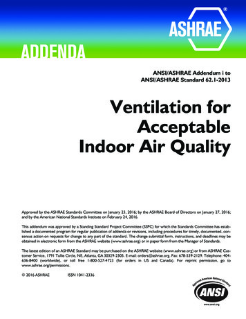
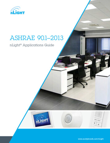
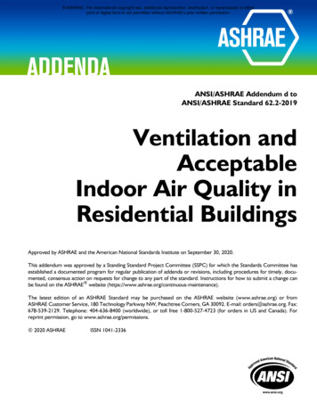
Determine Room volume(s)Calculate the room volume of the smallest occupied room(s).In addition to the rooms where each indoor unit fan coil is located, all rooms that have any partof the refrigerant piping circuit installed should be examined, as shown in the following figure.According to Standard 15, volume calculation shall be basedon the volume of space to which the refrigerant disperses incase of a leak. This is an important section in Standard 15 and itshould be considered if other parts of the Standard do not giveclear enough directions when applying the Standard.The plenum space above a suspended ceiling can be considereda part of the room if it is a part of the air supply or return system.When calculating the room volume, it is permissible to include theair volume of the supply/return ducts connected to fan coil if theairflow cannot be shut-off (excludes fire and smoke dampers, andVAV units if the units cannot shut down to less than 10 % ofdesign airflow, with the fan running).“Volume Calculations. The volume shall be based on the volume ofspace to which refrigerantdisperses in the event of arefrigerant leak.”Reprinted with permission. ASHRAE, www.ashrae.org2010 ANSI/ASHRAE Standard 15“Plenums. The space above asuspended ceilingshall not be included in calculatingthe refrigerant quantity limit in thesystem unless such space is part ofthe air supply or return system.”Reprinted with permission. ASHRAE, www.ashrae.org2010 ANSI/ASHRAE Standard 15“Supply and Return Ducts. Thevolume of the supply and returnducts and plenums shall beincluded when calculating therefrigerant quantity limit in thesystem.”Reprinted with permission. ASHRAE, www.ashrae.org2010 ANSI/ASHRAE Standard 15Published by the Daikin Product Marketing Department(Daikin’s products are subject to continuous improvements. Daikin reserves the right to modify product design, specification and information in this documentwithout notice and without incurring any obligation.)Page 8 of 17
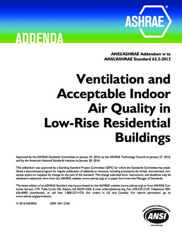
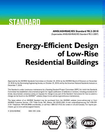
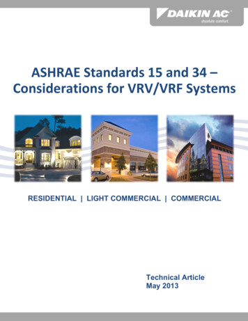
Verify that no room is too smallUsing the calculated total refrigerant charge, verify that there are no rooms that have a part ofthe refrigeration circuit installed, that has a smaller calculated room size than shown in thefollowing Diagram.If a room is verified to be too small according to the Diagram, review the section “Fourth Step– Actions if a room is too small” in this document.Example:According to Standard 15, minimum allowed floor area is 200 ft2 if the ceiling height is 10 ft for a noninstitutional occupancy space that has part of a 52 lbs R410A charge piping circuit installed.Formula used for the DiagramPublished by the Daikin Product Marketing Department(Daikin’s products are subject to continuous improvements. Daikin reserves the right to modify product design, specification and information in this documentwithout notice and without incurring any obligation.)Page 9 of 17
Review refrigerant piping requirementsRefrigerant piping locationAccording to Standard 15, Refrigerant Piping must not be less than 7.25ft (2.2m) above thefloor unless the piping is located against the ceiling and is “Refrigerant piping crossing an openpermitted by the AHJ.space that affords passageway in anyRefrigerant piping cannot be placed in a shaft containing amoving object and must not be installed in an enclosed publicmeans of egress.The wording of the paragraph in Standard 15 says that pipingcannot be installed in enclosed stairway/landing or means ofegress. However, it also implies that the AHJ could approveinstallation of the piping above the ceiling as the statement is toprotect the piping from being damaged or cause obstruction to anoccupant trying to exit the building.Standard 15 also states that field installed refrigerant pipe jointsmust remain exposed for visual inspection before they arecovered or enclosed.In addition, refrigerant piping must be properly supported and if itis installed in concrete floors the piping must be encased in pipeduct.Refrigerant monitoringStandard 15 only mentions refrigerant monitoring and alarmfunctions in case of a leak for refrigerating machinery rooms. Foroccupied spaces, refrigerant monitoring should be discussed withthe local AHJ.building shall not be less than 7.25ft(2.2m) above the floor unless pipingis located against the ceiling of suchspace and is permitted by the AHJ”.Reprinted with permission. ASHRAE, www.ashrae.org2010 ANSI/ASHRAE Standard 15“Passages shall not be obstructed byrefrigerant piping. Refrigerant pipingshall not be placed in any elevator,dumbwaiter, or other shaftcontaining a moving object or in anyshaft that has openings to livingquarters or to means of egress.Refrigerant piping shall not beinstalled in an enclosed publicstairway, stair landing, or means ofegress.”Reprinted with permission. ASHRAE, www.ashrae.org2010 ANSI/ASHRAE Standard 15“Refrigerant Pipe Joint Inspection.Refrigerant pipe joints erected on thepremises shall be exposed to view forvisual inspection prior to beingcovered or enclosed.”“Refrigerant piping installed inconcrete floors shall be encased inpipe duct. Refrigerant piping shall beproperly isolated and supported toprevent damaging vibration, stress,or corrosion.”Reprinted with permission. ASHRAE, www.ashrae.org2010 ANSI/ASHRAE Standard 15Published by the Daikin Product Marketing Department(Daikin’s products are subject to continuous improvements. Daikin reserves the right to modify product design, specification and information in this documentwithout notice and without incurring any obligation.)Page 10 of 17
Roof and floor piping penetrationA VRV system is classified as a direct system and it must always be designed according to theleakage concentration limits in ASHRAE Standard 34. Therefore,“Refrigerant piping shall notthe penetration restriction in Section 8.10.3 in Standard 15 does penetrate floors, ceiling, or roofs.”not apply for VRV if the system is designed correctly and the “Exceptions d. Penetrations of a direct systemRCL is within the stated limits.Also, if the RCL is above the stated limits in a non-industrial where refrigerant concentrationoccupancy application, the penetration restriction does not apply does not exceed that listed in Table1 or 2 of ASHRAE Standard 34 forif:the smallest occupied space piping is enclosed by an approved duct/shaft with through which the refrigerantpiping passes.”openings to the floors served by the systemReprinted with permission.or ASHRAE, www.ashrae.org piping is located on the exterior wall of a building when2010 ANSI/ASHRAE Standard 15vented to the outdoors or to the space served by the systemand not used as an air shaft, or similar space.Fourth StepActions if a room is too smallIf the calculated room volume is too small in relation to the actual refrigerant charge in thesystem, there are generally three different ways to remedy this situation: Increase the room volume used in calculationsRelocate/remove piping or indoor unit fan coilReduce the refrigerant charge by dividing the refrigerant circuit into multiplesmaller systemsThe checklist at the end of this document can be used to facilitate the possible actions.Increase the room volume used in calculationsPermanent openingsIf a room is too small for the amount of refrigerant, it might be possible to increase the roomvolume used in the calculations by “connecting” it to other rooms “Nonconnecting Spaces. Where arefrigerating system or a partby using louvers, transfer grilles, door undercuts, or similar.A permanent opening made to increase the room volume allows thereof is located in one or moreany leak of refrigerant to disperse into the adjacent area(s). enclosed occupied spaces that donot connect through permanentHowever, since Standard 15 does not address how to calculate a openings or HVAC ducts, thepermanent opening, this should be determined by the Engineer of volume of the smallest occupiedspace shall be used to determinerecord and/or the AHJ.the refrigerant quantity limit in theThe Japanese standard JRA GL-13:2012 could serve as asystem.”guideline regarding the opening. It defines a permanent openingReprinted with permission.as one that has an area of 0.15% or more of the total floor area of ASHRAE, www.ashrae.orgthe smaller enclosed occupied space in which refrigerant2010 ANSI/ASHRAE Standard 15containing parts are located.Published by the Daikin Product Marketing Department(Daikin’s products are subject to continuous improvements. Daikin reserves the right to modify product design, specification and information in this documentwithout notice and without incurring any obligation.)Page 11 of 17
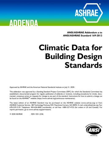
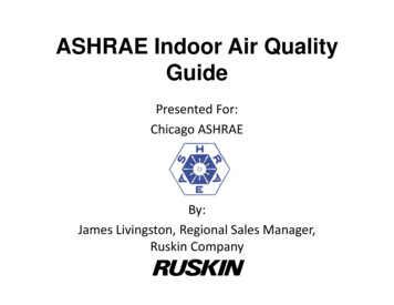
VentilationWhen occupied space is served by a mechanical ventilation system, the entire air distributionsystem must be analyzed to determine the worst-case distribution ”Ventilated Spaces. Where aof leaked refrigerant.refrigerating system or a partAccording to the formal interpretation IC 15-2007, never consider thereof is located within an airincreasing the allowable refrigerant limits due to dilution by supply handler, in an air distribution ductsystem, or in an occupied spaceand/or exhaust air ventilation.served by a mechanical ventilationDoorsA regular door that cannot be closed between two rooms shouldsatisfy the requirement of enabling connected spaces. Removingthe door completely is the safest way to make sure that therooms always are connected.system, the entire air distributionsystem shall be analyzed todetermine the worst-casedistribution of leaked refrigerant.”Reprinted with permission. ASHRAE, www.ashrae.org2010 ANSI/ASHRAE Standard 15Remove, or raise, suspended ceilingSince Standard 15 does allow the space above a suspended ceiling to be used in calculatingthe room volume if it is a part of the air supply or return system, one option could be to removethe ceiling completely. Alternatively, the suspended ceiling could possibly be raised to a heightthat provides the required room volume. This can be accommodated by using Daikin’s indoorunit fan coils that are low profile. The height of some of the ceiling units is less than 10” andthe height of a slim duct concealed unit is less than 8”.Relocate/remove piping or indoor unit fan coilRelocate the indoor unit fan coil and duct it to several roomsIf none of the actions above are possible for increasing room volume, an alternative could beto install the indoor unit fan coil outside the room that is too small. By ducting the supply air toseveral rooms, the rooms would be considered connected according to Standard 15. If a leakoccurs in the indoor unit fan coil, the refrigerant would be dispersed to both rooms, as shown inthe following figure.Published by the Daikin Product Marketing Department(Daikin’s products are subject to continuous improvements. Daikin reserves the right to modify product design, specification and information in this documentwithout notice and without incurring any obligation.)Page 12 of 17
Locate the indoor unit fan coil to the plenum above the suspended ceilingOne way to be able to include the plenum space above the “Plenums. The space above asuspended ceiling in the room volume calculation is to install an suspended ceiling shall not beindoor unit fan coil above the suspended ceiling and duct it to included in calculating theone or several smaller rooms, while drawing un-ducted return air refrigerant quantity limit in thethrough the plenum space above the suspended ceiling. See the system unless such space is part ofthe air supply or return system.”following figure.Reprinted with permission. ASHRAE, www.ashrae.org2010 ANSI/ASHRAE Standard 15Remove indoor unit fan coil from systemIf none of the prescribed actions to increase the room volume can be accomplished, oneoption could be to remove the indoor unit fan coil from the system and install a separate splitunit to handle the load in the room. Removing the unit from the system would also lower thetotal refrigerant charge in the VRV system.Optimize the piping layoutAn alternative or additional remedy is to review the piping layout to see if it can be altered toreduce refrigerant and piping.Published by the Daikin Product Marketing Department(Daikin’s products are subject to continuous improvements. Daikin reserves the right to modify product design, specification and information in this documentwithout notice and without incurring any obligation.)Page 13 of 17
Reduced lengths of the main distribution piping can decrease the refrigerant charge in thecircuit considerably. In the following figures, the Revised Piping Layout lowers the totalrefrigerant charge in the circuit to 83% of the charge for the Initial Piping Layout.Published by the Daikin Product Marketing Department(Daikin’s products are subject to continuous improvements. Daikin reserves the right to modify product design, specification and information in this documentwithout notice and without incurring any obligation.)Page 14 of 17
Reduce the refrigerant charge by dividing the refrigerant circuit into multiple smallersystemsDepending on system layout, size, and other factors, another option could be to divide thesystem into multiple smaller and completely separate VRV systems. This would dramaticallydecrease the refrigerant charge in a single circuit and due to the modularity of the VRVtechnology, the cost per Ton of cooling/heating is very similar for several smaller systems orone larger system.In the following figure, Divided System, the larger of the two refrigerant circuits contain 40% ofthe total refrigerant charge compared to the previous figures Initial Piping Layout and 48%compared to the Revised Piping Layout.Published by the Daikin Product Marketing Department(Daikin’s products are subject to continuous improvements. Daikin reserves the right to modify product design, specification and information in this documentwithout notice and without incurring any obligation.)Page 15 of 17
Additional InformationASHRAE has published a Standard 15-2001 Users Manual (ISBN 1931862168) that “wasdeveloped as a companion document to ASHRAE Standard 15-2001. It does not reflect theaddenda and changes incorporated into Standard 15-2004. The User's Manual clarifies theintent of the Standard and provides an explanation of the rationale behind it. It eases use ofthe standard by including illustrations and examples of accepted industry practice, as well asexplanations of and supporting references for formulas in the Standard. This guide also coversbuilding, system, and refrigerant classifications, restrictions on refrigerant use, installationrestrictions, and equipment and system design and construction. The User's Manual includesinformation on mechanical and absorption refrigeration systems for commercial, residential,and industrial applications.”ConclusionA VRV System can be properly selected and designed adhering to ASHRAE Safety Standards15 and 34. However, it is important to keep the following considerations in mind: Standard 15 is an application based standard, not an equipment design guide, sosubstantial engineering judgment can be required when applying the standard. Since the indoor unit fan coils are in direct contact with the air being distributed, a VRVsystem is classified as a Direct System according to Standard 15. By definition, a DirectSystem is also classified as a High Probability system, meaning that a leak of refrigerantcan potentially enter into occupied space. ASHRAE Standard 34-2010 has established the maximum Refrigerant ConcentrationLimit (RCL) for R410A to 26 lbs/1000 ft3 of room volume for occupied spaces. ForInstitutional Occupancies, the limit is 13 lbs.1000/ft3. According to Standard 15, room volume calculation “shall be based on the volume ofspace to which the refrigerant disperses in case of a leak.” Many of the attributes of a modern cooling/heating technology, such as VRV, are notaddressed in Standard 15. Therefore, it is recommended to follow a step-by-stepapproach and also work with the local “authority having jurisdiction” (AHJ) whendesigning a system.Published by the Daikin Product Marketing Department(Daikin’s products are subject to continuous improve
Published by the Daikin Product Marketing Department (Daikin's products are subject to continuous improvements. Daikin reserves the right to modify product design, specification and information in this document without notice and without incurring any obligation.) Page 2 of 17 ASHRAE Standards 15 and 34 - Considerations for VRV/VRF Systems