Transcription
Introduction to MPLSTechnologiesSantanu Dasgupta 2006 Cisco Systems, Inc. All rights reserved.1
Why MPLS? 2006 Cisco Systems, Inc. All rights reserved.2
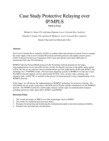
What Is MPLS? Multi Protocol Label Switching is a technology fordelivery of IP services MPLS technology switches packets (IP packets, AAL5frames) instead of routing packets to transport the data MPLS packets can run on other Layer 2 technologiessuch as ATM, FR, PPP, POS, Ethernet Other Layer 2 technologies can be run over anMPLS network 2006 Cisco Systems, Inc. All rights reserved.3
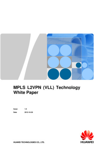
Evolution of MPLS It has evolved a long way from the original goalTDP Labels imp/dis/swapBGP MPLS VPNs (RFC 2547) From tag switchingVRF Static LabelsTE IS-IS ExtensionsTE RSVP IntegrityLDP Label ImpositionPE-CE – RIP, OSPF, STATIC, eBGP, ISISInt. Peering for CSC & I-AS Load balancingTE OSPF ExtensionsTE RSVP Refresh ReductionLDP Label SwappingMPLS VPNs – Carrier Supporting CarrierBGP VPN over IP (Biscuit)TE RSVP ExtensionsTE RSVP Reliable Messages Proposed in IETF—later combined with other proposals from IBM (ARIS),Toshiba (CSR)LDP Label DispositionMPLS VPNs – Inter-ASEIGRP – Limit #sredistributed routesTE Autoroute CalculationTE RSVP Message AuthenticationLDP inbound label filtersVPN IDVRF Aware HSRPTE Node Exclusion List SupportTE RSVP Hello State timeoutVRF Aware Static LabelsMPLS VPNs – BGP Label Distribution (RFC3107)VRF Aware GLBPTE AutoBandwidthTE MIBStatic Label (LDP)MPLS VPNs – BGP LABEL for InterAS & CSCVRF Aware VRRPTE AutoBandwidthVPN MIBVRF Aware DHCP RelayTE InterArea TE SupportMPLS LSR MIBMPLS GroupLDP Auto-enableVRF LiteFormallyCharteredLDP Session ProtectionPE-CE – EIGRPby IETFLDP-IGP SyncVRF SelectStatic Cross ConnectOSPF Sham LinkLDP Graceful RestartCiscoCalls aLDP inbound label filtersBOFVRFatIETFtoAwareStatic LabelsStatic Label (LDP)StandardizeMD5TagMPLSSwitchingiBGP & eiBGP MultipathCisco ShipsiBGP Multipath for CSC & Inter-ASMPLS(TagMultihop-eBGP supportfor Inter-ASRT-rewriteat ASBRSwitching)Large ScaleMPLS VPNVRF Aware NATTE Forwarding AdjacencySupportDeploymentDeployedVRF Aware ODAPTE Overload Avoidance SupportAToMCisco ShipsIPv6 Support with MPLS VPNs (6PE)TE Configurable Tunnel Path CalculationMPLS TEVRF Aware AAATE over ATM PVC ModeVRF Aware IS-ISTE over ATM LC-ATM modeMPLS TE SNMP NotificationTE FRR MIBTE MIBVPN MIBLayer MPLS2 LSR MIB InterproviderMPLS TE SNMP NotificationInterworking CapabilitiesVRF Fall BackVRF Aware TACACSTETE Verbatim SupportDeployedTE AutoTunnel Mesh groups -ACLsMPLS MD5 Global/GroupConfigHalf-duplex VRFsVRF Aware FirewallsTE AutoTunnel Mesh Group-OSPFLSP Ping/Traceroute V9EXP NULL Support with BGPVRF Aware IPSecTE Link ProtectionIP SLA Support for LSP Ping/Traceroute v9 LDP FECs3 label loadbalance fixVRF Aware BootpTE Node ProtectionUCPCSC/IAS Multipath Interface PeeringMulticast VPNs-IntranetPath ProtectionO-UNIOSPF Process Limit removalVRF aware Dialer WatchSRLG-ISISO-TePE Overload ProtectionVRF specific static ARPSRLG-OSPF199619971998BGP Support for EIGRP PE-CEVRF Aware TFTPVRF Aware Syslog19992000Static Route for VRFSOO for EIGRPVRF aware SNMP2547 over IP (L2TPv3)VRF aware IP SLA 2006 Cisco Systems, Inc. All rights reserved.TimeTE LSP Attributes2001Inter-AS TETE FRR MIBVRF aware Ping/TracerouteBandwidthVCCV verifications MPLS OAMProtectionEthernet OAM2002Static, Policy and Autoroute mapping20032004 AToM/CBTS/QoS based routing on to TE4
Evolution of MPLS Has been continuously evolvingTDP Labels imp/dis/swapBGP MPLS VPNs (RFC 2547)VRF Static LabelsTE IS-IS ExtensionsTE RSVP Integrity Multiple working groups at IETF are still focusing on more advancementsLDP Label ImpositionPE-CE – RIP, OSPF, STATIC, eBGP, ISISInt. Peering for CSC & I-AS Load balancingTE OSPF ExtensionsTE RSVP Refresh ReductionLDP Label SwappingMPLS VPNs – Carrier Supporting CarrierBGP VPN over IP (Biscuit)TE RSVP ExtensionsTE RSVP Reliable MessagesLDP Label DispositionMPLS VPNs – Inter-ASEIGRP – Limit #sredistributed routesTE Autoroute CalculationTE RSVP Message AuthenticationLDP inbound label filtersVPN IDVRF Aware HSRPTE Node Exclusion List SupportTE RSVP Hello State timeoutVRF Aware Static LabelsMPLS VPNs – BGP Label Distribution (RFC3107)VRF Aware GLBPTE AutoBandwidthTE MIBStatic Label (LDP)MPLS VPNs – BGP LABEL for InterAS & CSCVRF Aware VRRPTE AutoBandwidthVPN MIBStatic Cross ConnectOSPF Sham Link Huge deployment across the worldLDP Auto-enableLiteArrivalVRFofBFDMPLS LSR MIBMore advancedTE Forwarding Adjacency SupportMPLS TE SNMP NotificationPW concepts TE FRR MIBTE Overload Avoidance SupportTDM PWVRF Aware NATMobileVRFBackhaulAware ODAPVRF Aware DHCP RelayTE InterArea TE SupportLDP Session ProtectionPE-CE – EIGRPLDP-IGP SyncVRF SelectIPv6 Support with MPLS VPNs (6PE)LDP Graceful RestartiBGP & eiBGP MultipathVRF Aware AAAVPLS& HLDP inbound label filtersVPLSEvolvedVRF AwareStatic Labels(L2 StaticMPLabel (LDP)MPLS MD5Service)PathiBGP Multipath for CSC & Inter-ASComputationMultihop-eBGP support for Inter-ASRT-rewriteat ASBRElementGMPLS TE Configurable Tunnel Path CalculationVRF Aware IS-ISVRF Aware TFTPVRF Aware SyslogTE MIBMPLSP2MP Traffic TransportAdvancedTE LSP AttributesMPLS TE SNMP NotificationEngineeringProfileMPLSTE Verbatim SupportTE FRR MIB(MPLS-TP)& LabelTE AutoTunnel Mesh groups -ACLsVRF aware Ping/TracerouteOAMSwitchedTE AutoTunnel Mesh Group-OSPFVCCV verificationsMulticastTE over ATM PVC ModeVPN MIBTE over ATM LC-ATM modeMPLS LSR MIBTE Link ProtectionEthernet OAMVRF Fall BackVRF Aware TACACSMPLS MD5 Global/GroupConfigHalf-duplex VRFsVRF Aware FirewallsLSP Ping/Traceroute V9EXP NULL Support with BGPVRF Aware IPSecIP SLA Support for LSP Ping/Traceroute v9 LDP FECs3 label loadbalance fixVRF Aware BootpTE Node ProtectionUCPCSC/IAS Multipath Interface PeeringMulticast VPNs-IntranetPath ProtectionO-UNIOSPF Process Limit removalVRF aware Dialer WatchSRLG-ISISO-TePE Overload ProtectionVRF specific static ARPSRLG-OSPFBGP Support for EIGRP PE-CEStatic Route for VRFInter-AS TESOO for EIGRPVRF aware SNMPStatic, Policy and Autoroute mapping2547 over IP (L2TPv3)VRF aware IP SLA 2006 Cisco Systems, Inc. All rights reserved.2005-2010TimeAToM/CBTS/QoS based routing on to TE5
MPLS as a Foundation forValue-Added P ATMIP OpticalGMPLSAnyTransportover MPLSMPLSNetwork Infrastructure 2006 Cisco Systems, Inc. All rights reserved.6
Technology Basics 2006 Cisco Systems, Inc. All rights reserved.7
MPLS ComponentsFew Components Play Role in Creating MPLS Network: IGP: Core Routing Protocol MPLS Label Encapsulation of MPLS label Forwarding Equivalence Class Label Distribution Protocol MPLS Applications related protocols: MP-BGP, RSVP etc. 2006 Cisco Systems, Inc. All rights reserved.8
MPLS Network OverviewMPLS Core and Edge, Remote Customer Sites2. In the Core:Label swapping or switchingForward using labels (not IPaddr). Label indicates serviceclass and destination1. At Ingress Edge:Label impositionClassify & LabelpacketsPEPPEPLabel dispositionRemove labels and forwardpacketsEdge Label SwitchRouter OR(ATM Switch/ Router)Provider Edge- PEPEPECustomerA3. At Egress Edge:CustomerBLabel Switch Router (LSR)or P (Provider) routerRouter OR ATM switch label switch controller01230 1 2 3 4 5 6 7 8 9 0 1 2 3 4 5 6 7 8 9 0 1 2 3 4 5 6 7 8 9 0 1Label – 20bitsCOS STTL-8bitsCOS/EXP Class of Service: 3 Bits; S Bottom of Stack; TTL Time to Live 2006 Cisco Systems, Inc. All rights reserved.9
MPLS ComponentsEncapsulationsPPP Header(Packet over SONET/SDH)PPP HeaderLabelLayer 2/L3 PacketOne or More Labels Appended to the PacketLAN MAC Label HeaderATM MPLS Cell HeaderMAC HeaderGFC VPILabelVCILayer 2/L3 PacketPTICLPHEC DATALabel 2006 Cisco Systems, Inc. All rights reserved.10
MPLS ComponentsForwarding Equivalence ClassFEC Is Used by Label Switching Routers to Determine HowPackets Are Mapped to Label Switching Paths (LSP): IP prefix/host address Layer 2 circuits (ATM, FR, PPP, HDLC, Ethernet) Groups of addresses/sites—VPN x A bridge/switch instance—VSI Tunnel interface—traffic engineering 2006 Cisco Systems, Inc. All rights reserved.11
Label Distribution inMPLS Networks 2006 Cisco Systems, Inc. All rights reserved.12
MPLS Operation Overview1a. Existing Routing Protocols (e.g. OSPF, IS-IS)Establish Reachability to Destination Networks1b. Label Distribution Protocol (LDP)Establishes Label to DestinationNetwork Mappings2. Ingress Edge LSR Receives Packet,Performs Layer 3 Value-AddedServices, and “Labels” Packets 2006 Cisco Systems, Inc. All rights reserved.4. Edge LSR atEgress RemovesLabel and DeliversPacketTo Enable mpls:ip cefmpls label protocol ldp!Interface ether0/0mpls ip3. LSR Switches PacketsUsing Label Swapping13
Label Advertisement Modes Downstream unsolicited Downstream node just advertises labels for prefixes/FECreachable via that device Downstream on-demand Upstream node requests a label for a learnt prefix via thedownstream node Next example—ATM MPLS 2006 Cisco Systems, Inc. All rights reserved.14
IP Packet Forwarding ressPrefixI/F128.891128.890171.69171.691171.691 4Data128.89.25.4Packets ForwardedBased on IP Address 2006 Cisco Systems, Inc. All rights reserved.Data171.6915
MPLS with Downstream Unsolicited ModeStep I: Core Routing ConvergenceInAddressLabel PrefixOut OutI’face LabelInAddressLabel PrefixOut OutI’face Label128.891128.890171.691171.691 InAddressLabel PrefixOut OutI’face Label128.890 001You Can Reach 128.89 and171.69 Thru MeRouting Updates(OSPF, EIGRP, ) 2006 Cisco Systems, Inc. All rights reserved.128.89You Can Reach 128.89 Thru Me1You Can Reach 171.69 Thru Me171.6916
MPLS with Downstream Unsolicited ModeStep II: Assigning Local LabelsInAddressLabel PrefixOut OutI’face LabelInAddressLabel PrefixOut OutI’face LabelInAddressLabel PrefixOut OutI’face Label-128.8914128.8909128.890--171.6915171.691 0128.89011171.69 2006 Cisco Systems, Inc. All rights reserved.17
MPLS with Downstream Unsolicited ModeStep II: Assigning Remote LabelsInAddressLabel PrefixOut OutI’face LabelInAddressLabel PrefixOut OutI’face LabelInAddressLabel PrefixOut OutI’face Label-128.89144128.89099128.890--171.69155171.6917 001Use Label 4 for 128.89 andUse Label 5 for 171.69Label DistributionProtocol (LDP)128.89Use Label 9 for 128.891Use Label 7 for 171.69171.69(Downstream Allocation) 2006 Cisco Systems, Inc. All rights reserved.18
MPLS with Downstream Unsolicited ModeStep III: Forwarding PacketsInAddressLabel PrefixOut OutI’face LabelInAddressLabel PrefixOut OutI’face LabelInAddressLabel PrefixOut OutI’face Label-128.89144128.89099128.890--171.69155171.6917 taData1Label Switch ForwardsBased on Label 2006 Cisco Systems, Inc. All rights reserved.128.89.25.4Data171.6919
MPLS Control and Forwarding Planes Control plane used to distribute labels—BGP, LDP, RSVP Forwarding plane consists of label imposition, swapping anddisposition—no matter what the control plane Key: there is a separation of control plane and forwarding plane Basic MPLS: destination-based unicast Labels divorce forwarding from IP address Many additional options for assigning labels Labels define destination and serviceResourceDestination-Based IP ClassReservationUnicast Routing of Service(e.g., RSVP)MulticastRouting(PIM v2)Explicitand StaticRoutesVirtualPrivateNetworksLabel Information Base (LIB)Per-Label Forwarding, Queuing, and Multicast Mechanisms 2006 Cisco Systems, Inc. All rights reserved.20
Control and Forward Plane cencyMPLSProcessLabel BindUpdates/AdjacencyFIBMPLS Traffic 2006 Cisco Systems, Inc. All rights reserved.IP Traffic21
Label Stacking There may be more than one label in an MPLS packet As we know labels correspond to forwarding equivalence classes Example—there can be one label for routing the packet to an egress pointand another that separates a customer A packet from customer B Inner labels can be used to designate services/FECs, etc.– e.g. VPNs, fast reroute Outer LabelOuter label used to route/switch the MPLSpackets in the networkTE Label Last label in the stack is marked with EOS bitVPN Label Allows building services such asLDP LabelInner Label IP Header MPLS VPNs Traffic engineering and fast re-route VPNs over traffic engineered core Any transport over MPLS 2006 Cisco Systems, Inc. All rights reserved.22
Encapsulation Examples01230 1 2 3 4 5 6 7 8 9 0 1 2 3 4 5 6 7 8 9 0 1 2 3 4 5 6 7 8 9 0 1LabelDataLink HeaderEthernet IIDestination: xx:xx:xx:xx:xx:xxSource: yy:yy:yy:yy:yy:yyeType: MPLS Unicast (0x8847)WANHDLC, Frame Relay, ATM AAL5, etc 2006 Cisco Systems, Inc. All rights reserved.Outer LabelCOS SInner LabelMultiProtocol Label Switching Header(Outer)MPLS Label: 16MPLS Experimental Bits: 0MPLS Bottom Of Label Stack: 0MPLS TTL: 255MultiProtocol Label Switching Header(Inner)MPLS Label: 100MPLS Experimental Bits: 3MPLS Bottom Of Label Stack: 1MPLS TTL: 2TTLLayer 3 HeaderInternet ProtocolVersion: 4Header length: 20 bytes[snip]Time to live: 255Protocol: ICMP (0x01)Header checksum: 0xa3fd (correct)Source: 10.1.1.2 (10.1.1.2)Destination: 172.16.255.2 (172.16.255.2)23
Label Stack[PE1]#show ip cef vrf blue 11.2.1.311.2.1.3/32, version 13, epoch 0, cached adjacency to Serial1/00 packets, 0 bytestag information set, all rewrites ownedlocal tag: VPN route headfast tag rewrite with Se1/0, point2point, tags imposed {46 67}via 172.16.255.2, 0 dependencies, recursivenext hop 172.16.1.1, Serial1/0 via 172.16.255.2/32 (Default)46: IGP/LDPLabelvalid cached adjacency67: VPN Labeltag rewrite with Se1/0, point2point, tags imposed {46 67}[PE1]#2-2 2006 Cisco Systems, Inc. All rights reserved.24
MPLS VPNsLayer 3 and Layer 2 2006 Cisco Systems, Inc. All rights reserved.25
What Is a Virtual Private Network? VPN is a set of sites or groups which are allowed to communicatewith each other VPN is defined by a set of administrative policies Policies established by VPN customers Policies could be implemented completely by VPN service providers Flexible inter-site connectivity Ranging from complete to partial mesh Sites may be either within the same or in different organizations VPN can be either intranet or extranet Site may be in more than one VPN VPNs may overlap Not all sites have to be connected to the same service provider VPN can span multiple providers 2006 Cisco Systems, Inc. All rights reserved.26
L2 vs. L3 VPNsLayer 2 VPNs Customer endpoints (CPE) connected via Layer 2 such as Frame Relay DLCI,ATM VC or point-to-point connection Provider network is not responsible for distributing site routers as routingrelationship is between the customer endpoints Good for point to point L2 connectivity, provider will need to manually fully meshend points if any-to-any connectivity is requiredLayer 3 VPN Customer end points peer with providers’ routers @ L3 Provider network responsible for distributing routing information to VPN sites Don’t have to manually fully mesh customer endpoints to supportany-to-any connectivity 2006 Cisco Systems, Inc. All rights reserved.27
Layer 3 VPNs 2006 Cisco Systems, Inc. All rights reserved.28
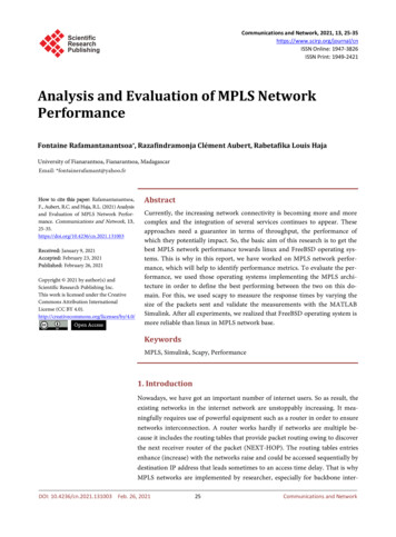
IP L3 vs. MPLS L3 VPNsVPN B VPN AVPN CVPN CMulticastIntranetVPN BVoIPVPN AHostingExtranetVPN AVPN BVPN CVPN A VPN BVPN COverlay VPNMPLS-Based VPNs ACLs, ATM/FR, IP tunnels, IPSec, etc.requiring n*(n-1) peering points Point to Cloud single point of connectivity Transport dependent Transport independent Groups endpoints, not groups Easy grouping of users and services Pushes content outside the network Enables content hosting inside the network Costs scale exponentially “Flat” cost curve NAT necessary for overlapping address space Supports private overlapping IP addresses Limited scaling Scalable to over millions of VPNs QoS complexity Per VPN QoS 2006 Cisco Systems, Inc. All rights reserved.29
How Does It Work?MPLS L3 VPN Control Plane BasicsiBGP—VPNv4Label ��VPNv4iBGP—VPNv4PE2CE1CE21. VPN service is enabled on PEs (VRFs are created and applied to VPN site interface)2. VPN site’s CE1 connects to a VRF enabled interface on a PE13. VPN site routing by CE1 is distributed to MP-iBGP on PE14. PE1 allocates VPN label for each prefix, sets itself as a next hop and relays VPN site routes to PE39. PE3 distributes CE1’s routes to CE2(Similar happens from CE2 side ) 2006 Cisco Systems, Inc. All rights reserved.30
How Does It Work?How Control Plane Information Is SeparatedVPN-IPv4Net RD:16.1/16NH PE1Route Target100:1Label 4216.1/16CE1iBGP—VPNv4 Label ExchangeP1No VPNroutes inthe Core(P)P2IGP/eBGPNet 16.1/16CE2IGP/eBGPNet 16.1/16IPv4 RouteExchangePE1PE2ip vrf YellowRD 1:100route-target export 1:100route-target import 1:100MPLS VPN Control Plane Components: Route Distinguisher: 8 byte field—unique value assigned by a provider to each VPN to make a route uniqueso customers don’t see each other’s routes VPNv4 address: RD VPN IP prefix; Route Target: RT-8bytes field, unique value assigned by a provider to define the import/export rules for theroutes from/to each VPN MP-BGP: facilitates the advertisement of VPNv4* prefixes labels between MP-BGP peers Virtual Routing Forwarding Instance (VRF): contains VPN site routes Global Table: Contains core routes, Internet or routes to other services 2006 Cisco Systems, Inc. All rights reserved.31
How Does It Work?How Data Plane Is SeparatedIPv4CE1P1IPv4CE1ForwardsIPv4 PacketIPv4IPv4CE2P2PE1IPv4PE2!Interface S1/0ip vrf forwarding Yellow!CE2ReceivesIPv4 Packet1. PE1 imposes pre allocated label for the prefix2. Core facing interface allocates IGP label3. Core swap IGP labels4. PE2 strips off VPN label and forwards the packet to CE2 as an IP packet 2006 Cisco Systems, Inc. All rights reserved.32
MPLS Security (1)Comparison with ATM/FR MPLS VPN security iscomparable to that provided byFR/ATM-based VPNs withoutproviding data encryptionCustomer may still use IPSecbased mechanisms e.g., CECE IPSec-based encryptionATM/FRMPLSAddress SpaceYesYesRoutingSeparationYesYesResistance toAttacksYesYesResistance toLabel SpoofingYesYes“CISCO MPLS-BASED VPNS: EQUIVALENT TOTHE SECURITY OF FRAME RELAY AND ATM”MIERCOM STUDY 2006 Cisco Systems, Inc. All rights reserved.33
MPLS VPN Services (2):Multicast VPNsMulticast SourceVPN AVPN BVPN AMulticast inthe coreMulticast ReceiverVPNaVPN AVPN AMPLS VPN NetworkVPN BVPN B ReceiverVPN BMulticast VRFVPN A Multicast SourceVPN BCriticality of more than selling connectivityRun multicast within an MPLS VPNnative multicast deployment in the coreSimplified CE provisioningHighly Efficient – Multicast trees built dynamically in the core as needed 2006 Cisco Systems, Inc. All rights reserved.34
Deployment Example I: Service ProviderProviding MPLS Services to SubscribersCustomerAVPN APE1VMHQ VPN AMPLS ServiceProviderP1P2FR/ATMVMPE2Branch OfficeLocal orDirectDial ISPProviderNetworksMPLS toIPsec/PECustomerAVPNBInternetRemote Users/TelecommutersPE3VMVMVPN BCustomer BBusinessPartnerVPN CServices Covering MAN and WAN areas:Intranet and Extranet L3 VPNs, Multicast VPNs, Internet VPN, Encryption &Firewall Services, Remote Access to MPLS Services .etc. 2006 Cisco Systems, Inc. All rights reserved.3535
Deployment Example II: MPLS VPN Subscriber with VPNs inCampus That Spans Across SP’s MPLS VPN NetworkC1-Hub SiteL2Egress PEMPLSServiceProviderIngressPECELayer 3Each SubInterfaceAssociated with differentVPN 2006 Cisco Systems, Inc. All rights reserved.L2Notice, Multi-VRFnot necessary atremote sitesMulti-VRFVPNRedVPNGreen802.1Q36
Deployment Example III: Full MPLS VPNin Enterprise Campus/LANCE (multi-VRF)L2 L2 Access Multi-VRF-CE atDistribution Multi-VRF betweencore and distributionPLayer 3 BGP/MPLS VPNs incore onlyPE w/VRFMP-iBGPVPN2L2VPN1802.1QBGP/MPLS VPN 2006 Cisco Systems, Inc. All rights reserved.37
Deployment Example IV: Full MPLS VPN inEnterprise WAN Subscribed MPLS VPNsEnterprise-AData Center 1Enterprise OwnedMPLS InternationalWANEnterprise-AData Center 3Enterprise-AData Center 2RegionalService Provider1MPLS BackboneRemote SitesEnterprise-A 2006 Cisco Systems, Inc. All rights reserved.RegionalService Provider2MPLS BackboneRemote SitesEnterprise-A38
Layer 2 VPNs 2006 Cisco Systems, Inc. All rights reserved.39
Layer 2 VPNsSimilar to L3 VPN Designate a label for the circuit Exchange that label information with the egress PE Encapsulate the incoming traffic (Layer 2 frames) Apply label (learned through the exchange) Forward the MPLS packet (l2 encapsulated todestination on an LSP) At the egress Look up the L2 label Forward the packet onto the L2 attachment circuit 2006 Cisco Systems, Inc. All rights reserved.40
Any Transport over MPLS ArchitectureAttachment CircuitEthernet VLAN, FR DLCI, ATM VC, PPP SessionVPN ACE11. L2 transport routeentered on ingress PE!PE1VPN A2. PE1 starts LDPsession with PE2 ifone does not alreadyexist!3. PE1 allocates VClabel for new interface& binds to configuredVC ID!4. PE1 sends labelmapping messagecontaining VC FECTLV & VC label TLV!CE2PE25. PE2 receives VCFEC TLV & VC labelTLV that matcheslocal VCID!Note: PE2 repeats steps 1-5 sothat bi-directional label/VCIDmappings are established!Draft Martini compliant sdescribes label distribution mechanisms for VC labelsdraft-martini-l2circuit-encap-mplsdescribes emulated VC encapsulation mechanisms 2006 Cisco Systems, Inc. All rights reserved.41
AToM: Frame Relay over MPLS ExampleDirected LDPLabel Exchange for VC1—Label 10Label Exchange for VC2—Label 21PE1DLCI 101DLCI 102FrameRelay10110 5010110 9010221 5010221 90Neighbor LDP— Neighbor LDP—Label 90Label 50CPE Router,FRADPE2DLCI 201DLCI 202FrameRelayMPLSBackboneCPE Router,FRADMPLS LSPAtoM TunnelPE1 Config:PE2 Config:connect FR1 serial5/0 101 l2transportmpls l2transport route 2.2.2.2 1connect FR1 serial5/0 201 l2transportmpls l2transport route 1.1.1.1 1VC1—Connects DLCI 101 to DLCI 201VC2—Connects DLCI 102 to DLCI 202 2006 Cisco Systems, Inc. All rights reserved.42
AToM Deployment ExampleCustomer ADatacenter1Ethernet o MPLS TunnelCE1Customer ADatacenter2Cells/frames withlabelscEthernet o MPLS TunnelCE1CE2PE1MPLSBackbonePECE2PE2PEATM o MPLS TunnelVirtual Leased LineATMATM o MPLS TunnelATMVirtual CircuitsCPE Routers 2006 Cisco Systems, Inc. All rights reserved.CPE Routers43
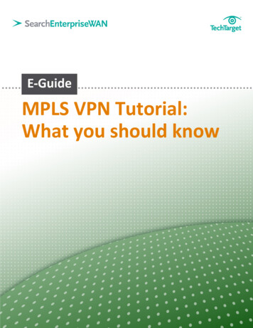
Virtual Private LAN Services (VPLS)102Attachment VCs arePort Mode or VLANIDCE1PE1MAC 1RootBridgePE3DataPE2MPLSCoreFormsTunnelLSPsMAC 1Common VC ID between PEscreates a Virtual SwitchingInstanceMAC 2201E0/0xxxDataMAC 1CE2 MAC 2Full mesh of directedLDP sessionsexchange VC labelsRootBridgeMAC Address AdjMAC 2MAC 1MAC xRootBridgeCE3MAC Address AdjMAC 2E0/1MAC 2MAC 1MAC x201102xxx VPLS defines an architecture that delivers Ethernet Multipoint Services (EMS) over an MPLSnetwork VPLS operation emulates an IEEE Ethernet bridge. Two VPLS drafts in existence Draft-ietf-l2vpn-vpls-ldp-01 Cisco’s implementation Draft-ietf-l2vpn-vpls-bgp-01 2006 Cisco Systems, Inc. All rights reserved.44
VPLS and H-VPLSVPLS192.168.11.1/24192.168.11.11/24VPLS Direct Attachment192.168.11.25/24192.168.11.2/24H-VPLS Two tier hierarchy MPLS or Ethernet edge MPLS core Single flat hierarchy MPLS to the POPPE-rsEthernet EdgePoint-to-Point or Ring 2006 Cisco Systems, Inc. All rights reserved.PWMPLS Coren-PEPE-POPPE-rsu-PEPE-CLEMTU-sMPLS Edge45
VPLS Components/Deployment ExampleAttachment CircuitCEn-PEn-PETunnel LSPCEPWCERed VSIBlue VSIGreen VSIDirected LDPSession BetweenParticipating PEsCEFull Mesh of PWsBetween VSIsCEn-PELegendCEn-PEVSIPWTunnel LSPCEPWCERed VSIBlue VSIGreen VSICEPW- Customer Edge Device- network facing-Provider Edge- Virtual Switch Instance- Pseudo-Wire- Tunnel Label Switch Path thatprovides PW transport 2006 Cisco Systems, Inc. All rights reserved.Blue VSIRed VSI (Common VC ID between PEscreates a VSI)46
MPLS TrafficEngineering 2006 Cisco Systems, Inc. All rights reserved.47
Why Traffic Engineering? Congestion in the network due to changing traffic patterns Election news, online trading, major sports events Better utilization of available bandwidth Route on the non-shortest path Route around failed links/nodes Fast rerouting around failures, transparently to users Like SONET APS (Automatic Protection Switching) Build new services—virtual leased line services VoIP toll-bypass applications, point-to-point bandwidth guarantees Capacity planning TE improves aggregate availability of the network 2006 Cisco Systems, Inc. All rights reserved.48
What Is MPLS Traffic Engineering? Process of routing data traffic in order to balance thetraffic load on the various links, routers, and switchesin the network Key in most networks where multiple parallel oralternate paths are available 2006 Cisco Systems, Inc. All rights reserved.49
Benefits of TE over Policy Routing Policy routing Hop-by-hop decision making No accounting of bandwidth Traffic engineering Headend-based Accounts for available link bandwidth Admission control 2006 Cisco Systems, Inc. All rights reserved.50
IP Routing and the FishR8R3R4R2R5R1R6R7IP (Mostly) Uses Destination-Based Least-Cost RoutingFlows from R8 and R1 Merge at R2 and Become IndistinguishableFrom R2, Traffic to R3, R4, R5 Use Upper RouteAlternate Path Under-Utilized 2006 Cisco Systems, Inc. All rights reserved.51
The Problem with B30 Some links are DS3, some are OC-3 Router A has 40mb of traffic for RouterF, 40mb of traffic for Router G Massive (44%) packet loss at RouterB Router E! Changing to A- C- D- E won’t helpRouter BRouter ARouter FOC-3OC-3Router EDS3DS3OC-3Router C 2006 Cisco Systems, Inc. All rights reserved.Router GDS3OC-3Router D52
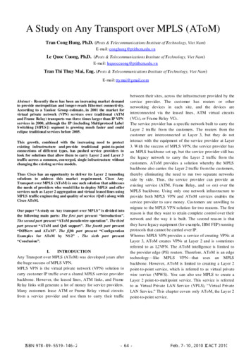
How MPLS TE Solves the ProblemNodeNext-HopCostBB10CC10DC20EB20FTunnel 030GTunnel 130 Router A sees all links Router A computes paths onproperties other than justshortest cost No link oversubscribed!Router BRouter ARouter FOC-3OC-3Router EDS340MbOC-3Router C 2006 Cisco Systems, Inc. All rights reserved.DS3Router GDS3OC-3Router D53
TE Fundamentals: “Building Blocks”Path Calculation—Uses IGPAdvertisements to Compute“Constrained” Paths1.2.3.4.5.Information DistributionPath selection/calculationPath setupTrunk admission controlForwarding traffic on totunnel6. Path maintenanceMIDPOINTsHEADENDIGP (OSPF or ISIS) Used toFlood Bandwidth InformationBetween RoutersUpstream 2006 Cisco Systems, Inc. All rights reserved.Unidirectional TunnelTAILENDRSVP/TE Used to DistributeLabels, Provide CAC, FailureNotification, Etc.Downstream54
Information Distribution You need a link-state protocol as your IGP IS-IS or OSPF Link-state requirement is only for MPLS-TE! Not a requirement for VPNs, etc.! Why do I need a link-state protocol? To make sure info gets flooded To build a picture of the entire network Information flooded includes link, bandwidth,attributes, etc. 2006 Cisco Systems, Inc. All rights reserved.55
Path Setup ExampleRESVRESVRESVTE HeadendPATHPATHTE TailendPATH PATH messages are sent withrequested bandwidth (&label) RESV messages are sent withlabel bindings for the TE tunnel Static routed Tunnels can be explicitly routed Policy route Admission control at each hop tosee if the bandwidthrequirement can be met 2006 Cisco Systems, Inc. All rights reserved. Packets are mapped to thetunnel via Autoroute Packets follow the tunnel—LSP56
Applications of MPLS TE:MPLS Fast RerouteR8R9R3R4R2R1R5R6R7Mimic SONET APSReroute in 50ms or Less Multiple hops can be by-passed; R2 swaps the label which R4expects before pushing the label for R6 R2 locally patches traffic onto the link with R6 2006 Cisco Systems, Inc. All rights reserved.57
Link ProtectionRouter ARouter BRouter DRouter ERouter YRouter XRouter C Primary tunnel: A B D E Backup tunnel: B C D (preprovisioned) Recovery 50ms*Actual Time Varies—Well Below 50ms in Lab Tests, Can Also Be Higher 2006 Cisco Systems, Inc. All rights reserved.58
Node ProtectionRouter ARouter B Router D Router ERouter FRouter YRouter XRouter C Primary tunnel: A B D E F Backup tunnel: B C E (pre-provisioned) Recovery 100ms 2006 Cisco Systems, Inc. All rights reserved.59
TE DeploymentScenarios 2006 Cisco Systems, Inc. All rights reserved.60
Tactical TE DeploymentRequirement: Need to Handle Scattered Congestion Points in the NetworkSolution:Deploy MPLS TE on Only Those Nodes That Face CongestionMPLS Traffic EngineeringTunnel Relieves Congestion PointsBulk of Traffic Flowe.g. Internet DownloadInternetService ProviderBackboneOversubscribedShortest Links 2006 Cisco Systems, Inc. All rights reserved.61
Full Mesh TE DeploymentRequirement: Need to Increase “Bandwidth Inventory” Across the NetworkSolution:Deploy MPLS TE with a Full Logical Mesh over a Partial PhysicalMesh and Use Offline Capacity Planning ToolService ProviderBackboneVPN Site AVPN Site BPartial Mesh ofPhysical Connections 2006 Cisco Systems, Inc. All rights reserved.Full Mesh of MPLSTraffic Engineering Tunnels62
1-Hop TE DeploymentRequirement: Need Protection Only—Minimize Packet LossLots of Bandwidth in the CoreSolution:Deploy MPLS Fast Reroute for Less than 50ms Failover Time with1-Hop Primary TE Tunnels and Backup Tunnel for EachService ProviderBackboneVPN Site AVPN Site BPrimary 1-Hop TE TunnelBackup TunnelPhysical Links 2006 Cisco Systems, Inc. All rights reserved.63
Virtual Leased Line DeploymentRequirement: Need to Create Dedicated Point-to-Point Circuits with BandwidthGuarantees—Virtual Leased Line (VLL)Solution:Deploy MPLS TE (or DS-TE) with QoS; Forward Traffic from L
VRF Aware GLBP TE AutoBandwidth TE MIB Static Label (LDP) MPLS VPNs - BGP LABEL for InterAS & CSC VRF Aware VRRP TE AutoBandwidth VPN MIB Static Cross Connect OSPF Sham Link VRF Aware DHCP Relay TE InterArea TE Support MPLS LSR MIB LDP Auto-enable VRF Lite VRF Aware NAT TE Forwarding Adjacency Support MPLS TE SNMP Notification