Transcription
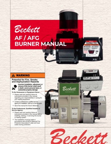
AF / AFGBURNER MANUALPotential for Fire, Smokeand Asphyxiation HazardsIncorrect installation, adjustment, ormisuse of this burner could resultin death, severe personal injury, orsubstantial property damage.To the Homeowner or Equipment Owner:yPlease read and carefully follow allinstructions provided in this manualregarding your responsibilities in caring foryour heating equipment.yContact a professional, qualified serviceagency for installation, start-up or service work.ySave this manual for future reference.To the Professional, Qualified Installer orService Agency:yPlease read and carefully follow allinstructions provided in this manual beforeinstalling, starting, or servicing this burneror heating system.yThe Installation must be made inaccordance with all NFPA (National FireProtection Association ) state and localcodes having jurisdiction.
To the Owner:Thank you for purchasing a Beckettburner for use with your heating appliance.Please pay attention to the Safety Warningscontained within this instruction manual.Keep this manual for your records andprovide it to your qualified service agencyfor use in professionally setting up andmaintaining your burner.Your Beckett burner will provide years ofefficient operation if it is professionallyinstalled and maintained by a qualifiedservice technician. If at any time the burnerdoes not appear to be operating properly,immediately contact your qualifiedservice agency for consultation.We recommend annual inspection/service of your heating system by aqualified service agency.Daily – Check the room in which yourburner/appliance is installed. Make sure:y Air ventilation openings are clean andunobstructedy Nothing is blocking burner inlet airopeningsy No combustible materials are storednear the heating appliancey There are no signs of fuel or waterleaking around the burner or applianceWeeklyy Check your fuel tank level. Alwayskeep your fuel tank full, especiallyduring the summer, in order to preventcondensation of moisture on the insidesurface of the tank.2ContentsGeneral Information. 3Hazard Definitions . 3 Remainder of manual to be used ONLY BYQUALIFIED SERVICE TECHNICIANS Inspect/Prepare Installation Site.6-7Inspect Chimney or Direct Vent System. 6Combustion air supply. 7Clearances to burner and appliance. 7Combustion chamber — Burner retrofitting. 7Prepare the Burner.8-9Burner fuel unit. 8Attach air tube (if not already installed). 8Nozzle and Pump Pressure. 8Install burner nozzle (if not already installed). 8Check/adjust electrodes. 9Servicing nozzle line assembly. 9Low Firing Rate Baffle. 9Mount Burner on Appliance.9-13Mounting options. 9Mounting dimensions. 9Check/Adjust ‘Z’ Dimension - ‘F’ heads. 10Installing the Fuel Tank and Supply System. 12-13Wire burner.13-14Burner packaged with appliance. 13Burner installed at jobsite. 13Special wiring required for burners with covers. 13Wiring. 14Burner Controls. 15Start Up Burner/Set Combustion.16-18Resetting from restricted or hard lockout. 16Cad Cell Resistance Measurement. 16Startup / Checkout. 17Check Safety Features. 17Set combustion with instruments. 17-18Perform Regular Maintenance. 18Shutting the Burner Off. 18Replacement Parts.19-22Start Up Report. 23Limited Warranty Information. 24
Section: General InformationGeneral InformationHazard DefinitionsIndicates a hazardous situation,which, if not avoided, will resultin death or serious injury.Indicates a hazardous situation,which, if not avoided, couldresult in death or serious injury.Indicates a hazardous situation,which, if not avoided, couldresult in minor or moderate injury.Within the boundaries of the hazard warning, there willbe information presented describing consequences if thewarning is not heeded and instructions on how to avoidthe hazard.Intended to bring special attentionto information, but not related topersonal injury or property damage.Owner’s ResponsibilityIncorrect installation, adjustment, anduse of this burner could result in severepersonal injury, death, or substantialproperty damage from fire, carbonmonoxide poisoning, soot or explosion.Contact a professional, qualified service agency for theinstallation, adjustment and service of your oil heatingsystem. This work requires technical training, tradeexperience, licensing or certification in some states andthe proper use of special combustion test instruments.Please carefully read and comply with the followinginstructions:y Never store or use gasoline or other flammableliquids or vapors near this burner or appliance.y Never attempt to burn garbage or refuse in thisappliance.y Never attempt to light the burner/appliance bythrowing burning material into the appliance.y Never attempt to burn any fuel not specified andapproved for use in this burner.y Never restrict the air inlet openings to the burner orthe combustion air ventilation openings in the room.This manual contains information that applies to both AF and AFG burners. These burners mayappear to be basically identical, but there are differences in design and performance. Pleasereview the comparison chart below:FeatureModel AFModel AFGApplicationAppliances with refractory chambers,natural draft in chamberSame as AF, plus: Appliances with minimal orno chamber, moderate chamber pressure.Blower wheel‘Strip’ construction3-11/16” WideTablock’ ConstructionAir Inlet AdapterInlet BellAir GuideAir Inlet Shutter8-Slot4-SlotApproved Air Tube Combinations“F” Series ONLY“F” or “M” SeriesGaskets - Igniter Baseplate/BarrierOptionalRequiredLow Firing Rate BaffleN/AMay be specified2-1/2” WideFigure 1. Burner label locationAFG Burner Manual3
Section: General InformationDo NOT Alter the OriginalBurner DesignTampering with or altering the burner design couldseriously impair performance, resulting in loss ofstatic pressure, damage to the system components,reduced air volume, heavy smoke, flameimpingement, appliance sooting, hot gas puff-back,and asphyxiation or fire hazards.Figure 2 – Burner SpecificationsCapacity(Note 1)AF Burner: 0.40 – 3.00 GPHAFG Burner: 0.40 – 3.00 GPHRefer to Figure 3, Page 5 for furtherinformationCertifications/ApprovalsANSI / UL296 andCSA – B140.0ApprovedFuelsUSA: ASTM D396 for No1 or No.2Heating Oil & B6 – B20 grades.Canada: No. 1 Stove Oil or No. 2 FurnaceOil Only.Electrical: InputVoltage120 VAC / 60Hz / 1 PhaseCurrent5.8 Amps MaximumMotorBeckett p/n 21805: 1/7 HP, 3450 RPM,PSC, NEMA 48IgniterBeckett p/n 51771: ElectronicSolid State rated for continuous duty.Fuel Pump(Note 2)Beckett p/n PF2032xSolenoid coil 120VACInlet Pressure: 3 psi maximumOutlet Pressure: 100-200 psiAir TubeCombinationsATC Codes and selection – See Figure 3,page 5Dimensions(Less Tube)Less Cover:Height: 10-3/8”Width: 12-1/2”Depth: 6-1/2”With Cover:Height: 10-3/8”Width: 12-1/2”Depth: 9-1/4”Air Tube: 4.0” ØOperatingTemperature(Note 3) 32 F (0 C) Minimum 140 F (60 C) MaximumEnvironmental5% to 95% RH, non-condensingMaintain the design to its original configuration.Only use parts specified for AF or AFG Burners.Do NOT remove the air guide from the AFG chassis.Do NOT use ‘M’ Series air tube combinations on AFBurners.Never try to convert an AF to an AFG or vice versaAny design alteration will:y Void UL Listingy Void manufacturer’s warrantiesy Seriously impact burner performancey Greatly increase your liability riskImpaired Burner Performanceand Fire Hazard.Do NOT operate the burner beyond specificationsoutlined in the following Table.y For applications beyond these limits, consult BeckettTechnical Service at 1-800-645-2876.y NOTE: Some packaged appliances with burnersmay be agency listed as a unit to operate beyondthese limits. Consult the appliance manufacturer’sspecifications and agency approvals for verification.Frozen Plumbing andWater Damage HazardIf the residence is unattended in severely coldweather, burner primary control safety lockout,heating system component failures, power outagesor other electrical system failures could result infrozen plumbing and water damage in a matter ofhours. For protection, take preventive actions suchas having a security system installed that operatesduring power outages, senses low temperatureand initiates an effective action. Consult with yourheating contractor or a home security agency.SEE WARNING SECTION BELOWNote 1: Approval Agency listings rate these burners for 0.40 – 3.00GPH. However, the firing rate range is limited by the specific air tubecombination being used. Refer to Figure 3, Page 5.Note 2: See appliance manufacturer’s burner specifications for recommended pump discharge pressure.Note 3: Operating temperatures above or below listed specificationsmust be approved by RW Beckett EngineeringUse ONLY Fuels Listed for Usewith this BurnerUse of unapproved fuels could result in explosion,fire, personal injury or death, and/or damage toequipment and property.y DO NOT USE Raw Vegetable Oil (RVO) or any fuelblended with RVOy DO NOT USE with Flammable Liquids; Gasoline, LP gas,charcoal lighter fluid, etc.y For a listing of alternative fuels please refer to the Beckett‘Alternative Fuels and Beckett Burners Technical Bulletin’Form # 664860.4
Section: General InformationFigure 3: Model AF / AFG Air Tube Combination (ATC) CodesFiring RateGPH (min-max)HeadStatic PlateSize (inches)-None2-3/4 UATC Codes For Usable Air Tube 0 - 0.75F03-3/8 XR0.75 - 1.25F32-3/4 XN0.85 - 1.35F42-3/4 WH0.85 - 1.65F62-3/4 YB1.10 - 2.00F122-3/4 XO1.65 - 2.50F222-3/4 XP2.50 - 130XSAF160XSModel AFG Type “M” Air Tube Combination (ATC) CodesFiring Rate GPH(min-max)HeadStatic PlateSize (inches)VenturiATC Codes For Usable Air Tube Lengths0.50 - 1.10L13-3/8 U8 holes0.50 - 1.00L22-3/4 U8 holesAFG50MPSSAFG70MPSSAFG90MPSS0.75 - 2.75V12-3/4 U8 BSSAFG70MBSSAFG90MBSSNote: ATC's for specific manufacturers are listed in the Beckett OEM Specification Guide and can also be found byvisiting www.beckettcorp.com.Special Requirements Burner and/or appliance installations in the UnitedStates must comply with NFPA 31 (National FireProtection Association) Standard for the Installationof Oil-Burning Equipment, NFPA 70 (NationalElectric Code), as well as all state and local codes(AHJ)Installations in Canada must comply with the latesteditions of CSA B139 (Installation Code for OilBurning Equipment), CSA Standard C22, Part 1(Canadian Electric Code), and all applicable localcodes.Concealed damage — If you discover damage tothe burner or controls during unpacking, notify thecarrier at once and file the appropriate claim.When contacting Beckett for service information —Please record the burner serial number (and haveavailable when calling or writing). You will find theserial number on the silver label located on the leftrear of the burner. Refer to Figure 1, Page 3Fuel Supply SystemCompatibilityThe fuel supply system design and components mustbe compatible with the fuel being used in the appliance.Follow all guidelines and best practices recommendedby the fuel supplier, NFPA 30 & NFPA 31, and anystate or local ordinances for safe storage, filtering,conditioning, and delivery to the burner.AFG Burner ManualProfessional ServiceRequiredIncorrect installation, adjustment, anduse of this burner could result in severepersonal injury, death, or substantialproperty damage from fire, carbonmonoxide poisoning, soot or explosion.Please read and understand the manual supplied withthis equipment. This equipment must be installed,adjusted and put into operation only by a qualifiedindividual or service agency that is:y Licensed or certified to install and provide technicalservice to oil heating systems.y Experienced with all applicable codes, standardsand ordinances.y Responsible for the correct installation andcommission of this equipment.y Skilled in the adjustment of oil burners usingcombustion test instruments.The installation must strictly comply with all applicablecodes, authorities having jurisdiction and the latestrevision of the National Fire Protection AssociationStandard for the installation of Oil-burning Equipment,NFPA 31 (or CSA-B139 and CSA-B140 in Canada).Regulation by these authorities take precedence overthe general instructions provided in this installationmanual.5
Section: Inspect/Prepare Installation SiteInspect/Prepare Installation SiteInspect Chimney or Direct Vent Systempiece of broken tile wedged in the chimney shouldbe removed.5. No other appliance connection should be made tothe same flue pipe.Fire, Smoke & AsphyxiationHazard6. The flue pipe should have an upward pitch towardthe chimney of at least 1/4” per foot of length. Itshould fit tightly and should not project into thechimney.y Carefully inspect the chimney or exhaust ventsystem.y Make sure it is properly sized and in good workingcondition.7. Any leakage between tiles, around clean-out doors,or around the vent pipe should be sealed.y Follow the instructions supplied by the appliancemanufacturer.y The installation must strictly comply with allapplicable codes, authorities having jurisdiction andthe latest revision of the National Fire ProtectionAssociation Standard NFPA 31 for the installation ofchimneys and vent sizing, (or CSA-B139 and CSAB140 in Canada).y Regulation by these authorities take precedenceover the general instructions provided in thisinstallation manual.1. Starting with minimum gph firing rate, the minimumsize recommended is 6” flue pipe with 8” X 8”inside chimney, unless specified otherwise by theappliance manufacturer.2. A chimney flue shall extend at least 3 feet abovethe highest point at which the chimney comes incontact with the roof, and not less than 2 feet abovethe highest roof surface or structure within 10 feethorizontally of the chimney. Refer to Figure 4.3. Any accumulation of soot or debris in chimneyoffsets should be removed.Insulated stainless steel chimney linersThe new designs of high efficiency oil furnaces andboilers in conjunction with flame retention oil burnersare more efficient. One result of increased efficiency islower flue gas temperatures. As flue gases rise in thechimney, they will cool and condense when they reachthe dew point. The condensation will mix with the sulphurin the flue gases creating sulphuric acid. The acid willattack the chimney mortar, brick and clay liners causingcorrosion, deterioration and blockage of the chimney.Eventually the blockage could prevent exhausting theflue gases. Instead, the flue gases could vent out thebarometric damper into the living space.Therefore, it is strongly recommended that an approvedinsulated stainless steel liner be installed. For those installations not requiring a chimney, suchas through-the-wall vented appliances, follow theinstructions given by the appliance and power venter(if used) manufacturers.4. Any obstructions such as a protruding joint or aFigure 4 – Chimney Design - Above the RoofNOTE: Correct chimney design is shown by dotted lines. Incorrect chimney design, as shown by the solid lines, mayresult in down-drafts.6
Section: Inspect/Prepare Installation SiteCombustion air supplyAdequate Combustionand Ventilation Air SupplyRequiredFailure to provide adequate air supply couldseriously affect the burner performance and result indamage to the equipment, asphyxiation, explosion orfire hazards.y The burner cannot properly burn the fuel if it is notsupplied with a reliable combustion air source.y Follow the guidelines in the latest editions of theNFPA 31 and CSA-B139 regarding providingadequate air for combustion and ventilation.Appliance located in confined spaceThe confined space should have two (2) permanentopenings: one near the top of the enclosure and onenear the bottom of the enclosure. Each opening shallhave a free area of not less than (1) one square inchper 1,000 BTU’s per hour of the total input rating of allappliances within the enclosure. The openings shallhave free access to the building interior, which shouldhave adequate infiltration from the outside.Exhaust fans and other air-using devicesSize air openings large enough to allow for all airusing devices in addition to the minimum area requiredfor combustion air. If there is any possibility of theequipment room developing negative pressure (becauseof exhaust fans or clothes dryers, for example), eitherpipe combustion air directly to the burner or provide asealed enclosure for the burner and supply it with its owncombustion air supply.Outside air kit applicationsRefer to separate instruction sheet(s) included with anyoutside air kit or power vent system being installed.Clearances to burner and appliance Provide space around burner and appliance for easyservice and maintenance.Check minimum clearances against those shownby the appliance manufacturer and by applicablebuilding codes.Combustion chamber — Burner retrofittingVerify that the appliance combustion chamber providesat least the minimum dimensions given in Figure 5.Figure 5. Chamber DimensionsChamber Dimensions 4121513.56-72.50161317147-83.00181418157-8Direct air supply and sidewall venting Some AFG burners are equipped with combustionair boots to allow use of outside air for combustion.Air boot kits are available to adapt most AF & AFGburners. Please refer to the Replacement Partssection on page 19-22.When sidewall venting appliances, carefullyfollow appliance and power venter instructions forinstallation and wiring.Follow the Outside Air KitInstructions ExactlyFailure to comply could result in impaired combustion,appliance soot-up, puffback of smoke, and fire orasphyxiation hazards.y Do not attempt to install outside air piping tothe burner without using the outside air kit andinstructions.AFG Burner Manual7
Section: Prepare the BurnerPrepare the BurnerBurner fuel unitVerify that the burner fuel unit is compatible with theoil supply system. For more details, refer to the pumpmanufacturer’s instructions provided with the burner.Figure 6. Nozzle Flow Rate by SizeNozzle flow rate U. S. gallons per hour of No. 2 fueloil when pump pressure (psig) is:Nozzlesize125 psi 140 psi 150 psi 175 psi 200 psi(rated at100 psig)Attach air tube (if not already installed)0.400.450.470.490.530.56If using a flange and gasket, slide them onto the air tube.Then attach the air tube to the burner chassis usingthe four sheet metal screws provided. Please refer toInstallation Instruction sheet included with flange Correct Nozzle and FlowRate RequiredIncorrect nozzles and flow rates couldresult in impaired combustion, underfiring, over-firing, sooting, puff-back ofhot gases, smoke and potential fire orasphyxiation hazards.Use only nozzles having the brand, flow rate (gph),spray angle and pattern specified by the appliancemanufacturer.Follow the appliance manufacturer’s specifications forthe required pump outlet pressure for the nozzle, sincethis affects the flow rate.y Nozzle manufacturers calibrate nozzle flow rates at100 psig.y When pump pressures are higher than 100 psig, theactual nozzle flow rate will be greater than the gphstamped on the nozzle body. (Example: A 1.00 gphnozzle at 140 psig 1.18 gph)y Securely tighten the nozzle (90 torque inch pounds).y For typical nozzle flow rates at various pressuresrefer to Figure 6.Nozzle and Pump PressureInstall burner nozzle (if not already installed)1. Remove the plastic plug protecting the nozzleadapter threads.2. Place a 3/4” open-end wrench on the nozzleadapter. Insert the nozzle into the adapter andfinger tighten. Finish tightening with a 5/8” open-endwrench. Use care to avoid bending the burner headsupport legs or electrodes. If you remove the headto replace the nozzle (type “L1”/“L2” or “V1” heads),carefully reconnect the head to the nozzle adapter,making sure that the head support makes contact withthe nozzle adapter shoulder. Refer to Figure 11 or 12Page 11.3. If the nozzle is already installed, remove the nozzleline assembly to verify that the nozzle size andspray pattern are correct for the application (perappliance manufacturer’s information). Verify thatthe electrode tip settings comply with Figure 8,Page 9.4. If the nozzle is not installed, obtain a nozzle fromthe manufacturer, having the capacity and sprayangle specified in the appliance manufacturer’sinformation. For conversions or upgrades, wheninformation is not available for the application:8
Section: Mount Burner on Appliance Refer to Figure 7 to select the mid-range nozzlespray angle for the head type being used. Fire the burner and make sure the combustionis acceptable and the flame is not impinging onchamber surfaces. If a shorter flame is needed, select a wider sprayangle. If a longer flame is needed, select anarrower spray angle. Either hollow or solid spray patterns may be used.If combustion results are not satisfactory with theselected spray pattern, try the other pattern.Figure 7. Nozzle Spray AnglesRecommended nozzle spray angles“F” head70 or 80 nozzle“L1” & “L2” head45 , 60 , or 70 nozzle“V1” head45 , 60 , or 70 nozzleThe dimensions shown below are for use with L2 headsand M series air tube combinations ending with an ‘N’suffix (example: AFG70MDAQN)5/32” Gap1/4” AboveCenter1/8” Nozzle-to-tipSpacing7. To replace the nozzle assembly, reverse the above stepsLow Firing Rate BaffleCheck the electrode tip settings. Adjust if necessaryto comply with the dimensions shown in Figure 8. Toadjust, loosen the electrode clamp screw and slide/rotateelectrodes as necessary. Securely tighten the clampscrew when finished.The AFG Low Firing Rate Baffle (LFRB) reduces theair flow and pressure. The LFRB is sometimes used forfiring rates under 1.00 gph as listed in Figure 9. Referto the appliance manufacturer’s instructions. Do notomit the LFRB when specified. Omitting the baffle whenspecified or installing the baffle when not specified couldresult in impaired burner performance.Servicing nozzle line assemblyFigure 9. AFG Reduced Firing Rates (with LFRB)Check/adjust electrodes1. Turn off power to burner before proceeding.2. Disconnect oil connector tube from nozzle line.3. Loosen the two screws securing igniter retainingclips and rotate both clips to release igniterbaseplate. Then tilt igniter back on its hinge.4. Remove splined nut.5. “F” head air tube. - Remove nozzle line assemblyfrom burner, being careful not to damage theelectrodes or insulators while handling. To easeremoval of long assemblies (over 9 inches), rotateassembly 180 from installed position after pullingpartially out of tube.6. “L1”, “L2”, and “V1” head air tubes. - Slide nozzleline assembly forward (further into air tube) so thehead clears the venturi opening. Then rotate thenozzle line assembly 90 so the nozzle line endpoints up. Pull the nozzle line assembly toward youand remove assembly from burner.Figure 8. – Electrode Tip AdjustmentStandard Dimensions for F, L1, and V1 Heads.5/32” Gap5/16” AboveCenter1/16” Nozzle-to-tipSpacingAFG Burner ManualBurner head typeLow Firing Rate Baffle installedF0up to 0.65 gphF3, L1, or L2up to 0.85 gphF4 or F6up to 0.90 gphV1up to 1.00 gphMount Burner on ApplianceMounting options1. Bolt the burner to the appliance using the factorymounted flange or an adjustable flange.Mounting dimensions1. When using the Beckett universal adjustable flange,mount the air tube at a 2 downward pitch unlessotherwise specified by the appliance manufacturer.2. Verify that the air tube installed on the burnerprovides the correct insertion depth. See Figure 14,page 12.3. The end of the air tube should normally be ¼” backfrom the inside wall of the combustion chamber.Never allow the leading edge of the head assemblyto extend into the chamber, unless otherwisespecified by the heating appliance manufacturer.Carefully measure the insertion depth when usingan adjustable flange. Verify the insertion depthwhen using a welded flange.9
Section: Mount Burner on ApplianceFigure 10. Check/Adjust ‘Z’ Dimension for ‘F’ Heads1-1/8”1-3/8”Burner DimensionsFor usable length A (inches)Dimension (inches)F HeadL1 HeadL2 HeadV1 HeadH(nozzle to head), 1/32N/A1/47/321/4L(Total tube length)A 1/2A 1/2A 1/2A 1/2R(electrode length), 1/4A 2-1/4A 1-1/8A 1-1/8A 1-1/8S(adapter to static plate), 1/16(Note 1)1-3/81-3/81-3/8Q(nozzle line length),A 15/16A 3/16A 3/16A N/AN/AN/A1-3/4Z(F head-no heat shield)(F head-with heat shield)(L1 head w/straight shroud)(L1/L2/V1 head w/conic shroud)Note 1: 1-3/8 for dimension A less than 4”; 1-5/8 for dimension A from 4” through 4-1/2 “,2-13/32 for dimension A greater than 4-1/2”.Adjust the ‘Z’ dimensionto the requiredspecification.Incorrect Adjustments could cause combustionproblems, carbon deposition from flameimpingement, heavy smoke generation and firehazard.Make all adjustments exactly as outlined in thefollowing information.10Check/Adjust ‘Z’ Dimension - ‘F’ heads1. The important ‘Z’ dimension is the distance from the faceof the nozzle to the flat face of the head (or heat shield, ifapplicable). This distance for F heads is 1-⅛” (1-⅜” if theair tube has a heat shield). The “Z” dimension is factoryset for burners shipped with the air tube installed. Evenif factory set, verify that the “Z” dimension has not beenchanged.2. Use the following procedure to adjust the “Z” dimension, ifit is not correct: Turn off power to the burner. Disconnect the oil connector tube from the nozzle line See above figure. Loosen the splined nut from thenozzle line. Loosen the hex head screw securing theescutcheon plate to the burner housing. Place the end of a ruler at the face of the nozzle and,using a straight edge across the head, measure thedistance to the face of the head. A Beckett T501 gaugemay also be used. Slide the nozzle line forward or back until thisdimension for F heads is 1-⅛” (1-⅜” to the face of theheat shield, if applicable). Tighten the hex head screw to secure the escutcheonplate to the burner chassis. Then tighten the splinednut and attach the oil connector tube.3. Recheck the “Z” dimension periodically when servicing toensure the escutcheon plate has not been moved. Youwill need to reset the “Z” dimension if you replace the airtube or nozzle line assembly. The Beckett Z gauge (partnumber Z-2000) is available to permit checking the Fhead “Z” dimension without removing the burner from theappliance.
Section: Mount Burner on ApplianceFigure 11. Check/Adjust ‘Z’ Dimension - L1 & L2 Heads2.Use the following procedure to adjust the “Z” dimension, if itis not correct: L1/L2 heads (see figure 8, page 9 for dimensions)1.Turn off power to the burner.Disconnect the oil connector tube from the nozzle line.Refer to figure. Loosen the splined nut from thenozzle line. Loosen the hex head screw securing theescutcheon plate to the burner housing.Place the end of a ruler at the leading edge of the headand, using a straight edge across the end of the airtube, measure the distance to the end of the tube. ABeckett T501 gauge may also be used.Slide the nozzle line forward or back until this dimensionis 1-3/8” for L1 & L2 heads if the tube has a straightshroud, or 1-3/4” if the air tube has a conic shroud.Tighten the hex head screw to secure the escutcheonplate to the burner chassis. Then tighten the splined nutan
Frozen Plumbing and Water Damage Hazard Figure 2 – Burner Specifications Capacity (Note 1) AF Burner: 0.40 – 3.00 GPH AFG Burner: 0.40 – 3.00 GPH Refer to Figure 3, Page 5 for further information Certifications/ Approvals ANSI / UL296 and CSA –
