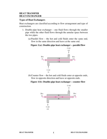
Transcription
Shell and Tube Heat ExchangersBasic CalculationsInstructor: Jurandir Primo, PE2012PDH Online PDH Center5272 Meadow Estates DriveFairfax, VA 22030-6658Phone & Fax: 703-988-0088www.PDHonline.orgwww.PDHcenter.comAn Approved Continuing Education Provider
www.PDHcenter.comPDHonline Course M371www.PDHonline.orgImperial and Metric UnitsJurandir Primo, PE 2010 Jurandir PrimoPage 2 of 32
www.PDHcenter.comPDHonline Course M371www.PDHonline.org1.0 Introduction:In intercoolers, boilers, pre-heaters and condensers inside power plants as well as other engineeringprocesses, heat exchangers are utilized for controlling heat energy. Heat exchangers are devices thatregulate efficient heat transfer from one fluid to another.There are two main types of heat exchangers. The first type of a heat exchanger is called the recuperative type, in which heat are exchangedon either side of a dividing wall by fluids; The second type is regenerative type, in which hot and cold fluids are in the same space whichcontain a matrix of materials which work alternately as source for heat flow.The optimum thermal design of a shell and tube heat exchanger involves the consideration of manyinteracting design parameters which can be summarized as follows:Process:1. Process fluid assignments to shell side or tube side.2. Selection of stream temperature specifications.3. Setting shell side and tube side pressure drop design limits.4. Setting shell side and tube side velocity limits.5. Selection of heat transfer models and fouling coefficients for shell side and tube side.Mechanical:1. Selection of heat exchanger TEMA layout and number of passes.2. Specification of tube parameters - size, layout, pitch and material.3. Setting upper and lower design limits on tube length.4. Specification of shell side parameters – materials, baffles cut, baffle spacing and clearances.5. Setting upper and lower design limits on shell diameter, baffle cut and baffle spacing.To develop calculations there are several software design and rating packages available, includingCodeware, Compress, Aspen BJAC, HTFS and CC-THERM, which enable the designer to study theeffects of the many interacting design parameters and achieve an optimum thermal design. 2010 Jurandir PrimoPage 3 of 32
www.PDHcenter.comPDHonline Course M371These packages are supported by extensivethermodynamic models.www.PDHonline.orgcomponent physical property databases and2.0 Concepts:The biggest problem in thermodynamics is the student to learn and recognize heat, work, force,energy, power and other technical terms. So to facilitate the basic comprehension of the terms used forshell and tube heat exchangers calculations it is very important to remember some concepts below:Cal - The “Cal” is the standard unit of measurement for heat. The gram calorie, small calorie or calorie(cal) is the amount of energy required to raise the temperature of one gram of water from 19.5 C to20.5 C under standard atmospheric pressure of 1.033 Kg/cm² (14.7 psi).Btu - British Thermal Unit: The “Btu” is the standard unit of measurement for heat. A Btu is defined asthe amount of energy needed to raise the temperature of one pound of water from 58.5 F to 59.5 Funder standard pressure of 30 inches of mercury (14.7 psi).UNIT1 Btu1 cal1 kcalMULTIPLYTO le - energy exerted by the force of one Newton acting to move an object through a distance of 1 m.UNIT1JMULTIPLYTO calkgf.mBtuft.lbfMULTIPLYTO 0.0009480.000284kWhphp (boiler)kcal/skgf.m/sft.lbf/sft.lbf/minBtu/ston (refrig)Watt – metrical unit for power.UNIT1W 2010 Jurandir PrimoPage 4 of 32
www.PDHcenter.comPDHonline Course M371www.PDHonline.org2.1. Temperature:Celsius (also known as centigrade) is a temperature scale that is named after the Swedish astronomerAnders Celsius (1701–1744), who developed a similar temperature scale two years before his death.Then nominally, 0 C was defined as the freezing point of water and 100 C was defined as the boilingpoint of water, both at a pressure of one standard atmosphere (1.033 Kg/cm²).Fahrenheit is the temperature scale proposed in 1724 by, and named after, the physicist Daniel GabrielFahrenheit (1686–1736). On the Fahrenheit scale, the freezing point of water was 32 degreesFahrenheit ( F) and the boiling point 212 F at standard atmospheric pressure (14.7 psi).Kelvin scale were named after the Scottish physicist William Thomson, 1st Baron Kelvin (1824–1907),who wrote of the need for an "absolute thermometric scale". The Kelvin and the degree Celsius are oftenused together, as they have the same interval, and 0 Kelvin is 273.15 degrees Celsius.C 5 (F - 32)9F 1.8 C(F 32)C K - 2732.2. Pressure:Pressure (symbol: P) is the force per unit area applied in a direction perpendicular to the surface of anobject. Gauge pressure is the pressure relative to the local atmospheric or ambient (Torr)pound-force persquare inch(psi)1 Pa1 N/m²0.000010.000009867 0.00750060.0001451 bar100000106 dyn/cm20.986775014.51 at980660.9806650.968735.514.2231 atm1013251.013251 atm76014.71 torr133.3220.0133320.00131581 mmHg0.01931 psi0.0068940.0689480.06804651.721 lbf/in²Energy Unit Conversions:UNIT1 Btu/s1 joule/kilogram/K J/(kg.K) 1 joule/kilogram/ C J/(kg. C) 2010 Jurandir 010.0002390.0002390.0002390.1020.0002390.000423TO OBTAINton (refrig)kWhpkgf.m/sft.lbf/sjoule/kilogram/ C J/(kg. C)joule/gram/ C J/(g. C)]kilojoule/kilogram/ C kJ/(kg. C)calorie /gram/ C cal/(g. C)kilocalorie /kilogram/ C kcal/(kg. C)kilocalorie /kilogram/K kcal/(kg.K)kilogram-force meter/kilogram/KBtu/pound/ F Btu/(lb. F)Btu/pound/ C Btu/(lb. C)Page 5 of 32
www.PDHcenter.comPDHonline Course M3711 Btu/pound/ F Btu/(lb w.PDHonline.orgkilocalorie /kilogram/ C kcal/(kg. C)Btu/pound/ C Btu/(lb. C)joule/kilogram/K J/(kg.K)joule/kilogram/ C J/(kg. C)joule/gram/ C J/(g. C)kilojoule/kilogram/K kJ/(kg.K)kilojoule/kilogram/ C kJ/(kg. pound/ R3. Basic Concept of Specific Heat:7.3Specific heat is defined as the amount of heat energy needed to raise 1 gram of a substance 1 C intemperature, or, the amount of energy needed to raise one pound of a substance 1 F in temperature.Q m.Cp. (T2 – T1)Where:Q heat energy (Joules) (Btu),m mass of the substance (kilograms) (pounds),Cp specific heat of the substance (J/kg C) (Btu/pound/ F),(T2 – T1 ) is the change in temperature ( C) ( F)The higher the specific heat, the more energy is required to cause a change in temperature. Substanceswith higher specific heats require more of heat energy to lower temperature than do substances with alow specific heat.Example 1:Using metric units and imperial units, how much energy is required to heat 350 grams (0.77 pounds) ofgold from 10 C (50 F) to 50 C (122 F)?Mass 350g 0.35 Kg 0.77 lbSpecific heat of gold 0.129 J/(g. C) 129 J/(Kg. C) x 0.000239 0.0308 Btu/(lb. F)Q m.Cp. (T2 – T1)Metric Units:Q (0.35 Kg) (129 J/(Kg. C) (50 C - 10 C)Q 1806 JConversion:1806 joules x 0.000947 1.71 BtuEvaluation in BtuQ m.Cp. (T2 – T1)Imperial Units:Q (0.77 lb) (0.0308 Btu/(lb. F) (122 F - 50 F) Q 1.71 Btu 2010 Jurandir PrimoPage 6 of 32
www.PDHcenter.comPDHonline Course M371www.PDHonline.orgConsult www.unitconversion.org (to convert energy units):Some samples of specific heat values are presented in the table below:Specific Heat Capacity - CpProduct(J/ g C)(Btu/lb oF)2.30.55Ammonia, 104 FCastor OilDowtherm4.861.81.551.160.430.37Freon R-12 saturated 0oFFuel Oil 10.1290.2170.50.530.5350.480.0308Light Oil, 60oF1.80.43Light Oil, 300 FMercuryOctaneOil, mineralOlive 0.470.51Propane, 32oFPropylene GlycolSodium chlorideSoya bean oilTolueneWater, ater, sea 36oF3.930.94Alcohol, ethyl 32oF (ethanol)oo 2010 Jurandir PrimoPage 7 of 32
www.PDHcenter.comPDHonline Course M371www.PDHonline.org4. Heat Exchangers Calculations:The main basic Heat Exchanger equation is:Q U x A x ΔTmThe log mean temperature difference ΔTm is:ΔTm (T1 – t2) – (T2 – t1)lnWhere: F(T1 – t2)(T2 – t1)T1 Inlet tube side fluid temperaturet2 Outlet shell side fluid temperatureT2 Outlet tube side fluid temperaturet1 Inlet shell side fluid temperatureWhen used as a design equation to calculate the required heat transfer surface area, the equation can berearranged to become:A Q/ (U x ΔTm)Where:A Heat transfer area (m²) (ft²)Q - Heat transfer rate (kJ/h) (Btu\h);U - Overall heat transfer coefficient (kJ/h.m². C) (Btu/hr. F)ΔTm - Log mean temperature difference ( C) ( F)And:Ct Liquid specific heat, tube side (kJ/kg. K) (Btu/lb. F)Cs Liquid specific heat, shell side (kJ/kg. K) (Btu/lb. F)4.1. The Overall Design Process:Design of a heat exchanger is an iterative (trial & error) process. Here is a set of steps for the process: Calculate the required heat transfer rate, Q, in Btu/hr from specified information about fluid flowrates and temperatures.Make an initial estimate of the overall heat transfer coefficient, U, based on the fluids involved.Calculate the log mean temperature difference, ΔTm, from the inlet and outlet temperatures of thetwo fluids.Calculate the estimated heat transfer area required, using: A Q/(U ΔTm).Select a preliminary heat exchanger configuration.Make a more detailed estimate of the overall heat transfer coefficient, U, based on the preliminaryheat exchanger configuration.Estimate the pressure drop across the heat exchanger. If it is too high, revise the heat exchangerconfiguration until the pressure drop is acceptable.If the new estimate of U is significantly different than the previous estimate, repeat steps 4through 7 as many times as necessary until the two estimates are the same to the desired degreeof accuracy.Input information needed. In order to start the heat exchanger design process, several items ofinformation are needed as follows:The two fluids involved need to be identified. 2010 Jurandir PrimoPage 8 of 32
www.PDHcenter.comPDHonline Course M371www.PDHonline.orgThe heat capacity of each fluid is needed.The required initial and final temperatures for one of the fluids are needed.The design value of the initial temperature for the other fluid is needed.An initial estimate for the value of the Overall Heat Transfer Coefficient, U, is needed.Knowing the first four items allows determination of the required heat transfer rate, Q, and the inlet andoutlet temperatures of both fluids, thus allowing calculation of the log mean temperature difference, ΔTm.With values now available for Q, U, and ΔTm, an initial estimate for the required heat transfer area can becalculated from the equation:A Q / (U . ΔTm)Example 2:1: Calculate a preliminary estimate of the heat exchanger area needed to cool 55,000 lb/hr of a light oil(specific heat 0.74 Btu/lb. F) from 190 F to 140 F using cooling water that is available at 50 F. Thecooling water can be allowed to heat to 90 F. An initial estimate of the Overall Heat TransferCoefficient is 120 Btu/hr.ft². F. Also estimate the required mass flow rate of cooling water.Solution: First calculate the required heat transfer rate for the above indicated light oil:Q m.Cp. (T2 – T1)Imperial Units:Q (55,000 lb/hr) (0.74 Btu/lb. F) (190 – 140) F 2,035,000 Btu/hr.Next calculate the log mean temperature difference:T1 Inlet tube side fluid temperature (light oil hot side 190 F)t2 Outlet shell side fluid temperature (water cold side 90 F)T2 Outlet tube side fluid temperature (light oil cold side 140 F)t1 Inlet shell side fluid temperature (water cold side 50 F)ΔTm (190 – 90) – (140 – 50)(190 – 90)(140 – 50) 2010 Jurandir Primo FlnPage 9 of 32
www.PDHcenter.comΔTm PDHonline Course M371(100) – (90)lnΔTm www.PDHonline.org F(100)(90)100.10536 94.9 FThe preliminary area estimate of the heat exchanger can now be calculated as:A Q / (U x ΔTm) A 2, 035, 000 Btu/hr(120Btu/h.ft². F).(94.9 F) 178.7 ft²The required mass flow rate of water can be calculated from Q m.Cp.ΔTm.Rearranging:m m QCp. ΔTm(2,035,000 Btu/hr) 28,978 lb/hr(0.74Btu/lb. F)(94.9 F)Example 3:Taking the shell and tube heat exchanger described in Example 1, how many tubes of 3 inch diameterand 10 ft length should be used?Solution: The surface area per tube will be:Sa πDL π (3/12) (10) ft² 7.854 ft² - (D – tube diameter in ft).The number of tubes required would thus be:n 178.7 ft²7.854 ft² 22.7 tubes (23 or 24 tubes).The next step would be to check on the pressure drop for this tube configuration and the specified flow. Ifthe pressure drop is acceptable, then the Overall Heat Transfer Coefficient (U) could be re-estimatedfor this heat exchanger configuration.4.2. Calculation Concepts:It is frequently necessary to determine the performance of a particular heat exchanger under conditionsof other than that for which it was designed.Input1. Overall Heat Transfer Coefficient “U” (Btu/hr.ft². F). For the heat exchanger under design.2. Area (ft²). Heat transfer area of the heat exchanger under consideration.3. Entering temperature hot ( F). Entering fluid temperature on the “hot” side of the heat exchanger.4. Entering temperature cold ( F). Entering fluid temperature on the “cold” side of the heat exchanger. 2010 Jurandir PrimoPage 10 of 32
www.PDHcenter.comPDHonline Course M371www.PDHonline.orgExample 4:Assume a redesign of a gasoline heat exchanger, area 8.9 ft², flow rate hot 8 gpm, operating on 135 Fto another heat exchanger operating on 150 F flow rate hot 10.30 gpm, using a Overall Heat Transf
www.PDHcenter.com PDHonline Course M371 www.PDHonline.org 2010 Jurandir Primo Page 4 of 32 These packages are supported by extensive component physical property databases and
