Transcription
e-ISSN: 2582-5208International Research Journal of Modernization in Engineering Technology and ScienceVolume:03/Issue:04/April-2021Impact Factor- 5.354www.irjmets.comCOMPARATIVE ANALYSIS OF RC STUCTURE AND TUBE IN TUBESTRUCTURE WITH AND WITHOUT SHEAR WALLSDr. Kiran T*1, Pooja Annarao Patil*2*1AssociateProfessor, Dept. of Civil Engineering, University VisvesvarayaCollege of Engineering, Bengaluru -560 056, Karnataka, India.*2PG student, Dept. of Structural Engineering, University VisvesvarayaCollege of Engineering, Bengaluru -560 056, Karnataka, India.ABSTRACTNow-a-days, with increase in population there is an endless demand for the tall buildings. In Tall Structureswhen Structural wall System and Braced System are insufficient to resist the lateral displacements and forcedemands on various structural members, in such cases more rigid Structural Systems that are tubularstructures are required like Frame Tube, Tube in Tube and Bundled Tube Systems, depending on the size andloads on the building. Tube in Tube is the advanced form of Framed tube structure which is widely usedbecause of its high strength and stiffness which effectively resists the lateral loads on the system. For presentstudy the modeling and analysis are done using ETABS V16 software 20-storey 3D model of RC structure alongwith tube in tube structure with and without shear wall models in seismic zone II are considered to study thetime period, base shear, lateral storey displacement and storey drift.Keywords: Tall Structure, Tubular Structure, Lateral loads, Seismic Analysis, Response Spectrum Analysis,Tube-in-Tube Structure, Shear walls, ETABS V16.I. INTRODUCTIONWith the endless growth in population, economic and urbanization all around the world there is increase in theuse of multi-storey buildings. As the height of the structure increases the effect of lateral loads such asEarthquake and Wind loads increases which affects the stability of the structure. To resist the effect of lateralloads on the buildings Tubular structures are found to be more efficient as tall structures. The TubularStructures are further classified into Frame Tube, Braced Tube, Bundled Tube, Tube in Tube, and Tube MegaFrame Structures. The Tube in Tube structures is the innovative and fresh concept in the tubular structures.Tube in Tube system is evolved form of Frame Tube System in which additional inner tube is provided withcore which can be utilized for stairs, elevator or lift. In the Tube in Tube structure the high strength concretecentral tube carries the major load.1.1 Tubular Structural SystemThe Tubular system was first introduced by Fazlur Rahman Khan from the firm Skidmore, Owings and Merrillin 1970s. In tall building design, the tube system is one of the common lateral stability systems. It is designed toact as a vertical cantilevered hollow shell cylinder. This allows creating an indefinite stiff “shell” around thebuilding exterior. When for the Tall Structures, Structural Wall System and Braced System are insufficient toresist the lateral displacements and force demands on various structural members, in such cases, more rigidStructural Systems that are tubular structures are required like Frame Tube, Tube-in-Tube and Bundled TubeSystems, depending on the size and loads on the building.1.2 Types of Tubular Structures1.2.3.4.5.Framed Tube StructureTube-in-Tube StructureBundled Tube StructureBraced Tube StructureTubed mega structure1.2.1 Framed Tube StructureThis is initial system type developed by Khan. It is the simplest form of the tube system which can be used on avariety of floor plan shapes such as square, rectangular, circular and freeform. The organization in the framedtube system is generally one of the closely spaced exterior columns and deep spandrel beams rigidly connectedwww.irjmets.com@International Research Journal of Modernization in Engineering, Technology and Science[351]
e-ISSN: 2582-5208International Research Journal of Modernization in Engineering Technology and ScienceVolume:03/Issue:04/April-2021Impact Factor- 5.354www.irjmets.comtogether, with the entire assemblage continuous along each facade and around the building corners. The systemis a logical extension of moment resisting frame whereby the beam and column stiffness are increaseddramatically by reducing the clear span dimensions and increasing the member depths. The lateral resistanceof this structure is provided by stiff moment resisting frames which form a tube throughout the periphery ofthe building.1.2.2 Tube-in-Tube StructureTube-in-Tube structure is new technology with advancement to the framed tube structure. They areframed tube structure formed by connecting outer-framed tube together with a core tube inside the structurewhich holds services such as utilities and lifts. These tubes are connected together by system of floordiaphragm and grid beams; in certain occasion they are connected through outriggers. As the columns of outerand inner core tubes are placed so closely, it is not seen as a solid system but it acts like a solid surface. Sinceouter-framed tube, “hull” is connected together with an internal elevator and service core; hence this system isalso termed as “hull-core structure”. There are some confusion between the concept of tube in tube and framedtube systems, in tube in tube system the inner tube and outer tube are pair of soft tubes especially the outertubes are not that stiffer .In framed tube systems the outer tube system is stiffer as they are composed ofclosely spaced columns connected by spandrel beams which make a very stiff outer tube. In the tube in tubestructure, the inner tube bends with the same horizontal deflection as the outer tube, owing to the high inplane stiffness of the floor slab, and carries a proportionate share of the lateral load.The Petronas tower is one the typical tube-in-tube structures.1.2.3 Bundled Tube StructureThe bundled tube system can be visualized as an assemblage of individual tubes resulting in multi-cell tube toresist the lateral loads. Together they resist the lateral loads and overturning moments. When the tubes arewithin the building envelope, the interior columns are positioned along their perimeters. The increase instiffness is apparent. The system allows for the greatest height and the most floor area. The bundle tube designis not only highly efficient in economic terms, but it also allows for more versatile building designs, adoptinginteresting shapes and bundled in dynamic groupings rather than being simply box-like towers. In this systemif internal webs are introduced, they will be a great reduction of the shear lag in the flange beams. Hence theircolumns are more uniformly stressed than in the single tube structures and they contribute more to the lateralstiffness.1.2.4 Braced Tube StructureBraced tube system also known as trussed tube is similar to that of frame tube system but it has fever exteriorcolumns spaced further apart. To compensate this fever column bracing or concrete shear walls are introducedto tie the columns together. By inter connecting all the exterior columns it forms a rigid box and is capable ofresisting lateral shears by axial in its members rather than through flexure. By having relatively large columnspacing it is possible to have lots of clear space for windows unlike in conventionally framed tube structures. Inbraced tube structures, the braces are provided to share the axial load from more highly stressed columns toless highly stressed columns and this phenomenon helps to lower the difference between load stresses incolumns.1.3 Shear wallsShear wall is a vertical element which is designed to resist lateral loads such as seismic and wind loads. Thesewalls generally start at foundation level and are continuous throughout the building height. Their thickness canbe as low as 150 mm, or as high as 400 mm in high rise buildings. Shear walls are usually provided along bothlength and width of buildings. Shear walls are like vertically-oriented wide beams that carry earthquake loadsdownwards to the foundation. They provide large strength and stiffness to the structure in the direction of theirorientation and thud reduces the lateral sway of the structure. By reducing the lateral sway it prevents thedamage to the structure and its content. Shear walls are oblong in cross-section, i.e., one dimension of the crosssection is much larger than the other. While rectangular cross-section is common, L- and U-shaped sections arealso used.www.irjmets.com@International Research Journal of Modernization in Engineering, Technology and Science[352]
e-ISSN: 2582-5208International Research Journal of Modernization in Engineering Technology and ScienceVolume:03/Issue:04/April-2021Impact Factor- 5.354www.irjmets.com1.4 objectives of the dissertation work1.2.3.4.5.Comparative Analysis of Tall RC Structure and Tube-in-tube Structure of with and without shear wallsusing ETABS v16.To study and compare the effect of seismic loads on RC Structure and Tube in tube Structure of with andwithout shear walls for zone II, considering medium soil.To study and compare the effect of shear walls in Tube in Tube Structure.To study and compare the lateral Storey Displacement, Storey Drift, Base Shear and Time Period, for RCStructure and Tube in tube Structure of with and without shear walls.To determine the most suitable system for the tall structures.II. METHODOLOGYIn this thesis, 4 models are modeled using finite element software ETABS V16 and are analyzed for dead, liveand earthquake loads by Response Spectrum Method.The steps followed to meet the objectives of the project are:1.Models of RCC Structure of 20 stories with floor height of 3m and Base storey height of 1.5m areconsidered.2.The Structure is assumed to be located in Zone II on Medium Soil as per IS:1893 (part 1)-2016 and Tubein-Tube structure with and without shear walls are modeled with reference to RCC Structure by usingETABS Software.3.All the models have constant floor height to get consistent results.4.Live load as per IS: 875 (part 2), dead load as per IS: 875(part 1) and seismic load as per IS: 1893-2002are applied and Response Spectrum Analysis is used.The results of the models are tabulated for base shear, maximum Storey displacement, time period andmaximum Storey drift from the software and are plotted to understand the difference in the behavior oflateral load resisting systems and to find the most suitable lateral resisting system.Based on the results obtained for different models conclusions are made.5.6.III. MODELING AND ANALYSIS3.1 Description of the ModelsThe study is carried out for 20 Storey tall RC Structure and the structure is modeled and analyzed usingETABSV16.Models considered for the analysis are:Model 1: RC StructureModel 2: Tube-in-Tube Structure with column spacing of 2.5mModel 3: Tube-in-Tube Structure with Shear coreModel 4: Tube-in-Tube Structure with peripheral Shear walls3.2 Structural Modeling in ETABSThe modeling and analysis are carried using ETAB V16 software. ETAB is advanced Analysis and DesignSoftware, used for design and analysis of building system. It has inbuilt graphical interface with ultimatemodeling and design procedures integrated using common database.Table 3.1: Parameters Considered for the Analysis.Sl. No.1.Design Data for All BuildingsDetails of BuildingiNumber of stories20iiType of buildingResidentialiiiStorey height3mivBuilding Plan Dimension42.5m x 27.5mvLocation of StructureBangalorewww.irjmets.com@International Research Journal of Modernization in Engineering, Technology and Science[353]
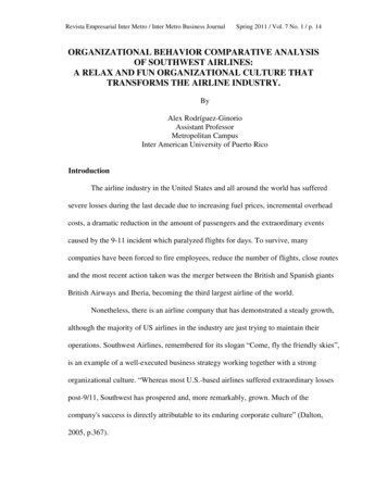
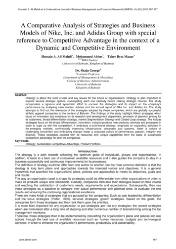
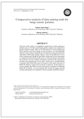
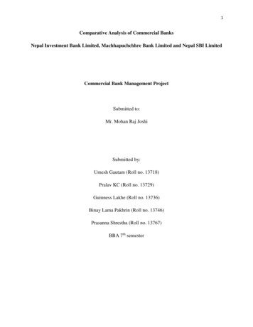
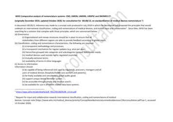
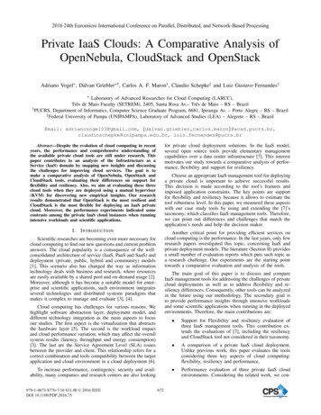
e-ISSN: 2582-5208International Research Journal of Modernization in Engineering Technology and ScienceVolume:03/Issue:04/April-20212.Material PropertiesiGrade of ConcreteImpact Factor- 5.354www.irjmets.comM25 for beams, slabs andshear walls.M40 for columns.iiGrade of Steel3.Section PropertiesiThickness of Slab150 mmiiSize of Beam300mm x 600 mmiiiFe500300mm x(exterior)Size of Column750mm300mm x 900 mm(interior)ivThickness of Shear Wall200 mmvThickness of Wall150 mm4.iLoads and Intensities2 kN/m2 for bedroomskitchenhallandbathrooms.Live Load on all the floors3 kN/m2 for corridors.iiRoof live load1.5 kN/m2 for terrace(accessible)iiiFloor Finish1.5 kN/m2ivTerrace Finish1.5 kN/m2vWall load3.96 kN/m²viParapet Wall load1 kN/m²5.Seismic Properties from IS: 1893 (part 1)-2016iZone factor0.1 (Zone II)iiImportance factor1.2iiiResponse reduction Factor3ivSoil TypeMedium3.3 Plan of modelsFigure1: Plan of RC structurewww.irjmets.comFigure 2: Plan of Tube-in-Tube structure@International Research Journal of Modernization in Engineering, Technology and Science[354]
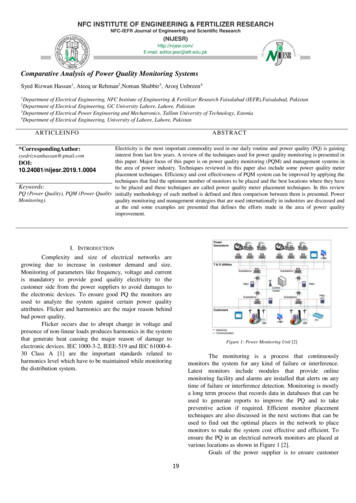
e-ISSN: 2582-5208International Research Journal of Modernization in Engineering Technology and ScienceVolume:03/Issue:04/April-2021Impact Factor- 5.354Figure 3: Plan of Tube-in-Tube with shear corewww.irjmets.comFigure 4: Plan of Tube-in-Tube with pheripheralshear walls3.4 Load combinationsThe load combinations for which the models are analyzed are:1.5(DL SPECX) and 1.5(DL SPECY) Where,DL Dead Load.SPEC Dynamic Earthquake Load (Response Spectrum Analysis).Analysis results are taken for above load combination for the parameters like base shear, storey displacement,storey drift and Time period.IV. RESULTS AND DISCUSSION4.1 STOREY DISPLACEMENTStorey displacement is the total displacement of any storey with respect to the ground and its maximumpermissible limit is prescribed in IS 1893-2002.As per IS: 1893-2002 the permissible limit for displacement is given by h/250, Where ‘h’ is the total height ofbuilding in millimetres (mm). For the present study the permissible limit for displacement is (58500/ 250) mm 234mm.The maximum storey displacement values and the percentage variation with respect to model 1 have beentaken for the load combinations of 1.5(DL SPECX) and 1.5(DL SPECY) as shown in table 4.1 and 4.2respectively and are plotted for the same as shown in figure 5 and 6.Table 4.1: Maxim
1.2.3 Bundled Tube Structure The bundled tube system can be visualized as an assemblage of individual tubes resulting in multi-cell tube to resist the lateral loads. Together they resist the lateral loads and overturning moments. When the tubes are within the building envelope, the interior columns are positioned along their perimeters. The increase in stiffness is apparent. The system allows .