Transcription
NASA/TM—2011-217001NETS–2011–3389Material Studies Related to the Use of NaK HeatExchangers Coupled to Stirling Heater HeadsIvan E. LocciUniversity of Toledo, Toledo, OhioCheryl L. Bowman and Steven M. GengGlenn Research Center, Cleveland, OhioMalcolm G. RobbieAnalex Corporation, Brook Park, OhioApril 2011
NASA STI Program . . . in ProfileSince its founding, NASA has been dedicated to theadvancement of aeronautics and space science. TheNASA Scientific and Technical Information (STI)program plays a key part in helping NASA maintainthis important role.The NASA STI Program operates under the auspicesof the Agency Chief Information Officer. It collects,organizes, provides for archiving, and disseminatesNASA’s STI. The NASA STI program provides accessto the NASA Aeronautics and Space Database andits public interface, the NASA Technical ReportsServer, thus providing one of the largest collectionsof aeronautical and space science STI in the world.Results are published in both non-NASA channelsand by NASA in the NASA STI Report Series, whichincludes the following report types: TECHNICAL PUBLICATION. Reports ofcompleted research or a major significant phaseof research that present the results of NASAprograms and include extensive data or theoreticalanalysis. Includes compilations of significantscientific and technical data and informationdeemed to be of continuing reference value.NASA counterpart of peer-reviewed formalprofessional papers but has less stringentlimitations on manuscript length and extent ofgraphic presentations.TECHNICAL MEMORANDUM. Scientificand technical findings that are preliminary orof specialized interest, e.g., quick releasereports, working papers, and bibliographies thatcontain minimal annotation. Does not containextensive analysis.CONTRACTOR REPORT. Scientific andtechnical findings by NASA-sponsoredcontractors and grantees. CONFERENCE PUBLICATION. Collectedpapers from scientific and technicalconferences, symposia, seminars, or othermeetings sponsored or cosponsored by NASA. SPECIAL PUBLICATION. Scientific,technical, or historical information fromNASA programs, projects, and missions, oftenconcerned with subjects having substantialpublic interest. TECHNICAL TRANSLATION. Englishlanguage translations of foreign scientific andtechnical material pertinent to NASA’s mission.Specialized services also include creating customthesauri, building customized databases, organizingand publishing research results.For more information about the NASA STIprogram, see the following: Access the NASA STI program home page athttp://www.sti.nasa.gov E-mail your question via the Internet to help@sti.nasa.gov Fax your question to the NASA STI Help Deskat 443–757–5803 Telephone the NASA STI Help Desk at443–757–5802 Write to:NASA Center for AeroSpace Information (CASI)7115 Standard DriveHanover, MD 21076–1320
NASA/TM—2011-217001NETS–2011–3389Material Studies Related to the Use of NaK HeatExchangers Coupled to Stirling Heater HeadsIvan E. LocciUniversity of Toledo, Toledo, OhioCheryl L. Bowman and Steven M. GengGlenn Research Center, Cleveland, OhioMalcolm G. RobbieAnalex Corporation, Brook Park, OhioPrepared for theNuclear and Emerging Technologies for Space (NETS–2011)cosponsored by the ANS Aerospace Nuclear Science and Technology Division, The ANS Trinity Section,and the AIAAAlbuquerque, New Mexico, February 7–10, 2011National Aeronautics andSpace AdministrationGlenn Research CenterCleveland, Ohio 44135April 2011
AcknowledgmentsThis work was performed for the NASA Exploration Technology Development Project and the Fission Power Systems project.The author gratefully acknowledges the excellent technical assistance of Joy Buehler in the metallographic lab, Terry McCueand David Hull in the microscopy lab, Mark Jaster, John Juhas and Adrienne Veverka in the furnace room, Timothy Ubienski,Joseph Lavelle, Aldo Panzanella (RIP), Anthony Kapucinski in the specimen machining group, Louis Ghosn for help on the FiniteElement Analysis (FEA), Robert Muto and Steve Prout from the American Brazing Company and Randy Bowman for excellenttechnical discussions.Trade names and trademarks are used in this report for identificationonly. Their usage does not constitute an official endorsement,either expressed or implied, by the National Aeronautics andSpace Administration.Level of Review: This material has been technically reviewed by technical management.Available fromNASA Center for Aerospace Information7115 Standard DriveHanover, MD 21076–1320National Technical Information Service5301 Shawnee RoadAlexandria, VA 22312Available electronically at http://www.sti.nasa.gov
Material Studies Related to the Use of NaK Heat ExchangersCoupled to Stirling Heater HeadsIvan E. LocciUniversity of ToledoToledo, Ohio 43606Cheryl L. Bowman and Steven M. GengNational Aeronautics and Space AdministrationGlenn Research CenterCleveland, Ohio 44135Malcolm G. RobbieAnalex CorporationBrook Park, Ohio 44142AbstractNASA has been supporting design studies and technology development that could provide power toan outpost on the Moon, Mars, or an asteroid. Technology development efforts have included fabricationand evaluation of components used in a Stirling engine power conversion system. Destructive materialevaluation was performed on a NaK shell heat exchanger that was developed by the NASA GlennResearch Center (GRC) and integrated with a commercial 1 kWe Stirling convertor from SunpowerIncorporated. The NaK Stirling test demonstrated Stirling convertor electrical power generation using apumped liquid metal heat source under thermal conditions that represent the heat exchanger liquid metalloop in a Fission Power Systems (FPS) reactor. The convertors were operated for a total test time of 66 hrat a maximum temperature of 823 K. After the test was completed and NaK removed, the heat exchangerassembly was sectioned to evaluate any material interactions with the flowing liquid metal. Severaldissimilar-metal braze joint options, crucial for the heat exchanger transfer path, were also investigated. Acomprehensive investigation was completed and lessons learned for future heat exchanger developmentefforts are discussed.IntroductionStirling engine power convertor technology is one option being explored for generating space-missionpower. Fission power offers robust, environment-independent flexibility and adaptability for a broadrange of space mission power requirements. The Fission Power Systems (FPS) Power ConversionMaterials Risk Reduction team has been tasked with reviewing the materials and fabrication options forthe free-piston Stirling power conversion candidate engine design. The Fission Surface Power System(FSPS) concept developed for the Moon and Mars would provide a net power of 40 kWe with a fullpower service life of 8 years (Fission Surface Power System Initial Concept Definition, 2010). Althoughthe hot-end temperatures are lower for a candidate FPS Stirling convertor than those used in othersuccessful systems, the relatively large heater head size and the NaK heat transfer fluid pose distinctchallenges. Recently two P2A (formerly known as EG-1000) 1 kWe free-piston Stirling powerconvertors, purchased from Sunpower Incorporated, were retrofitted with experimental heater headsfeaturing NaK heat exchangers designed by the NASA Glenn Research Center (GRC) to allow theconvertors to be interfaced with a pumped NaK loop at the NASA Marshall Space Flight Center (MSFC)(Mason, 2009). For this design, type 316L stainless steel (SS316L) is used as the exclusive containmentmaterial for the NaK. The convertors were operated at hot-end temperatures ranging from 673 to 823 K,cold-end temperatures from 303 to 343 K, and piston amplitudes ranging from 6 to 11 mm. The total NaKNASA/TM—2011-2170011
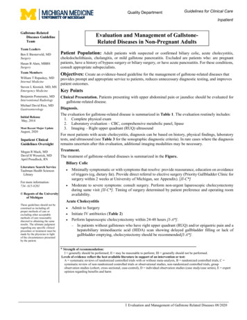
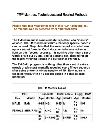
mass flow to both convertors ranged from 500 to 900 g/s. The NaK heat exchangers were operated for66 service hours, met all experimental objectives, and the test units operated as expected (Briggs, Geng,and Robbie, 2010). One of the two heat exchanger units was dissected to investigate potential materialinteractions and joint integrity.In addition to evaluating a specific technology development component, a second aspect of thisinvestigation concentrated on the evaluation of joining options for several designs of the powerconversion system hot-side heat exchanger (HX) components. Dissimilar metal joints are required toimpart both mechanical strength and thermal path integrity for a FPS-type heater head. Type 316Lstainless steel is the expected containment material for the flowing liquid metal NaK, but does not havethe mechanical strength desired for a thin-wall pressure vessel. Inconel 718 (IN718) is a stronger alloythat has been used in previous heater head designs, but would need to be bonded to stainless steel tomaintain a mono-metallic NaK flow loop. Either heater head envelop material probably would be bondedto a Cu heat acceptor to increase the surface area in contact with flowing He. This paper reports on theinitial evaluation of nickel-based, gold-based and copper-based braze materials to join the variouscombinations of these component materials options.Materials Inspection of NaK Heat ExchangerExamination of the Dome SectionThe integrated liquid metal heat exchanger / P2A heater head / convertor configuration for a singleconvertor is shown in Figure 1 (Briggs, Geng, and Robbie, 2010). The original fabrication design for theexperimental stainless steel heater head called for the various joints to be fabricated by electron beam(EB) welding. However, due to some fabrication issues and deadlines, most welds of the component werefabricated by gas tungsten arc welding (GTAW). Figure 1(b) shows the welded sections investigated afterthe NaK exposure. The initial sectioning for inspection of the heater head unit after the NaK exposure wasdone by wire electron discharge machining (EDM). The inlet and outlet pipes (cuts #1 and #2) wereremoved initially (Fig. 2(a)). The second major sectioning (cut #3) was done by splitting in half the maindome of the heat exchanger head (Fig 2(b)).Figure 1.—(a) Experimental NaK heater head installed on 1-kWe Stirling power convertor.(b) NaK heater head welded sections investigated.NASA/TM—2011-2170012
(b)(a)Cut #1Cut #3Cut #2Figure 2.—Initial sectioning by wire EDM of the NaK heat exchanger.(a)(b)PipeSectioninsert meetswhereJacketloopshelloutletpipeinsertdeformed theNaK jacket loopFigure 3.—(a) One-half section of the heater head showing assembly defects observed at the jacket loop/outlet pipewelding joint. (b) View of the gap left between the pipe insert and the heater head loop.The first noticeable shortcoming was observed at the joining section where the outlet pipe connectswith the jacket loop of the heater head as observed in the one-half section of the heater head (Fig. 3(a)). Agap (Fig. 3(b)) is clearly noticeable near the joint between the insert and the jacket wall. It is possible thatthe insert, used to connect the pipe to the jacket, may have pressed and deformed the jacket wall, orperhaps the TIG welding operation may have distorted the thin jacket wall. This gap could trap the liquidmetal and possibly create a crevice corrosion issue. “Metal bubbles”, sometimes described as nuggets,created during the welding operation, can also be observed in the interior of the jacket wall. Figure 4shows more detail of the metal bubbling features and the gap left between the insert and the wall jacket.A different fabrication situation occurred at the joining section where the inlet pipe connects to theheater head dome (Fig. 5). In this location, the pipe insert extended 1 to 2 mm beyond the head shelldome; this extension of the inlet pipe into the open section of the heat exchanger dome might create aflow disturbance in the liquid metal during operation, which could affect the heat transfer efficiency.NASA/TM—2011-2170013
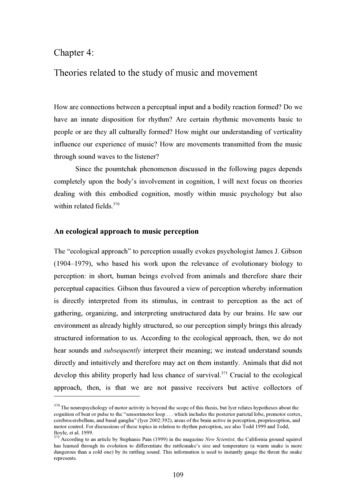
Figure 4.—Different view of the welding defects observedat the loop/outlet pipe joint. “metal bubbles” (nuggets) leftfrom the welding process and open gap are visible.Pipe insert extendedbeyond head shell domeFigure 5.—NaK heat exchanger used for the 1 kWe Stirling test at MSFCshowing the pipe insert extending 1 or 2 mm into the dome channel.Examination of the Internal Surfaces of the Connecting PipesFigure 6 shows an incomplete filled butt weld joint clearly visible by the presence of a groove orchannel inside the pipe. Localized internal oxidation near the heat affected zone (Fig. 6), revealed by thechange of surface coloration, will be discussed later in detail. Hot spot metal nuggets that can disturb theliquid metal flow are also observed in some regions of the butt weld.Imaging and measurement of the groove depth observed in these joints is reported and presented inFigure 7. The depth of the groove/channel is approximately 110 m and the width near the pipe surface isapproximately 300 m.A socket type weld which corresponds to an overlap of a pipe with an elbow, as shown in Figure 8,has left a step and an opening under the step, where liquid metal could penetrate and get trappedproducing a situation of localized or crevice corrosion. If this overlap assembly is needed, a second weldshould be made at end of the step to eliminate the possibility of any liquid metal concentration in theoverlap region.NASA/TM—2011-2170014
Figure 6.—Internal view of connecting pipe butt weld showing incomplete filling of thejoint and the presence of hot spot metal nuggets on the inside surface of the pipe.Figure 7.—Imaging and measurement of the groove/channel depthobserved in the butt weld after GTAW.Figure 8.—Section of the socket type weld that may require a second weldto eliminate the possibility of trapping liquid metal between the pipe andelbow walls.NASA/TM—2011-2170015
It was also noted that the welding of the support plates (Fig. 9), used to keep in place the pipes withrespect to the heater head, has penetrated inside the pipe, leaving a slightly bulging surface on the internalsurface of the pipe. These bulged surfaces might create non-desirable flow turbulence.Electron microscopy imaging and chemical analyses of regions near some of the incomplete filled weldsrevealed the presence of various oxide scales (Fig. 10) with varying degrees of detectable Na concentration.The Energy Dispersive Spectrum (EDS) presented in Figure 11, clearly reveals the presence of oxygen Oand Na in the vicinity of the groove/channel (Fig. 10). Semi quantitative chemical spot analyses in a regionnear the butt welded groove/channel revealed consistently the presence of Na in the oxidized region.Figure 9.—The welding of support plates for the pipes producedbulging surfaces inside the pipe.Figure 10.—Backscattered electron microcopyimage showing the groove, a partial view of anugget and oxide scales that formed in thevicinity of the butt weld. Area used for theEnergy Dispersive Spectroscopy (EDS)analysis presented in Figure 11 is indicated.Figure 11.—EDS chemical analysis of the oxide scale ofregion indicated in Figure 10, showing the presence ofO, Na, Fe, and Cr.NASA/TM—2011-2170016
Figure 12 shows a field emission scanning electron microscopy (FESEM) image of a polished crosssection of a region near the butt weld joint where a 8 m thick complex oxide scale is revealed. EDSanalyses (Fig. 13) indicates the presence of higher levels of Na, Cr, and O in the dark phase compared tothe white phase which seems to be enriched in Fe and Ni and, to a lesser degree, in Na. During theGTAW, the welded area (external region of the tubes) was protected from the environment by a shield ofinert gas (normally argon). Most likely, the inside of the tubes during welding did not benefit from theoutside gas shielding which resulted in a heat affected zone that oxidized during the joining operation.The presence of oxygen in liquid metals has been the subject of much research in the past (Hoffman,1967; Zimmerman, 1965; Hiltz, 1970). For many elements, the corrosion rate increases with the quantityof oxygen present in the alkali metal, and corrosion may be thought of as the interaction of the metalalkali oxide (i.e., Na2O) with the metal. In this fabrication assembly, oxide scales only formed in regionsat or near the welds. No oxide scales were observed in regions away from the welded joints. Therefore, asNaK was introduced to the system, the oxide scales that formed in the vicinity of welds reacted with theflowing NaK, probably resulting in the formation of complex oxides such as NaCrO2 and Na4FeO3(Barker and Wood, 1971).(b)(a)Figure 12.—(a) Low and (b) High magnification FESEM cross section images showing the complex oxide scale thatformed near a butt weld joint.Figure 13.—EDS analyses of the complex oxide scale phases that formedon the surface of the stainless steel tube.NASA/TM—2011-2170017
Brazing of Dissimilar MetalsA successful dissimilar-metal joint in this component application must provide mechanical integrity,thermal conductivity, and stability for the expected mission life at elevated temperatures. Brazing isfrequently a good approach for joining dissimilar metal in net-shape or near-net-shape configurations.Following is a summary of ongoing research on using commercially available braze alloys to join thevarious dissimilar metals that might be part of the heat exchanger. This summary focuses on downselecting candidate alloys based on physical integrity and chemical interactions. Future results will furtherdiscuss long-term stability. Joint configurations were selected based on expected heater head designs. Forexample one possible design, as shown in Figure 14, would require a joint between components made ofSS316L and IN718, and a secondary joint between IN718 and copper. A different design would require agood bond between SS316L steel and copper.Nickel- and gold-based braze alloys (Table 1) were selected to join the stainless steel and theInconel 718 superalloy in response to the first heater head design requirement; a second group of brazes(Table 2) were selected to join the type SS316L stainless steel to oxygen free high conductivity (OFHC)copper simulating an internal acceptor. Microstructural and mechanical properties results indicated thatgold-based brazes resulted in minimal reaction and property degradation with either base metal SS316Lor IN718 (Locci, Bowman, and Gabb, 2009). The phase reactions were observed to be more extensive inall the Ni-based brazes that were studied.The initial brazing work was done using a small brazing furnace at GRC. This furnace was used todefine the brazing parameters for the initial trials. Various exploratory runs were done simultaneously atthe American Brazing Company (Willoughby, Ohio), using one of their larger brazing furnaces. Thisstudy considered braze alloys in paste, tape, and foil form. Figure 15 shows examples of ring segmentsprepared with paste and foil braze material. Material coefficients of expansion and braze reservoirs mustalso be considered in the design. For example, a foil can be pre-placed between the faying surfaces priorto the initiation of the heating cycle if a gap exist or can be machined. Extra foil (Fig. 15(b)), extendingabove the rings, might need to be added to fill completely the gap that will be created at the brazingtemperature between the alloys.Blue boundary isSS316L heater headpiping and jacket, withNaK flowing at 850 KRed boundary indicates thecross section of the IN718heater head bonded to SS316LHeat acceptor, made of Cuwith fine passages to heatHe gas, bonded to IN718Figure 14.—Possible liquid metal heat exchanger assembly design.NASA/TM—2011-2170018
TABLE 1.—BRAZE ALLOYS EVALUATED TO JOIN SS316L AND IN718BrazesComposition (wt.%)FormBraze Temp(K)AMDRY 790Ni-1.74B-3.22SiPaste1403AMDRY 108Ni-23Cr-11.5Fe-4.2P-6.4SiPaste1403AMDRY 775Ni-15.38Cr-3.8BPaste1403Nioro82Au-18NiFoil (0.0254)1258 or 1273Palniro-770Au-22Ni-8PdFoil (0.0254)1323TABLE 2.—BRAZE ALLOYS EV
E-mail your question via the Internet to help@ sti.nasa.gov Fax your question to the NASA STI Help Desk at 443–757–5803 Telephone the NASA STI Help Desk at 443–757–5802 Write to: NASA Center for AeroSpace Info