Transcription
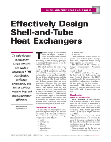
S H E L L- A N D - T U B E H E AT E X C H A N G E R SEffectively DesignShell-and-TubeHeat ExchangersTo make the mostof exchangerdesign software,one needs tounderstand STHEclassification,exchangercomponents, tubelayout, baffling,pressure drop, andmean temperaturedifference.Rajiv Mukherjee,Engineers India Ltd.hermal design of shell-and-tubeheat exchangers (STHEs) isdone by sophisticated computersoftware. However, a good understanding of the underlying principlesof exchanger design is needed to use thissoftware effectively.This article explains the basics of exchanger thermal design, covering suchtopics as: STHE components; classification of STHEs according to constructionand according to service; data needed forthermal design; tubeside design; shellsidedesign, including tube layout, baffling,and shellside pressure drop; and meantemperature difference. The basic equations for tubeside and shellside heattransfer and pressure drop are wellknown; here we focus on the applicationof these correlations for the optimum design of heat exchangers. A followup article on advanced topics in shell-and-tubeheat exchanger design, such as allocationof shellside and tubeside fluids, use ofmultiple shells, overdesign, and fouling,is scheduled to appear in the next issue.TComponents of STHEsIt is essential for the designer to have agood working knowledge of the mechanical features of STHEs and how they influence thermal design. The principalcomponents of an STHE are: shell; shell cover; tubes; channel; channel cover; tubesheet;CHEMICAL ENGINEERING PROGRESS FEBRUARY 1998 Copyright baffles; and nozzles.Other components include tie-rods andspacers, pass partition plates, impingement plate, longitudinal baffle, sealingstrips, supports, and foundation.The Standards of the Tubular ExchangerManufacturersAssociation(TEMA) (1) describe these various components in detail.An STHE is divided into three parts:the front head, the shell, and the rearhead. Figure 1 illustrates the TEMAnomenclature for the various constructionpossibilities. Exchangers are described bythe letter codes for the three sections —for example, a BFL exchanger has a bonnet cover, a two-pass shell with a longitudinal baffle, and a fixed-tubesheet rearhead.Classificationbased on constructionFixed tubesheet. A fixed-tubesheetheat exchanger (Figure 2) has straighttubes that are secured at both ends totubesheets welded to the shell. The construction may have removable channelcovers (e.g., AEL), bonnet-type channelcovers (e.g., BEM), or integral tubesheets(e.g., NEN).The principal advantage of the fixedtubesheet construction is its low cost because of its simple construction. In fact,the fixed tubesheet is the least expensiveconstruction type, as long as no expansion joint is required.Other advantages are that the tubes canbe cleaned mechanically after removal of1997 American Institute of Chemical Engineers. All rights reserved. Copying and downloading permitted with restrictions.
S H E L L- A N D - T U B E H E AT E X C H A N G E R SStationary Head TypesShell TypesERear Head TypesLAFixed Tube SheetLike "A" Stationary HeadOne-Pass ShellRemovable Channel and CoverMFFixed Tube SheetLike "B" Stationary HeadTwo-Pass Shellwith Longitudinal BaffleBNGFixed Tube SheetLike "C" Stationary HeadBonnet (Integral Cover)Split FlowPOutside Packed Floating HeadHCDouble Split FlowIntegral With TubesheetRemovable CoverSFloating Head with Backing DeviceJDivided FlowTNPull-Through Floating HeadChannel Integral With Tubesheetand Removable CoverKUKettle-Type ReboilerU-Tube BundleDWXSpecial High-Pressure ClosuresCross Flow Figure 1. TEMA designations for shell-and-tube heat exchangers.CHEMICAL ENGINEERING PROGRESS FEBRUARY 1998Externally SealedFloating Tubesheet
the channel cover or bonnet, and thatleakage of the shellside fluid is minimized since there are no flanged joints.A disadvantage of this design isthat since the bundle is fixed to theshell and cannot be removed, the outsides of the tubes cannot be cleanedmechanically. Thus, its application islimited to clean services on the shellside. However, if a satisfactory chemical cleaning program can be employed, fixed-tubesheet constructionmay be selected for fouling serviceson the shellside.In the event of a large differentialtemperature between the tubes andthe shell, the tubesheets will be unable to absorb the differential stress,thereby making it necessary to incorporate an expansion joint. This takesaway the advantage of low cost to asignificant extent.U-tube. As the name implies, thetubes of a U-tube heat exchanger(Figure 3) are bent in the shape of aU. There is only one tubesheet in a Utube heat exchanger. However, thelower cost for the single tubesheet isoffset by the additional costs incurredfor the bending of the tubes and thesomewhat larger shell diameter (dueto the minimum U-bend radius), making the cost of a U-tube heat exchanger comparable to that of a fixedtubesheet exchanger.The advantage of a U-tube heatexchanger is that because one end isfree, the bundle can expand or contract in response to stress differentials. In addition, the outsides of thetubes can be cleaned, as the tube bundle can be removed.The disadvantage of the U-tubeconstruction is that the insides of thetubes cannot be cleaned effectively,since the U-bends would require flexible-end drill shafts for cleaning.Thus, U-tube heat exchangers shouldnot be used for services with a dirtyfluid inside tubes.Floating head. The floating-headheat exchanger is the most versatiletype of STHE, and also the costliest.In this design, one tubesheet is fixedrelative to the shell, and the other isfree to “float” within the shell. Thispermits free expansion of the tubebundle, as well as cleaning of boththe insides and outsides of the tubes.Thus, floating-head SHTEs can beused for services where both theshellside and the tubeside fluids aredirty — making this the standard construction type used in dirty services,such as in petroleum refineries.There are various types of floating-head construction. The two mostcommon are the pull-through withbacking device (TEMA S) and pullthrough (TEMA T) designs.The TEMA S design (Figure 4) isthe most common configuration inthe chemical process industries (CPI).The floating-head cover is securedagainst the floating tubesheet by bolting it to an ingenious split backingring. This floating-head closure is located beyond the end of the shell andcontained by a shell cover of a largerdiameter. To dismantle the heat , the shell cover is removedfirst, then the split backing ring, andthen the floating-head cover, afterwhich the tube bundle can be removed from the stationary end.In the TEMA T construction (Figure 5), the entire tube bundle, including the floating-head assembly, canbe removed from the stationary end,since the shell diameter is larger thanthe floating-head flange. The floatinghead cover is bolted directly to thefloating tubesheet so that a split backing ring is not required.The advantage of this constructionis that the tube bundle may be removed from the shell without removing either the shell or the floatinghead cover, thus reducing maintenance time. This design is particularly suited to kettle reboilers having adirty heating medium where U-tubescannot be employed. Due to the enlarged shell, this construction has thehighest cost of all exchanger et(StationaryHead)Tie Rodsand Spacers Figure 2. Fixed-tubesheet heat exchanger.HeaderTubeplateShellTubesBaffles Figure 3. U-tube heat exchanger.FEBRUARY 1998 CHEMICAL ENGINEERING PROGRESS
S H E L L- A N D - T U B E H E AT E X C H A N G E R SThere are also two types of packedfloating-head construction — outsidepacked stuffing-box (TEMA P) andoutside-packed lantern ring (TEMAW) (see Figure 1). However, sincethey are prone to leakage, their use islimited to services with shellside fluids that are nonhazardous and nontoxic and that have moderate pressures and temperatures (40 kg/cm2and 300 C).Classificationbased on serviceBasically, a service may be singlephase (such as the cooling or heatingof a liquid or gas) or two-phase (suchas condensing or vaporizing). Sincethere are two sides to an STHE, thiscan lead to several combinations ofservices.Broadly, services can be classifiedas follows: single-phase (both shellside andtubeside); condensing (one side condensing and the other single-phase); vaporizing (one side vaporizingand the other side single-phase); and condensing/vaporizing (one sidecondensing and the other sidevaporizing).The following nomenclature isusually used:Heat exchanger: both sides singlephase and process streams (that is,not a utility).Cooler: one stream a process fluidand the other cooling water or air.Heater: one stream a process fluidand the other a hot utility, such assteam or hot oil.Condenser: one stream a condensing vapor and the other cooling wateror air.Chiller: one stream a processfluid being condensed at sub-atmospheric temperatures and the other aboiling refrigerant or process stream.Reboiler: one stream a bottomsstream from a distillation column andthe other a hot utility (steam or hotoil) or a process stream.This article will focus specificallyon single-phase applications.Design dataBefore discussing actual thermaldesign, let us look at the data thatmust be furnished by the process licensor before design can begin:1. flow rates of both streams.2. inlet and outlet temperatures ofboth streams.3. operating pressure of bothstreams. This is required for gases,especially if the gas density is notfurnished; it is not really necessaryfor liquids, as their properties do notvary with pressure.4. allowable pressure drop forboth streams. This is a very importantparameter for heat exchanger design.Generally, for liquids, a value of0.5–0.7 kg/cm2 is permitted per shell.A higher pressure drop is usually warranted for viscous liquids, especiallyin the tubeside. For gases, the allowedvalue is generally 0.05–0.2 kg/cm2,with 0.1 kg/cm2 being typical.5. fouling resistance for bothstreams. If this is not furnished, thedesigner should adopt values specified in the TEMA standards or basedon past experience.6. physical properties of bothstreams. These include viscosity,thermal conductivity, density, andspecific heat, preferably at both inletand outlet temperatures. Viscositydata must be supplied at inlet andoutlet temperatures, especially forliquids, since the variation with temperature may be considerable and isirregular (neither linear nor log-log).7. heat duty. The duty specifiedshould be consistent for both theshellside and the tubeside.8. type of heat exchanger. If notfurnished, the designer can choosethis based upon the characteristics ofthe various types of construction described earlier. In fact, the designer isnormally in a better position than theprocess engineer to do this.9. line sizes. It is desirable tomatch nozzle sizes with line sizes toavoid expanders or reducers. However, sizing criteria for nozzles are usually more stringent than for lines, especially for the shellside inlet. Conse-CHEMICAL ENGINEERING PROGRESS FEBRUARY 1998quently, nozzle sizes must sometimesbe one size (or even more in exceptional circumstances) larger than thecorresponding line sizes, especiallyfor small lines.10. preferred tube size. Tube sizeis designated as O.D. thickness length. Some plant owners have apreferred O.D. thickness (usuallybased upon inventory considerations),and the available plot area will determine the maximum tube length.Many plant owners prefer to standardize all three dimensions, againbased upon inventory considerations.11. maximum shell diameter. Thisis based upon tube-bundle removal requirements and is limited by crane capacities. Such limitations apply only toexchangers with removable tube bundles, namely U-tube and floating-head.For fixed-tubesheet exchangers, theonly limitation is the manufacturer’sfabrication capability and the availability of components such as dishedends and flanges. Thus, floating-headheat exchangers are often limited to ashell I.D. of 1.4–1.5 m and a tubelength of 6 m or 9 m, whereas fixedtubesheet heat exchangers can haveshells as large as 3 m and tubeslengths up to 12 m or more.12. materials of construction. Ifthe tubes and shell are made of identical materials, all components shouldbe of this material. Thus, only theshell and tube materials of construction need to be specified. However, ifthe shell and tubes are of differentmetallurgy, the materials of all principal components should be specifiedto avoid any ambiguity. The principalcomponents are shell (and shellcover), tubes, channel (and channelcover), tubesheets, and baffles.Tubesheets may be lined or clad.13. special considerations. Theseinclude cycling, upset conditions, alternative operating scenarios, andwhether operation is continuous orintermittent.Tubeside designTubeside calculations are quitestraightforward, since tubeside flow
represents a simple case of flowthrough a circular conduit. Heat-transfer coefficient and pressure drop bothvary with tubeside velocity, the lattermore strongly so. A good design willmake the best use of the allowablepressure drop, as this will yield thehighest heat-transfer coefficient.If all the tubeside fluid were toflow through all the tubes (one tubepass), it would lead to a certain velocity. Usually, this velocity is unacceptably low and therefore has to be increased. By incorporating pass partition plates (with appropriate gasketing) in the channels, the tubeside fluidis made to flow several times througha fraction of the total number of tubes.Thus, in a heat exchanger with 200tubes and two passes, the fluid flowsthrough 100 tubes at a time, and thevelocity will be twice what it wouldbe if there were only one pass. Thenumber of tube passes is usually one,two, four, six, eight, and so on.Heat-transfer coefficientThe tubeside heat-transfer coefficient is a fu
tube heat exchanger. However, the lower cost for the single tubesheet is offset by the additional costs incurred for the bending of the tubes and the somewhat larger shell diameter (due to the minimum U-bend radius), mak-ing the cost of a U-tube heat ex-changer comparable to that of a fixed-tubesheet exchanger. The advantage of a U-tube heat