Transcription
SUBCOURSESS0002EDITIONAU S ARMY SIGNAL CENTER AND FORT GORDONINTRODUCTION TO TACTICAL RADIOCOMMUNICATIONSDEVELOPMENT DATE: MARCH 1993
INTRODUCTION TO TACTICAL RADIO COMMUNICATIONSSubcourse Number SS0002EDITION AUnited States Army Signal Center and Fort GordonFort Gordon, Georgia 30905-50006 Credit HoursEdition Date: March 1993SUBCOURSE OVERVIEWThis subcourse presents the basic theory of radio operation, thedifferent types of tactical radios currently in use, and basictactical radio communications procedures.There are no prerequisites for this subcourse.This subcourse reflects the doctrine which was current at the time itwas prepared. In your own work situation, always refer to the latestofficial publications.Unless otherwise stated, the masculine gender of singular pronouns isused to refer to both men and women.TERMINAL LEARNING OBJECTIVEACTION:Identify and describe the basic principles of radiocommunications and apply those principles to tacticalradio communications. You will also become familiar edures currently in use in the field. You will alsolearn about the organization, equipment capabilities, andprocedures for the Single-Channel Ground and AirborneRadio System and improved high frequency radio systems.CONDITION:You will be given information from this subcourse.STANDARD:To demonstrate competency of this task, you must achievea minimum score of 70% on the subcourse examination.iSS0002
TABLE OF CONTENTSSectionPageSubcourse Overview . iAdministrative Instructions . iiiGrading and Certification Instructions . iiiLesson 1:Introduction to Tactical Radio Communications Theory . 1-1Practice Exercise . 1-29Answer Key and Feedback . 1-30Lesson 2:Tactical Continuous Wave and Voice Radio Equipment . 2-1Practice Exercise . 2-9Answer Key and Feedback . 2-12Lesson 3:Tactical Radio Voice Operation . 3-1Practice Exercise . 3-21Answer Key and Feedback . 3-22Lesson 4:Tactical Radio Teletypewriter Equipment . 4-1Practice Exercise . 4-9Answer Key and Feedback . 4-10Lesson 5:Single-Channel Ground and Airborne Radio System (SINCGARS)and Improved High Frequency Radio (IHFR) Operation . 5-1Practice Exercise . 5-13Answer Key and Feedback . 5-14Examination . E-1Appendix: List of Acronyms . A-1Student Inquiry SheetsiiSS0002
THIS PAGE INTENTIONALLY LEFT BLANK.iiiSS0002
THIS PAGE IS INTENTIONALLY LEFT BLANK.ivSS0002
LESSON 1INTRODUCTION TO TACTICAL RADIO COMMUNICATIONS THEORYCRITICAL TASKS: 01-5878.04-0005,01-5778.07-0003, 01-5778.07-0007OVERVIEWLESSON DESCRIPTION:In this lesson you will learn the basic theory of tactical radiocommunications including types of modulation (frequency modulation(FM) and amplitude modulation (AM)), transmission characteristics forvarious frequency ranges, antenna characteristics, and how to selectan antenna for a specific communications task.TERMINAL LEARNING OBJECTIVE:ACTIONS:a. Describetheoperationofabasicfrequencymodulation, amplitude modulation/double sideband, andamplitude modulation/single sideband transmitter andreceiver.b. Define transmission characteristics of high frequency(HF), very high frequency (VHF), and ultra highfrequency (UHF) radio waves.c. Select tactical antennas for specific tactical radiotransmission requirements.d. Determine the antenna polarization to obtain optimumcommunications when using tactical radio sets.e. Recognize and describe the four conditions that mustbe considered for compatibility between differentradio sets.CONDITION:You will be given information from this lesson.STANDARD:To demonstrate competency of the terminal learningobjective, you must achieve a minimum score of 70% on thesubcourse examination.REFERENCES: The material contained in this lesson was derived fromthe following publication: FM 24-18.1-1SS0002
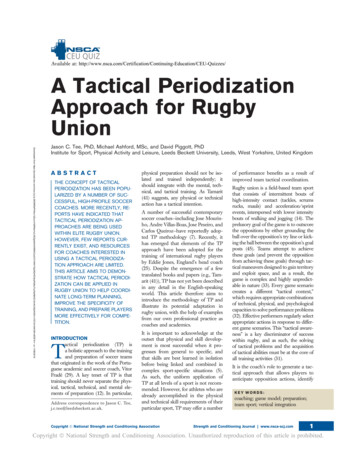
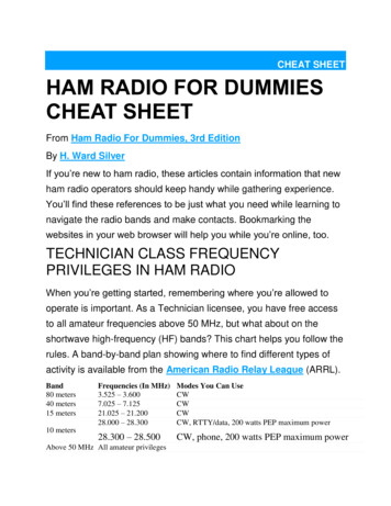
INTRODUCTIONThe advent of modern transportation has changed the face of thebattlefield immensely.Gone are the days when the messenger couldrun through the trenches to the headquarters tent with on urgentmessage for the Officer in Charge. Today that headquarters may be asmuch as 500 miles away, and that is a little too far even for thehardiest marathon runner.We must now rely on other moresophisticated means to get messages from the front lines to the"Headquarters Tent."In addition, the introduction of aircraft tothe modern battlefield has added a third dimension to the way we mustthink about coordinating our forces.The medium that brings all the elements of the modern battlefieldtogether and ensures a coordinated effort is radio.The radio hasbecome the central nervous system of the battlefield, keeping eachelement informed of the progress of the whole.As signal officers,it is your job to ensure that these nerves function properly andefficiently. You must be able to make the very best use of each andevery piece of equipment assigned to you and to units under yourcognizance.In order to do this you must first have a thoroughunderstanding of those capabilities, and the best place to start iswith the basics of radio communication theory.1.Radio Waves.Radio waves make up one portion of the electromagnetic spectrum. Weidentify a particular radio wave by its frequency. The frequency ofa radio wave is the number of oscillations the wave makes in onesecond.The unit of measurement for radio wave frequency is thehertz (Hz) or cycles per second.One hertz equals one cycle persecond.Another way to measure radio waves is by their wavelength.The wavelength of a wave is simply the distance that the wave travelsas it goes through exactly one cycle.Figure 1-1 illustrates theconcept of wavelength, and figure 1-2 shows a comparison of two wavesof different frequencies.The relationship between a wave'sfrequency and its wavelength is:In each of these expressions, the number 300,000,000 represents thespeed of light in meters per second.1-2SS0002
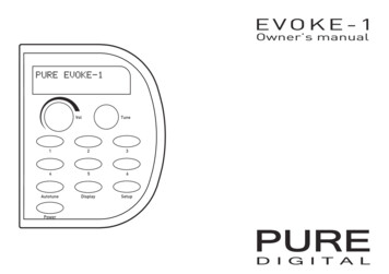
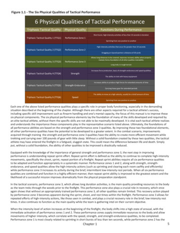
Figure 1-1.Figure 1-2.2.Wavelength of a radio waveComparison of two waves of different frequencyPropagation Methods of Radio Waves.In order to use radio waves as a communications medium, the wavesmust travel from the sending station to the receiving station. Thus,it is important that you understand something of the propagationmethods of radio waves.Electromagnetic waves travel in a straightline unless they are reflected or refracted by some outside force.In the case of radio waves, the basic paths of transmission are theground wave and the sky-wave.Figure 1-3 illustrates thesetransmission paths.a. Three Wave Types.All ground waves fall into one of threewave types. The first type is the direct wave. Direct waves travelalong a line of sight (LOS) path. There must be a clear path betweentwo stations in order to communicate using this transmission path.Communications with aircraft, satellites, and stations within sightof each other generally take place along a direct path. The secondtype of ground wave is similar to the direct wave and is called aground reflected wave.Ground reflected waves also travel instraight lines. The difference between this type and the direct waveis that the ground reflected wave is reflected off the ground at somepoint between the sending and receiving stations.Ground reflectedwaves can sometimes interfere with a direct wave signal if both wavesarrive at the receiving station 180 degrees out of phase.1-3SS0002
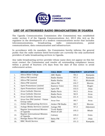
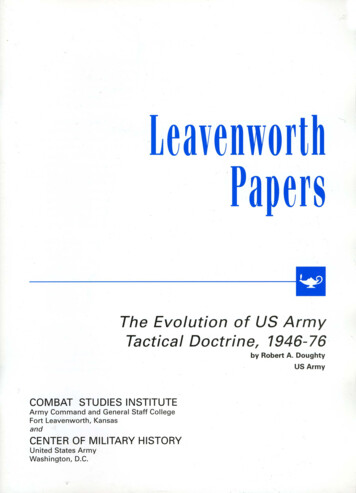
romagnetic properties of the earth's surface and will actuallybend around the curvature of the earth.These are surface waves.You can communicate with stations not in your LOS using systems thattake advantage of these lower frequencies.Figure 1-3.Radio wave transmission pathsb. Sky-Waves.The other type of transmission path is the skywave.Sky-waves are waves that have been transmitted upward andreflected back to the earth by the ionosphere.The ionosphere is aseries of four layers (in daylight hours) of ion concentration in theearth's atmosphere called the D, E, Fl, and F2 regions. Figure 1-4illustrates the ionosphere regions and their approximate heightsabove the earth's surface.The D region of the ionosphere servesonly to attenuate the strength of radio waves and does not provideany useful reflection of the waves. This region fades out at night.The E region also fades at night but provides some reflection ofradio waves during the day. Sky-waves which bounce off the E regioncan provide communications up to about 2,400 kilometers (1,500miles). The F regions of the ionosphere do not fade out at night butthey do combine to form a single region. You can communicate using Fregion sky-waves over distances of over 2,400 kilometers.Thisregion is especially useful at night when the two intervening regions(D and E) have faded. The ionosphere is not constant and, therefore,sky-wave communications are not completely predictable.Theionosphere constantly undergoes variations which are classified asregular or irregular.1-4SS0002
Figure 1-4.Distribution of the ionosphere(1) Regular variations.Regular variations in the ionosphereoccur as a result of the earth being a satellite of the sun androtating about its own axis. These variations are so called becausethe period of variation is fairly well known from previousobservation.You must account for these variations when you planyour communications system.There are four basic types of regularvariations, which are:(a) Daily variations.the earth.These are caused by the rotation of(b) Seasonal variations.tilt of the earth on its axis.(c) 27-day variations.the sun on its axis.These are caused by the seasonalThese are caused by the rotation of1-5SS0002
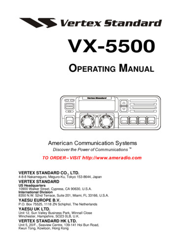
(d) 11-year variations.activity cycle of the sun.Thesearecausedbythesunspot(2) here occur as a result of random events.Because thesevariations occur randomly, you cannot anticipate or plan for them.There are three basic types of irregular variations, which are:(a) Sporadic E.This is caused by the E region becominghighly ionized and blocking out the reflections from the F regions.This can completely blank out sky-wave signals or it can result insignals traveling much further than you would normally expect.(b) Sudden ionospheric disturbance (SID). This is caused bybright solar eruptions.The eruption causes abnormal ionization ofthe D region, absorbing all frequencies above approximately 1megahertz (MHz).This results in receivers seeming to go dead, andit can last for several hours.Since it is associated with the Dregion of the ionosphere, this phenomenon is limited to daylighthours and does not occur after dark.(c) Ionospheric storms.These are caused by meteorologicaldisturbances in the ionosphere. These storms can involve the entireionosphere and can last from several hours to several days.Thisphenomenon can cause low intensity in sky-wave signals and can causea type of random "flutter fading" in sky-wave signals.The range of sky-wave radio transmissions depends largely on thedensity of the ionospheric regions and the frequency of the radiosignal.Because the frequency of a radio wave and its energy levelare proportional, higher levels of ionization must exist in theionosphere in order to reflect the waves back to earth. As a result,there is at any given time a frequency above which radio waves willnot be reflected back to earth.This frequency is the criticalfrequency.The critical frequency is not a fixed value because thelevel of ionization in the ionosphere is constantly changing.Another limiting factor associated with the ionosphere is thecritical angle. The critical angle is that angle of incidence (angleat which the radio wave meets the ionosphere) above which the radiowave will not be reflected, but will pass through the ionosphere andbe lost in space.Two other important terms you should understand when you are dealingwith sky-wave transmissions are skip distance and skip zone.Theskip distance is the distance that a sky-wave travels from itstransmission point to the point where it returns to the earth'ssurface. The skip zone is the area in which no usable1-6SS0002
radio signal can be received because it is shorter than the skipdistance but longer than the ground wave range.Figure 1-5illustrates these concepts.Figure 1-5.Skip zone and skip distanceYou can use a piece of equipment called the AN/TRQ-35(V) IonosphericSounder to determine which frequencies are best for sky-wavetransmission at any time of day or night.3.Useful Frequencies.The number of useful frequencies in radio communications is verylarge, spanning a range of about thirty kilohertz (30 kHz) to about300 Gigahertz (300 GHz), or 30,000 to 300,000,000,000 Hz. Since thetransmission characteristics of radio waves change as the frequencychanges, it is useful to break this wide range of frequencies intosmaller groups called bands.We divide the radio frequency (RF)spectrum into bands of frequencies which have similar transmissioncharacteristics.Table 1-1 shows these frequency bands and theirrespective frequency ranges.1-7SS0002
Most tactical radio sets operate within the medium frequency (MF) toUHF bands.Table 1-1.Frequency sioncharacteristics. The frequency range of the band determines how thewaves propagate and how far they travel. Lower frequency bands (VLFand LF), for example, will travel as surface waves and as sky-waves.Frequencies in the UHF and higher ranges, on the other hand,propagate only as direct waves. The other side of the coin is that,because the wave energy is proportional to the wave frequency, lowerfrequency transmitters must use higher transmission power to get ausable signal strength.Table 1-2 shows the relative ranges andtransmission powers required for some of the frequency bands. Theseranges are approximate and do not take into account such variables asionospheric variations, antenna siting problems, and usable antennaorientation or polarization.Table 1-2.Frequency band characteristics1-8SS0002
4.Forms of Radio Communications.Radio communications can take one of several forms. Messages can bein the form of speech, data, radio teletypewriter (RATT), ortelegraphic code.Let's first consider how a radio set transmitsspeech. The frequency range of normal speech is about 50 Hz to 500Hz.Although these frequencies could be directly converted intoelectromagnetic energy and transmitted, the antenna required would beclose to 5,000 miles long!Thus, you can see that it is notpractical to conduct radio transmissions using this method. Instead,the signal used to transmit speech over radio waves is a combinationof a higher frequency carrier wave and the lower frequency modulatorwave. The sound of speech is converted to electromagnetic energy andthis signal is used to modulate the carrier signal.Using thismethod you can transmit low frequency speech signals using thetransmission characteristics of the higher frequency radio waves.There are two basic types of modulation in radio communications.a. Frequency Modulation.The first type of modulation isfrequency modulation. In FM transmissions, the modulating signal isused to vary the frequency of the carrier wave.The rate at whichthe carrier frequency varies is equal to the frequency of the audiosignal, and the amount of deviation from the carrier frequency isequal to the amplitude of the audio signal. Thus, an FM transmissionconsists of a constant-amplitude wave with frequency varying about acentral rest frequency. Between the transmitter and receiver the FMtransmission may pick up amplitude variations due to outsideelectromagnetic interference. To compensate, most FM receivers use alimiter to exclude these amplitude variations from the receivedsignal.Because of the variances of the carrier frequency, FMtransmissions usually have fairly large bandwidths. For this reason,FM is generally used in VHF and higher frequency bands wherebandwidth is not as significant as in the lower bands.b. Amplitude Modulation.The second type of modulation isamplitude modulation.AM is the variation of RF power output of atransmitter at an audio rate.Simply put, AM is the process ofvarying the amplitude (and thus the output energy) of the carrierwave by superimposing the signal wave on it. In an AM transmission,the rate at which the carrier amplitude varies is equal to thefrequency of the audio signal, and the amount of variation in thecarrier amplitude is equal to the amplitude of the audio signal. superposition of the audio signal produces new RF signals withfrequencies near that of the carrier frequency. For example, assumea 600 kHz carrier is modulated by a .1 kHz audio signal. The two newRF frequencies developed will be 600 kHz /- .1 kHz, or 599.9 kHz and600.1 kHz.These two new frequencies are called sidebands.Thelower frequency is the lower1-9SS0002
sideband and the higher frequency is the upper sideband. Thus for arange of audio frequencies, the frequency range of the sidebandswould be the carrier frequency plus or minus the highest and lowestaudio frequencies.The total space occupied by both sidebands andthe carrier frequency of an AM signal is called a channel, and therange of frequencies is the channel bandwidth.Figures 1-6 and 1-7illustrate the concepts of AM, FM, and sidebands.Figure 1-6.AM and FM wave shapes1-10SS0002
Figure 1-7.AM carrier with sidebandsYou may have guessed from the previous information that the sidebandsof an AM transmission contain duplicate information.In fact, theentire audio signal is contained in each sideband. Because of this,we can eliminate the carrier frequency and one sideband frequencyfrom the transmitted signal and still transmit all the informationneeded for communications.This type of transmission is amplitudemodulation/single sideband (AM/SSB) and is further classified asupper sideband (AM/USB) and lower sideband (AM/LSB).Standard AMtransmission is also called AM double sideband (AM/DSB) transmission.One of the main advantages of an AM/SSB system is that by eliminatingone sideband and the carrier frequency you make room in the frequencyspectrum for extra communications channels.Other advantages of aSSB system are:(1) AM/SSB provides greater reliability than AM/DSB.(2) .(3) AM/SSBsystemsincreasing antenna voltage.provideincreasedoutputwithout(4) AM/SSB systems make it possible to operate a largernumber of radio sets without heterodyne interference (whistles andsqueals) from interfering RF carriers.(5) AM/SSB systems can operate over longer ranges withoutloss of intelligence of the signal due to selective fading.Because of their narrower bandwidth, AM/SSB systems are used in allfrequency ranges, but are especially useful in the HF and lowerfrequency bands.1-11SS0002
5.Basic Transmitter.Now that you have learned the basic theory of radio signals, the nextthing you need to learn about is how a radio set actually converts aninput signal such as your voice into a radio signal that can travelto a distant station, and how the receiver at that station canconvert that signal back into a recognizable voice pattern. We willstart with a basic transmitter.Figure 1-8 illustrates the basiccomponents of a simple continuous wave (CW) transmitter.Thetransmitter consists of a power supply, a keying device, anoscillator, and an antenna.Let's briefly look at each of thesecomponents.Figure 1-8.Block diagram of a simple radio transmittera. Power Supply. The power supply is common to all radio sets.It simply provides electrical power to all the other components inthe radio set.The power supply may consist of transformers andconvertors and may have multiple output voltages.b. Oscillator.The oscillator is the device that actuallyproduces the RF signal to be sent. In the early days of radio, theseoscillators consisted of crystals that vibrated at a certainfrequency when stimulated by an electric current.Some older radiosets still use crystal chips in the oscillator, but most modernradios use some type of electronic appurtenance to perform thisfunction.Most tactical radio sets have oscillators that can betuned to a certain frequency or channel for transmission on thatchannel. An oscillator may also contain1-12SS0002
filters to limit the bandwidthinterference with other radio sets.ofthetransmissiontoavoidc. Antenna.The antenna is nothing more than the device thatconverts RF electrical energy into radio waves that travel to thereceiving station. You will learn more about antennas later in thislesson.d. Keying Device.The keying device is the device you use togenerate a message to be transmitted. In the CW transmitter, the keyserves to interrupt the power to the oscillator and antenna.Thus,when the key is depressed, the power is sent to the oscillator andantenna and a signal is transmitted. When the key is released, poweris interrupted and the signal stops. Using this method you can sendMorse code messages by radio.In order to transmit messages containing something besides Morsecode, you need a transmitter with a few more components. Figure 1-9illustrates a basic radiotelephone transmitter.You can see that amicrophone and modulator have replaced the keying device, and that abuffer and an RF amplifier have been added.Let's look at each ofthese new components briefly.Figure 1-9.Block diagram of a radiotelephone transmittere. Buffer.The buffer is nothing more than a series ofelectronic filters and stabilizers that take the output from theoscillator and ensure that it is as stable as possible. Since the RFsignal from the oscillator is what produces the carrier1-13SS0002
for the radio signal, you can see that it is extremely important forthis signal to be constant and stable.f. Microphone and Modulator.The microphone and modulator inthis transmitter serve the same purpose as the keying device in theCW transmitter previously described. The microphone converts speechinto electrical signals and the modulator converts these signals intoan audio modulating signal.This signal can then be applied to thecarrier to produce the modulated radio wave that can be received andunderstood by a remote receiver.g. RF Amplifier.The RF amplifier is the stage in thetransmitter where the carrier and modulating signals are combined toproduce the radio signal to be transmitted. Depending on the type oftransmitter (AM, FM, etc.), this combination of signals will take oneof the forms we discussed previously in this lesson.The amplifierthen amplifies the combined signal and sends it to the antenna fortransmission.Transmitting a radio signal is useless unless there is a receiversomewhere to receive and understand the message. The receiver, then,is equally as important to radio communications as the transmitter.Figure 1-10 shows a typical radio receiver. As with the transmitter,we will look at each of its components individually.Figure 1-10.Block diagram of a radio receiverh. Receiver Antenna. The antenna on the receiver serves much thesame function that it does on the transmitter.The principaldifference is that the receiver antenna absorbs the radio waves andconverts them to an electronic signal to be used by the receiver.1-14SS0002
i. RF Amplifier.In most transmitters, the energy that istransmitted through the antenna is transmitted in several directions.If the receiving station is more than a small distance from thetransmitter, only a small fraction of the radiated energy of thetransmitter will reach the receiver.You can guess from this thatthe electronic signal produced by the receiver antenna will be verysmall.For this reason, receivers have an RF amplifier attached tothe antenna.The amplifier takes the incoming signal and amplifiesit to a level that can be processed by the receiver's othercomponents.j. Detector.Once the received signal is amplified, the nextstep is to convert the modulated signal back into an audio signalthat will be intelligible to the operator.The detector is thecomponent that does this.The detector, like the modulator in thetransmitter, serves to uncouple or "demodulate" the radio signal. Inan FM receiver, this component is called a discriminator. As in thetransmitter, the exact function of the detector depends on the typeof receiver it serves.k. Audio Amplifier.When the detector separates the audio andcarrier signals, the resulting audio signal is quite small. In orderto raise the audio signal to a usable level (one that can be heard),we use an audio amplifier between the detector and the speaker orheadphone. This amplifier simply amplifies the audio signal so thatit can drive the speaker or headphone and reproduce the sound of theoriginal transmission.Most modern radio sets perform the functions of transmitting andreceiving in the same unit. These radios have a transmitting sectionand a receiving section which generally use the same antenna for bothfunctions, though not simultaneously.Additionally, most radio setsare designed to operate in a particular frequency band and to use aparticular type of modulation.For example, the AN/VRC-12 seriesradio set operates in the VHF band and uses frequency modulation.There are newer radio sets in use today however, that offer much moreflexibility to their users. The AN/PRC-70 series radio, for example,operates in AM, SSB, and FM modes and can transmit and receive inboth HF and VHF bands.One very important thing you must consider when planning radiocommunications is the compatibility of the radios that will becommunicating with each other. There are four basic conditions whichyou must meet if you desire to conduct radio gfrequency,methodofcommunication, and type of modulation. If two radio stations are 200miles apart and one can only transmit up to 100 miles, it cannot beheard by the other station and communications are not possible.Similarly, a VHF radio cannot communicate with an HF radio, nor an AMradio with an FM radio. A CW1-15SS0002
radio could transmit to a RATT radio but the receiving radio wouldnot be able to interpret the signal and would produce no output.6.Antennas.The object of radio communications is to be able to conveyintelligence over long distances without having to use wires to carrythe signal. The component of a radio set that makes this possible isthe antenna.You learned previously that the antenna convertselectronic signals into radio waves in a transmitter and convertsradio waves to electronic signals in a receiver. The antenna, then,is the element that takes the place of thousands of miles of wires intransferring messages from radio station to radio station.It ishelpful in learning about the various types and uses of antennas ifyou first learn some basic concepts and terminology associated withthem.a. Antenna Gain. Antennas come in many different configurationsand some work much better for certain applications than others. Theterm we use to talk about the efficiency of an antenna is antennaGAIN. Antenna gain is simply a measure of an antenna's efficiency attransmitting or receiving certain signals.An antenna that is moreefficient is said to have a higher gain than one that is lessefficient.b. Antenna Polarization.Another term you commonly hearassociated with antennas is polarization. Polarization refers to theorientation of the electromagnetic fields that make up a radio wave.If the fields are perpendicular to the earth's surface, the wave isvertically polarized.If the fields are parallel to the earth'ssurface, the wave is horizontally polarized. Some transmitters, mostnotably satellites, produce fields that constantly change orientationwith respect to the earth's surface. These are circularly polarizedwaves. If an antenna has a better gain in receiving or transmittinga certain type of wave, we say the antenna is polarized in a certaindirection.Thus antennas, as well as radio waves, can behorizontally, vertically, or circularly polarized.You will learnthe particular uses of each type of polarization in an antenna laterin this lesson.c. Directional Antennas.You will learn that some types ofantennas have a higher gain in a certain direction than they do inanother.This is called the directionality of the antenna and isdependent on the type of antenna and its orientation.We callantennas of this type directional antennas. Directional antennas canbe very useful because they transmit and receive in the samedirection. You could use a directional antenna to1-16SS0002
prevent a signal from being intercepted by an enemy on your flank, orto prevent a particularly noisy (RF speaking) industrial area frominterfering with your reception.Another term associated withdirectional antennas is azimuth.The azimuth is the orientation ofthe directional axis of the antenna with respect to true North. Youwill measure azimuth in degrees. Azimuth can be very critical if theantenna you use is highly directional. It is important to know whereyou are in relation to the station you want to communicate with.d.Ground Effect. Except for satellites and aircraft, all antennasare set up on or near the earth's surface.This proximity almostalways has some effect on the performance of the antenna.We callthis phenomena ground effect.If the ground that an antenna isconnected to is a good conductor, it will act like a mirror andreflect RF energy radiated downward by the antenna.If the antennais grounded (electrically attached to the ground) this can
c.Select tactical antennas for specific tactical radio transmission requirements. d.Determine the antenna polarization to obtain optimum communications when using tactical radio sets. e.Recognize and describe the four conditions that must be c