Transcription
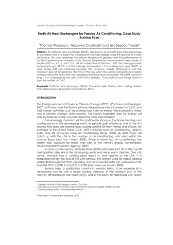
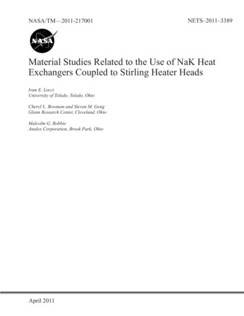
Heat ExchangersHeat exchangers are used to transfer heat between two sources. The exchange cantake place between a process stream and a utility stream (cold water, pressurizedsteam, etc), a process stream and a power source (electric heat), or between twoprocess streams resulting in energy integration and reduction of external heat sources.Typically, a heat exchanger is used with two process streams. However, mutlistreamheat exchangers are sometimes used with energy extensive processes, such as LNGprocessing, to reduce capital cost.The term heat exchanger applies to all equipment used to transfer heat between twostreams. However, the term is commonly used to equipment in which two processstreams exchange heat with each other. In the other hand, the term heater or cooler isused when the exchange occurs between a process stream and a plant service stream.Other terms used to describe heating equipment include: vaporizer and reboiler (forvaporization) and evaporator (for stream concentration). Exchangers can also beclassified as fired (heat source is fuel combustion) and unfired exchangers.There are many types of heat exchangers applied in the process industry. These typesinclude:1.2.3.4.5.6.7.8.Hairpin/Double pipe exchangersShell and tube exchangersPlate and frame exchangersPlate-fin exchangersSpiral heat exchangersAir coolers and condensersDirect contact (quenching towers)Fired heatersThe selection of a heat exchanger depends on many factors including capital andoperating costs, fouling, corrosion tendency, pressure drop, temperature ranges, andsafety issues (tolerance to leakage). Different types of heat exchangers are shown inFigure 42.In process calculations, the main objectives of heat exchanger calculations are todetermine the heat duty (amount of energy to be transferred), temperature changeswithin the exchanger, and pressure drops. Depending on the degree of detailsavailable/needed, the calculations might be simple or thorough.For an exchanger with a hot stream and a cold stream, the heat requirements arecalculated as:(11)Dr. YA Hussain()66
(a) Plat and frame exchanger8(b) Shell and tube exchanger9(c) Air coolers10(d) Double pipe exchanger11()(12)Figure 42. Different types of heat exchangersIn addition, the overall heat transfer equation for the exchanger must be solvedsimultaneously:(13)with being the overall heat transfer coefficient, the heat transfer area, andisthe log-mean temperature difference. Equation (13)(13) is used when simple counteror co-current flows exist. If the flow pattern is more complex (such as the case withmost shell and tube heat exchangers), then a correction factor ( ) term is used and theequation becomes:(14)Depending on the complexity of the chosen model, the information needed inEquation (14) may vary from rough estimation to calculation based on the exchangergeometry.8R. K. Sinnott, John Metcalfe Coulson, and John Francis Richardson, Coulson & Richardson'sChemical engineering Design, vol. 6, 4th ed. (Butterworth-Heinemann, 2005).9Warren McCabe, Julian Smith, and Peter Harriott, Unit Operations of Chemical Engineering (7thedition, 7th ed. (McGraw-Hill Science/Engineering/Math, 2004).10Ernst Schl nder et al., eds., Heat Exchanger Design Handbook (Washington: Hemisphere PublishingCorporation, 1983).11Don Green and Robert Perry, Perry's Chemical Engineers' Handbook, Eighth Edition, 8th ed.(McGraw-Hill Professional, 2007).67
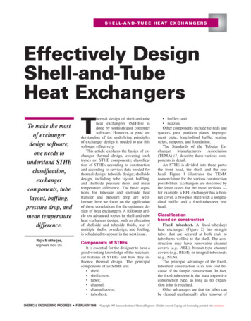
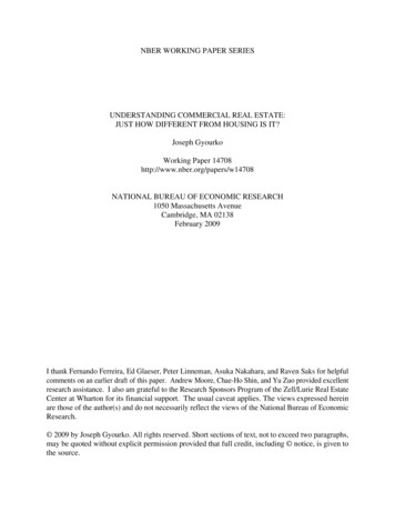
The overall heat transfer coefficient represents the ease with which heat is transferredfrom one medium to another. For example, when heat is being transferred from a hotfluid inside a tube to a cold fluid outside of the tube (as shown in Figure 2), theFigure 43. Heat transfer through tube.12overall heat transfer coefficient is:(15)()withbeing the resistance to heat transfer through each interface (hot fluid-innertube wall, inner tube wall-outer tube wall, and outer tube wall-cold fluid). Theresistance calculation depends on the phase from which heat is being transferred. Forexample, for(transfer at fluid-solid interface) the resistance is given by:(16)(and for)(transfer through solid media), the resistance is given by:(17)()All symbols here take their usual definition. As you can see from Equations (15) to(17), calculatingrequires knowledge of the geometry, materials properties, andflow conditions. Geometry is also needed to calculate the heat transfer area ( ).Material and flow information are needed to calculate the heat transfer coefficients (and ). For example, the heat transfer coefficient in the fluid can be calculated fromgeneral correlations according to fluid flow pattern and phases present. For example,for turbulent flow the heat transfer coefficient can be calculated using the generalcorrelation:(18)12()Yunus A. Çengel, Heat Transfer: A Practical Approach, 2nd ed. (McGraw-Hill, 2002).Dr. YA Hussain68
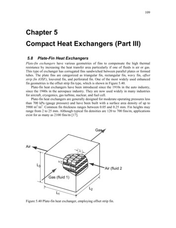
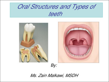
(b) One shell-pass, two tube(c) Two shell-passes, fourpasstube-passes.Figure 44. Different heat exchangers flow patterns.(a) Counter current flowHereis the Reynolds number () andis the Prandtl number (parameters , , , and are constants and depend on the flow.). TheIn addition to affecting flow, the geometry of the exchanger is necessary to calculatethe heat transfer area. The area is calculated based on specifications of the dimensionsof process streams contact area. For example, in a shell and tube exchanger, the pipediameter and length are used for this purpose.The correction factor is used in conjunction with the LMTD to account for thedeviation from the ideal counter-current flow pattern. For example, shell and tubeexchangers where the tubes make more than one pass or when two or more shells areused, as shown in Figure 44. Notice that in Figure 44(b) and (c), part of the flowresembles co-current flow rather than counter current. This flow pattern will cause areduction in the driving force between the streams reducing the amount of heat thatcan be transferred. The LMTD represents the driving force between process streamsand is given by:(19)()whereandare the temperature differences between the two fluids at the twoends (inlet and outlet). The use of the LMTD represents an averaging of the drivingforce since the temperature difference between the two streams changes as it flowsthrough the exchanger, as shown in Figure 45. Theterms in Equation (19)represents the differences at the two ends of the plots in Figure 45. In the countercurrent flow, the driving force is almost constant; while in the counter currentdecreases as the fluids exchange heat. It is important to remember that it is notfeasible for the two curves to cross or reach a pinch point. If the curves cross thismeans that heat transfer will switch direction which is physically impossible (the bestthat can happen is for both streams to reach the same temperature).69
The LMTD can be problematic in cases where or when either of thetemperature differences is zero. While such cases are physically feasible, numericalcalculations of Equation (19) are not possible. In such cases, other averagingtechniques can be applied. For example, the arithmetic meanis given by:(20)can give good approximation oflargely as the ratio departs from 1.when theratios are closer to 1 but deviatesAs mentioned earlier, the correction factor is used to correct the LMTD from the idealcounter current flow. The magnitude of the correction depends on the temperaturedifferences and the flow pattern. Two ratios are used to represent the temperaturedifference effect as follows:(21)and:(22)( ̇)( ̇)Figure 45. Temperature distribution inside counter and co-current (parallel) flow exchangers13.13Schl nder et al., Heat Exchanger Design Handbook.Dr. YA Hussain70
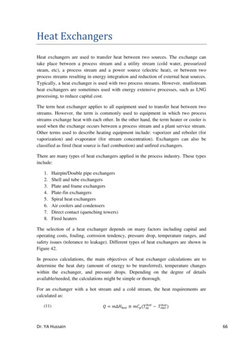
Calculations of the correction factors is then obtained from charts similar to that inFigure 46 for each the different flow patterns. Notice that the correction factor has alimiting value of one which occurs at low and values.Pressure Drop CalculationsAs the fluid passes through the exchanger its pressure will drop. Pressure drop in theFigure 47. Main parts of the shell and tube heat exchanger.15Figure 46. Correction factor chart for one-shell and multiple tube passes exchanger.14tube side of heat exchangers can be calculated using correlations for pipeline pressuredrop. Correlations such as Beggs-Brill can be used for this purpose. In addition, thepressure drop can be related directly to the flow rate through a flow rate dependentcorrelation. In the first case, information is needed on the geometry of the exchangerin order to calculate the flow regime and friction factors. The flow rate correlations donot require information about the geometry but lumps the heat exchanger effect onpressure in one parameter as follows:(23)14(Çengel, Heat Transfer.71)()
Shell & Tube ExchangersThe most commonly used unfired heat exchangers in the chemical-process plants arethe shell and tube exchangers. These exchangers are made of a shell housing smallertubes. One fluid is made to pass through the tubes (tube side) and the other is passedthrough the shell (shell side).As shown in Figure 47, the shell and tube heat exchanger consists of the shell, whichis a large vessel with one or more inlet and one or more outlet nozzles. Inside theshell, baffles are typically installed which help in holding the tubes and directing theshell fluid flow to some extent. The locations of the nozzles and the orientation of thebaffles largely affect the flow pattern of the shell side. The shell fluid can be passedthrough the shell only once (single pass) or it can be passed multiple times (multipass).Inside the shell, large number of tubes (sometimes several hundred) is placed. Again,the tubes may pass through the shell onlyonce (single pass) or multiple times (multipass).The diameter (inside and outside) andlength of the tubes determine the overallheat transfer area. The pattern (the way thetubes are arranged, see Figure 48) and thepitch (the center-to-center distance betweenthe tubes) determine the number of heattubes that can fit in the shell and affects theFigure 49. Fineed tube.16pressure drop. The tubes can be finned to increase the heat transfer area, but this willrequire a larger pitch, thus reducing the number of tubes. Fins are characterized bytheir height (or diameter), numbers, and efficiency (ability of the fin to transfer theheat).Figure 48. Triangular (left) and square (right) pitch.1516Ibid.Green and Perry, Perry's Chemical Engineers' Handbook, Eighth Edition.Dr. YA Hussain72
Another part of shell and tube exchangers that affect it performance is the baffles.These are metal sheets used inside the shell for purposes of heat transfer (if heattransfer considerations are not important, baffles are replaced with tube supports tohold the tubes). A number of baffle configurations are available; some are shown inFigure 51. Important parameters for baffle design are its cut (percentage of shelldiameter not covered by baffle), baffle spacing, and clearances left between the baffleand shell, and between the baffle and the tubes.Finally, many of the features and designations of shell and tube exchangers have beenstandardized by the Tubular Exchanger Manufacturers Association (TEMA). Thisorganization has put standard codes for the configurations of heat exchangers asshown in Figure 51 and as described in Perry's Handbook (section 11). The standardscover codes for front end, shell, and rear ends of the exchangers. These codes can beused to designating exchangers. For example, a fixed-tube sheet exchanger havingstationary and rear heads integral with tube sheets, single-pass shell, 432 mm (17 in)inside diameter with tubes 4.9 m (16 ft) long. SIZE 17–192 TYPE CEN. Here, the 17is the shell inside diameter, the 192 is the tube length in inches, and the CEN refers tothe front, shell, and rear types from Figure 51. TEMA also provides standard(a) Single(b) DoubleFigure 50. Different baffle configurations.17(c) Triplespecification sheets for the different types of heat exchangers. TEMA sheets are usedby many process engineers to identify their exchangers and to communicate with heatexchanger manufacturers. A typical shell and tube exchanger TEMA sheet is shownin Figure 52.Heat Exchangers in Aspen PlusUnder the heat exchangers library in Aspen Plus, there are four modules: the heater,heat exchanger, multistream exchanger, and heat flux. The first three modulescorrespond to the heat exchanger functionalities mentioned in page 66. The heat fluxmodule is used to perform heat transfer calculations based on the use input. It does nothave flowsheet connectivity, and used as a standalone module.The Heater Block17Ibid.73
Figure 51. Shell and tube heat exchanger TEMA designations.18The heater block is used for simple temperature or phase change applications wheredetails of the heat transfer calculations are not important. The block can also be usedas a pressure changer when the pressure drop is known. The heater block takes one ormore inlet and one outlet material streams (plus optional water decant stream). It alsotakes an (optional) heat input and heat output streams.B118Ibid.Dr. YA Hussain74Q
Heat Exchanger Specification 5354555657Company: Jordan University of Science & TechnologyLocation: Irbid, JordanService of Unit:Our Reference:Item No.:Your Reference:Date: 20/3/2011Rev No.: 1Job No.:P1-43Size35 /288 inTypeAELHorConnected in1parallel2seriesSurf/unit(eff.)10109.7 ft2Shells/unit2Surf/shell (eff.)5054.8ft2PERFORMANCE OF ONE UNITFluid allocationShell SideTube SideFluid nameFluid quantity, Totallb/h899984824984Vapor Noncondensablelb/h00Temperature (In/Out)Dew / Bubble pointDensity (Vap / Liq)ViscosityMolecular w t, VapMolecular w t, NCSpecific heatThermal conductivityLatent heatPressure (abs)VelocityPressure drop, allow ./calc.Fouling resist. (min)Heat exchange
The Heat Exchanger Block. The heat exchanger block is used when two process streams are to exchange heat based on Equations (11) – (14). The exchanger takes