Transcription
UFT Series Joint SimulatorOperations ManualPO Box 16460, Portland, OR 97292-0460 800-852-1368 Fax 800-582-9015www.aimco-global.com
ContentsPageNumber1. Operations Instructions for the UFT-S10 and UFT-S1612. Breakdown of the UFT-S Joint Simulator23. Breakdown of the UFT-S10 Joint Simulator34. Breakdown of the UFT-S16 Joint Simulator45. Operations Instructions for the UFT-6, UFT-10, UFT-16 and UFT-2456. Breakdown of the UFT-BC Joint Simulator (Front and Top Views)67. Breakdown of the UFT-6 Joint Simulator78. Breakdown of the UFT-10 Joint Simulator89. Breakdown of the UFT-16 Joint Simulator910. Breakdown of the UFT-24 Joint Simulator1011. Maintenance1112. Certification of the UFT Joint Simulator1213. List of Hexagon Head Bolts13
Operations InstructionsUFT-S10 and UFT-S16These testers are capable of simulating four different joints: A, B, C, and D (hard, medium-hard, medium-soft, andsoft, respectively).A Joint:C and D valves closed (clockwise) and the A joint sleeve installed between the Plunger Bushingand the Spindle Nut.B Joint:C and D valves closed (clockwise) and remove the A joint sleeve.C Joint:Open the C valve under the side cylinder one turn (counter-clockwise). The D valve remainsclosed.D Joint:Open both the C and D valves (one turn).Changing Bolt KitsTo change the bolt:1. Remove the test bolt.2. Remove the Spacer and Plunger Bushing.3. Remove the Allen Head Bolt that holds the Spindle Nut. This is located on the side of the tester by the D valvelever.4. Remove the Spindle Nut.5. Install the new Spindle Nut.6. Install the Allen Head Bolt back through the Spindle Nut.7. Install the Plunger Bushing, Spacer, and new bolt.-1-
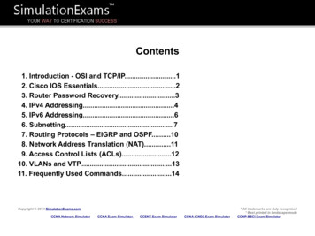
Breakdown of the UFT-S Joint SimulatorTop View of UFT-S Joint SimulatorSide View of UFT-S Joint Simulator-2-
Breakdown of the UFT-S10 Joint -013-0962-644-0966-100-0DescriptionBaseSetting PlateRear PlateCylinderPlungerPilot PinPlunger BushingCylinder BushingPistonOil PlugValveSpindle Nut (M10)StopperBushing (M10)Piston Spring GuideFront PlateOil CasingPistonOil Casing CoverConnecting ScrewSupporter Ring (3.0 x 5.0 x 1)Back-up Ring (4.2 x 6 x 1)Back-up Ring (P7)Back-up Ring (P16)Back-up Ring (P24)Back-up Ring (P44)Allen Head Bolt (M3 x 50)Allen Head Bolt (M8 x 15)Allen Head Bolt (M8 x 30)Allen Head Bolt (M12 x 20)Hexagon Round Head Bolt (M4 x 8)Hexagonal Bolt (M10 x 35) (UFT)Hexagon Nut (1-M3)Spring Washer (2-8S)Spring Washer (2-12S)Belleville Spring (42 x 14.3 x 2.5)Allen Head Plug 93-0990-998-0990-972-0Allen Head Plug (3/8)Roll Pin (2.5 x 12)Spacer (13 x 4.2 x1.5)Spacer (22 x 10.5 x 3) (H)Adjusting Spacer (53 x 48.2 xT)Spring (21 x 65)Spring (33 x 65)O-Ring (P6)O-Ring (P15)O-Ring (P24)O-Ring (P44)O-Ring (SNS-2) (NOK)O-Ring (P9)O-Ring (SNS-10)O-Ring (SNS-22)O-Ring (SNS-70)O-Ring (SNS-112)O-Ring (SNS-4) (NOK)112116661112211112M8 71-0975-551-0990-906-0990-919-0Bushing (M8)Plunger Bushing (M8)Spindle Nut (M8)Hexagonal Bolt (M8 x 32) (UFT)Spacer (18 x 8.5 x 2.5) (H)O-Ring (SNS-8)O-Ring (SNS-22)1111111M6 70-0975-550-0990-904-0990-919-0Bushing (M6)Plunger Bushing (M6)Spindle Nut (M6)Hexagonal Bolt (M6 x 30) (UFT)Spacer (14 x 6.5 x 2) (H)O-Ring (SNS-6)O-Ring (SNS-22)1111111-3-DescriptionQty.
Breakdown of the UFT-S16 Joint 14-0966-100-0966-102-0DescriptionSetting StandSetting PlateRear PlateCylinderPlungerPilot PinPlunger Bushing (M16)Cylinder BushingPistonSpacerValveSpindle NutStopperBushing (M16)Piston Spring GuideFront PlateOil CasingPiston (large)Oil Casing CoverConnecting ScrewBack-up Ring (4.2 x 6 x 1)Back-up Ring (P32)Back-up Ring (P70)Back-up Ring (P12)Back-up Ring (P16)Allen Head Bolt (M3 x 50)Allen Head Bolt (M10 x 20)Allen Head Bolt (M10 x 35)Allen Head Bolt (M10 x 45)Allen Head Bolt (M14 x 30)Hexagon Round Head Bolt (M4 x 6)Hexagonal Bolt (M16 x 50) (UFT)Hexagon Nut (1-M3)Spring Washer (2-10S)Spring Washer (2-14S)Allen Head Plug (1/8)Allen Head Plug 990-972-0990-996-0990-999-0Roll Pin (4 x 16)Spacer (13 x 4.2 x 1.5)Spacer (35 x 16.5 x 3) (H)Adjusting Spacer (68 x 30 x T)Spring (23 x 75) (4.0)Spring (37.5 x 75) (7.0)Spring (64 x 75) (12.0)O-Ring (P11)O-Ring (P15)O-Ring (P22)O-Ring (P32)O-Ring (P70)O-Ring (JW1530-15)O-Ring (SNS-16)O-Ring (SNS-46)O-Ring (SNS-3) (NOK)O-Ring (SNS-4) (NOK)O-Ring (SNS-100)O-Ring -912-1946-974-0975-556-0990-912-0990-937-0Plunger Bushing (M14)Spindle Nut (M14) (S16)Bushing (M14)Hexagonal Bolt (M14 x 50) (UFT)Spacer (30 x 14.5 x 3) (H)O-Ring (SNS-14)O-Ring 0975-555-0990-911-0990-937-0Plunger Bushing (M12)Spindle Nut (M12) (S16)Bushing (M12)Hexagonal Bolt (M12 x 45) (UFT)Spacer (26 x 12.5 x 3) (H)O-Ring (SNS-12)O-Ring (SNS-46)1111111M14 Type57585960616364M12 Type66676869707374-4-DescriptionQty.
Operations InstructionsUFT-6, UFT-10, UFT-16 and UFT-24Warning1. Always operate test bolt within specified torque range.2. Always secure joint simulator before use.Operation Cautions1. Never change joints without loosening the test bolt.2. Check the test bolt every 50,000 cycles.3. Double-check all bolts after changing joints and bolt sizes.4. Never use sloppy sockets or extensions.5. Always use Power Driver Sockets per ANSI B107.2.Operation InstructionsUFT-6, UFT-10, UFT-16 and UFT-24There are two joints on these models: A “B” joint (medium-hard) and a “C” joint (medium-soft). To change thesejoints, simply turn the silver knob on the front of the tester clockwise until it stops for the “B” joint and counterclockwise until it stops for the “C” joint.Changing Bolt KitsUFT-10, UFT-16 and UFT-241. Each bolt kit has certain springs that go with them. Please consult the chart below to match the right spring withthe size of bolt that you are using.2. To change bolts:a) Remove the test bolt and Plunger Bushing.b) On the UFT-10 and UFT-16, remove the two Allen Head Bolts from the Spindle Nut located on the back ofthe testers. Insert the new Spindle Nut and re-install the Allen Head Bolts.c) Install the new bolt and Plunger Bushing.d) Remove the Cylinder Liner Casing Cover and change out the springs. Reinstall the Cylinder Liner CasingCover.ModelUFT-10UFT-16UFT-24Bolt SizeM6M8M10M12M14M16M18M20M20M24M24Spring Size Installed Into the Chamberand the Quantity Used48.5 x 12051 x 12051 x 12049 x 12049 x 12049 x 12059 x 11559 x 11535.5 x 10559 x 11535 x 6.6)(11.0)(7.0)1 pc.1 pc.1 pc.2 pcs.2 pcs.2 pcs.3 pcs.3 pcs.3 pcs.3 pcs.3 pcs.
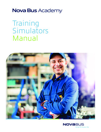
Breakdown of the UFT-BC Joint SimulatorFront ViewTop View-6-
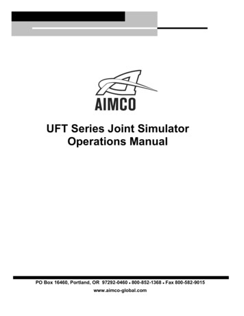
Breakdown of the UFT-6 Joint 973-210-0DescriptionSetting StandCylinderPlungerPilot PinSetting Screw for Pressure SensorPlunger Bushing (M6)Spindle Nut (M6)Cylinder LinerPistonRetainerRetainer BushingValve LeverValveValve Wheel Nut FlangeSpring Holder SpacerSupport Ring (42 x 6 x 1)Back-up Ring (P9)Back-up Ring (P6)Back-up Ring (P28)Hexagon Bolt (M6 x 18) (UFT)Spacer (14 x 6.5 x 2) (H)Allen Head Bolt (M4 x 10)Allen Head Bolt (M5 x 8)Allen Head Bolt (M6 x 45)Allen Head Bolt (M8 x 25)Allen Flush Head Screw (M3 x 6)Allen Head Plug (NPT1/16)Roll Pin (2 x 8)Roll Pin (2 x 10)Roll Pin (3 x 30)Roll Pin (4 x y.Spring (52 x 80) (9.0)O-Ring (P6)O-Ring (P9)O-Ring (P28)O-Ring (SNS-14)O-Ring (SNS-18)O-Ring (SNS-24)O-Ring (SNS-38)O-Ring (SNS-4)Allen Head Plug (3/8)Test Socket (10 x 3/8)Spacer (14 x 6.5 x 2) (H)121111111111M5 990-912-050990-917-0Plunger Bushing (M5)Spindle Nut (M5)Hexagon Bolt (M5 x 17) (UFT)Spacer (12 x 5.5 x 2) (H)O-Ring (SNS-14)O-Ring (SNS-24)111111M4 Type515253545556Plunger Bushing (M4)Spindle Nut (M4)Hexagon Bolt (M4 x 15) (UFT)Spacer (10 x 4.5 x 2) (H)O-Ring (SNS-14)O-Ring 8-0990-912-0990-917-0
Breakdown of the UFT-10 Joint 0-0973-114-0973-126-0DescriptionSetting StandSetting PlateCylinderPlungerPilot PinPressure Gauge Stand ScrewCylinder BushingPlunger Bushing (M10)Spindle Nut (M10)Cylinder LinerPistonCylinder Liner CasingSpring SetterSpring Setter BushingCylinder Liner Casing CoverSelecting DialValve BodyValveBackup Ring (4.2 x 6 x 1)Backup Ring (P9)Backup Ring (P14)Backup Ring (P24)Backup Ring (P48A)Allen Head Bolt (M6 x 14)Allen Head Bolt (M6 x 30)Allen Head Bolt (M8 x 20)Hexagon Round Head Bolt (M6 x 25)Hexagonal Bolt (M10 x 35) (UFT)Spacer (22 x 10.5 x 3) (H)Allen Head Plug (NPT1/6)Roll Pin (3 x 14)Roll Pin (3 x 24-0990-972-0966-102-0Spring (51 x 120) (10.0)Inner Snap Ring (IRTW-12)O-Ring (P9)O-Ring (P14)O-Ring (P24)O-Ring (P48A)O-Ring (SNS-6)O-Ring (SNS-7)O-Ring (SNS-10)O-Ring (SNS-15)O-Ring (SNS-18)O-Ring (SNS-30)O-Ring (SNS-4) (NOK)Allen Head Plug (3/8)M8 -551-0976-766-0990-906-0990-924-0Plunger Bushing (M8)Spindle Nut (M8)Hexagonal Bolt (M8 x 32) (UFT)Spacer (18 x 8.5 x 2.5) (H)Spring (51 x 120) (9.5)O-Ring (SNS-8)O-Ring (SNS-30)11M6 -550-0976-765-0990-904-0990-924-0Plunger Bushing (M6)Spindle Nut (M6)Hexagonal Bolt (M6 x 30) (UFT)Spacer (14 x 6.5 x 2) (H)Spring (48.5 x 120) (8.5)O-Ring (SNS-6)O-Ring 1111-8-DescriptionQty.11211111321111111111
Breakdown of the UFT-16 Joint tionSetting StandSetting PlateCylinderPlungerPilot PinPressure Gauge Stand ScrewCylinder BushingPlunger Bushing (M16)Spindle Nut (M16)Cylinder LinerPistonCylinder Liner CasingSpring SetterSpring Setter BushingCylinder Liner Casing CoverBushingSelecting DialValve BodyValveSeparatorBack-up Ring (4.2 x 6 x 1)Back-up Ring (P9)Back-up Ring (P14)Back-up Ring (P32)Back-up Ring (P70)Allen Head Bolt (M6 x 14)Allen Head Bolt (M6 x 35)Allen Head Bolt (M8 x 20)Allen Head Bolt (M10 x 25)Hexagon Round Head Bolt (M6 x 25)Hexagonal Bolt (M16 x 50) (UFT)Spacer (34 x 16.5 x 3) (H)Allen Head Plug (NPT1/6)Roll Pin (3 x 923-0990-937-0990-972-0966-102-0Roll Pin (4 x 16)Spring (49.5 x 120) (9.5)Inner Snap Ring (ITRW-12)O-Ring (P9)O-Ring (P14)O-Ring (P32)O-Ring (P70)O-Ring (SNS-6)O-Ring (SNS-9)O-Ring (SNS-10)O-Ring (SNS-15)O-Ring (SNS-16)O-Ring (SNS-26)O-Ring (SNS-46)O-Ring (SNS-4) (NOK)Allen Head Plug 5-556-0976-763-0990-912-0990-937-0Plunger Bushing (M14)Spindle Nut (M14)Hexagonal Bolt (M14 x 50) (UFT)Spacer (30 x 14.5 x 3) (H)Spring (49 x 120) (9.0)O-Ring (SNS-14)O-Ring 0976-763-0990-911-0990-937-0Plunger Bushing (M12)Spindle Nut (M12)Hexagonal Bolt (M12 x 45) (UFT)Spacer (26 x 12.5 x 3) (H)Spring (49 x 120) (9.0)O-Ring (SNS-12)O-Ring (SNS-461111211M14 Type51525353-1545556DescriptionQty.M12 Type58596060-1616263-9-
Breakdown of the UFT-24 Joint Simulator31 946-978-0966-100-0DescriptionSetting StandSetting PlateCylinder Rear PlateCylinderPlungerPilot PinPlunger Bushing (M24)Spindle Spacer (53 x 24.5 x 5) (H)Spindle Nut (M24)Socket PinSocket PlateSocketSocket BushingAir Inlet BushingAir Inlet Bushing (B)BushingValve BushingValve BodyValve SpindleValveSelecting DialCylinder LinerPistonCylinder LinerPistonLiner CasingPiston RodLiner Casing SetterAllen Head Plug (1/4)Back-up Ring (P22)Back-up Ring (P25)Back-up Ring (P50)Back-up Ring (P115)Back-up Ring (6.1 x 8 x 1)Allen Head Bolt (M6 x 12)Allen Head Bolt (M6 x 169)Allen Head Bolt (M8 x 30)Allen Head Bolt (M8 x 45)Allen Head Bolt (M10 x 35)Allen Head Bolt (M12 x 30)Hexagon Head Bolt (M24 x 90) (UFT)Allen Head Plug 990-929-0990-991-0878-877-1Roll Pin (3 x 12)Roll Pin (3 x 24)Roll Pin (3 x 30)Roll Pin (5 x 24)Spring (59 x 115) (11.0)Spring (35 x 105) (7.0)Outer Snap Ring (E4)O-Ring (P14)O-Ring (P22)O-Ring (P25)O-Ring (P50)O-Ring (P115)O-Ring (SNS-6)O-Ring (SNS-22)O-Ring (SNS-24)O-Ring (SNS-30)O-Ring (SNS-36)O-Ring (SNS-67)Test Socket (3/4SQ x 36) (M24)1111331413111123111M20 4-1Plunger Bushing (M20)Spindle Spacer (44 x 20.5 x 4) (H)Spindle Nut (M20)Hexagon Head Bolt (M20 x 85) (UFT)Spring (35.5 x 10⁵) (6.5)O-Ring (SNS-20)O-Ring (SNS-36)O-Ring (SNS-67)Test Socket (3/4SQ x 30) (M20)111131111M18 -792-0990-916-0990-929-0990-991-0878-871-1Plunger Bushing (M18)Spindle Spacer (40 x 18.5 x 4) (H)Spindle Nut (M18)Hexagon Head Bolt (M18 x 80) (UFT)O-Ring (SNS-18)O-Ring (SNS-36)O-Ring (SNS-67)Test Socket (3/4SQ x 27) (M18)11111111- 10 -DescriptionQty.
Maintenance1. Inspect the Bolt and Spindle Nut every 50,000 cycles.2. Should the Plunger not come back up to the top of the Cylinder, then the tester is low on fluid. To fill the testerwith fluid, the tester must be level. Remove the two oil filler plugs from the plunger.Pull the plunger back up to the top of the cylinder.While holding the plunger up, fill the tester up through the filler holes with Dextron II.Reinstall the oil filler plugs.3. If the Plunger continues to stay down, the tester has a damaged seal and must be repaired. After the damagedparts are replaced, follow the same fill procedures as above.- 11 -
Certification of the UFT Joint SimulatorThe UFT tester should be certified every 5,000 cycles.Certification Procedures1. On the chart below, find the UFT model you are certifying.2. Next, find the bolt size.3. With a torque wrench, tighten to the recommended snug torque.4. Turn the torque wrench the number of degrees recommended from snug for each joint. The torque reading shouldbe the same as shown on the chart.5. If the readings do not match, the Test Bolt might be worn. Replace the Test Bolt and re-certify the tester. If thetester still does not match the chart, check the fluid level and/or all O-Rings and Supporter Rings for wear.Torque Values for Certifying TesterModelUFT-S10UFT-S16Bolt SizeSnug PointTorqueB Joint at 60 fromSnugft. lbs.Nmft. 166.157.3-85.977.6-116.460 from SnugUFT-6UFT-10UFT-16UFT-24UFT-33C Joint at 180 from D Joint at 180 fromSnugSnugft. lbs.Nm180 from 60M30- 12 -ft. lbs.Nm
List of Hexagon Head BoltsFor UFT Joint SimulatorsMODELPART NUMBERBOLT M6 x M6 x 30M8 x 32M10 x 35UFT-10UFT-10UFT-10946-970-0946-971-0946-972-0M6 x 30M8 x 32M10 x M12 x 45M14 x 50M16 x 50UFT-16UFT-16UFT-16946-973-0946-974-0946-975-0M12 x 45M14 x 50M16 x 80UFT-24UFT-24UFT-24946-976-0946-977-0946-978-0M18 x 80M20 x 85M24 x 90- 13 -
AIMCO CORPORATE HEADQUARTERS10000 SE Pine StreetPortland, Oregon 97216Phone: (503) 254–6600Toll Free: 1-800-852-1368AIMCO CORPORATION DE MEXICO SA DE CVAve. Cristobal Colon 14529Chihuahua, Chihuahua. 31125MexicoPhone: (01-614) 380-1010Fax: (01-614) 380-1019LIT-MAN350 Rev. 07/2020Printed in USA 2020 AIMCO
b) On the UFT-10 and UFT-16, remove the two Allen Head Bolts from the Spindle Nut located on the back of the testers. Insert the new Spindle Nut and re -install the Allen Head Bolts. c) Install the new bolt and Plunger Bushing. d) Remove the Cylinder Liner Casing Cover and change out the springs. Reinstall the Cylinder Liner Casing Cover.