Transcription
Wireless SOHOInstallation & Operation ManualCopyright 2010 LG-Ericsson Co., Ltd. All Rights ReservedThis material is copyrighted by LG-Ericsson Co., Ltd. Any unauthorized reproductions, use or disclosure of thismaterial, or any part thereof, is strictly prohibited and is a violation of Copyright Laws. LG-Ericsson reserves theright to make changes in specifications at any time without notice. The information furnished by LG-Ericsson inthis material is believed to be accurate and reliable, but is not warranted to be true in all cases.All other brand and product names are trademarks or registered trademarks of their respective companies.Special notes for operation in New ZealandLWS (LG-Ericsson Wireless SOHO)Installation & Operation ManualThe grant of a Telepermit for any item of terminal equipment indicates only that Telecom has accepted thatthe item complies with the minimum conditions for connection to its network. It indicates no endorsement ofthe product by Telecom, nor does it provide any sort of warranty. Above all, it provides no assurance thatany item will work correctly in all respects with another item of Telepermitted equipment of a different makeor model, nor does it imply that any product is compatible with all of Telecoms network services.Telepermitted equipment only may be connected to this unit’s SLT port. The SLT port is not specificallydesigned for 3-wire-connected equipment, 3-wire-connected equipment might not respond to incomingringing when attached to this port.Under power fail conditions, this telephone system may not operate. Please ensure that a separatetelephone, not dependent on local power, is available for emergency use.The caller’s telephone numbers which are displayed and stored in this equipment include the callers areacode plus the toll prefix “0”. When calling-back to a local number caller using the stored CLI, the “0” andarea code will be used, which may incur a toll charge, depending on your toll carrier. If a charge for localcalls is unacceptable, only the 7 digits of the local number should be dialled.The Caller Display receiver operates correctly in conjunction with Telecom’s ringing cadences DA1 (normalcadence) DA2 (unused cadence) and DA4 (FaxAbility cadence). It does not operate in conjunction withringing cadence DA3 (unused cadence).
Wireless SOHOInstallation & Operation ManualWireless SOHOInstallation and Operation ManualRevision HistoryISSUEDATEContents of Changes1.01.1Feb. 2010March 20101.2Juluy 2010Initial releaseRevised the text of Menu on LCD and corrected misspelling. Andadded to Special note for New Zealand.Change the new CI (LG-Ericsson)Table of ContentsSPECIAL NOTES FOR OPERATION IN NEW ZEALAND . IG1 INTRODUCTION. 1G1.1 Manual Usage . 1G1.2 Package Contents . 1G1.3 Configuration . 2G1.4 System Capability. 3G1.4.1 Description . 3G1.5 Important Safety Information. 4G1.5.1 Installation and Environment . 4G1.5.2 Electrical Considerations . 4G1.5.3 Precaution . 5G1.5.4 Caution. 5G2 INSTALLATION . 6G2.1 Pre-Installation . 6G2.1.1 Safety Installation Instructions . 6G2.2 Battery Installation . 7G2.2.1 GDC-400H Handset Battery Installation . 7G2.2.2 GDC-450H Handset Battery Installation . 8G2.3 LWS-BS, Handset and Peripheral Connections . 10G2.3.1 FAX Connection. 11G2.3.2 AC/DC Adapter Connection. 11G2.3.3 LWS-WK Connection . 12G2.3.4 Wireless Handset Connection . 12G2.3.5 Foot Stand Connection (the LWS-BS and LWS-WK) . 13G2.4 Hardware Installation . 15G2.4.1 Wall Mount of the LWS-BS or the LWS-WK. 15G2.5 Component Description . 16G2.5.1 LWS-BS Description . 16G2.5.2 LWS-WK Description . 17G2.5.3 Wireless Handset Description . 18G2.6 Hardware Initialization. 19G2.6.1 LWS-BS and LWS-WK . 19G2.6.2 Wireless Handset. 19Gi
Wireless SOHOInstallation and Operation ManualWireless SOHOInstallation and Operation Manual2.7 Display . 19G3.10.3 Automatic Hold . 40G2.7.1 LCD Specification . 19G2.7.2 LCD Display . 20G3.11 CID Blacklist. 40G2.8 Keypad Description . 22G2.8.1 LWS-BS . 22G2.8.2 LWS-WK . 22G2.8.3 GDC-400H/450H Wireless Handset . 23G2.9 LED Operation Description . 25G2.9.1 LWS-BS and Wireless Keyset . 25G2.10 Configuration . 26G3.12 Allowed/Denied Number . 41G3.13 MOH (Music-On-Hold) . 41G3.14 Speed Dial . 42G3.14.1 Display Security . 42G3.14.2 Station Speed Dial . 42G3.14.3 System Speed Dial . 43G3.15 VSF Integrated Auto Attendant/Voice Mail . 44G2.10.1 Country code . 26G2.10.2 LWS-BS Date and Time . 27G3.15.1 VSF . 44G3.15.2 Auto Attendant . 44G3.15.3 VSF Voice Mail . 45G2.11 Terminal Registration and Termination . 27G3.16 Wake-Up Alarm . 49G2.11.1 Registering the GDC-400H/450H / LWS-WK to LWS-BS . 27G2.11.2 Terminating a Registration. 29G3.17 Intercom Call (ICM Call) . 50G2.12 Menu Trees. 30G2.12.1 LWS-BS Menus . 30G2.12.2 LWS-WK Menus . 30G2.13 System Capacities . 31G3 OPERATION INSTRUCTIONS . 32G3.1 Call Forward . 32G3.2 Call Pick-up . 33G3.18 Intercom Call Hold . 51G3.19 Line Ring Assignment . 51G3.20 Night/Weekend mode . 52G3.21 Call Log Display. 52G3.22 Mute . 53G3.23 Tel/Fax Line . 53G3.24 Feature Code for LWS-BS . 54G3.25 Feature Code for LWS-WK . 55G3.2.1 Directed Call Pick-Up . 33G3.2.2 Group Call Pick-Up . 33G4 USEFUL INFORMATION . 56G3.3 Call Transfer . 34G4.1 Trouble shooting . 56G3.4 Call Waiting/Camp-On . 35G3.5 LINE Access . 35G3.6 Three-Party Voice Conference . 36G3.7 Directory . 37G3.8 DND(Do Not Disturb) . 37G3.9 Headset Compatibility . 38G3.10 Hold. 39G3.10.1 Hold. 39G3.10.2 Hold Recall. 40Giiiii
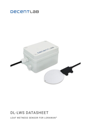
Wireless SOHOInstallation and Operation ManualWireless SOHOInstallation and Operation ManualThe LWS-WK includes one (1) wireless keyset, one (1) AC/DC power adapter, one (1) AC power cord, andone (1) ‘Quick User Guide’. Verify that all parts shown below were provided in the package.1 INTRODUCTIONThis Installation & Operation Manual is designed to provide general system features and operatinginstructions for the LWS (LG-Ericsson Wireless SOHO) System.This wireless telephone system is compliant to the Digital Enhanced Cordless Telecommunication (DECT)specification, using carrier frequencies from 1.88GHz to 1.9GHz. It uses Time Division Multiple Access(TDMA) technology, providing security and protection from eavesdropping. The system utilises duplexcommunication between each handset or keyset via the LWS-BS (base).LWS-WK(Wireless Terminal)Power AdapterAC power cordQuick User GuideFigure 1.2-2 LWS-WK Package Contents1.1 Manual Usage1.3 ConfigurationThis document provides general information about the installation, description and operation of the LWSsystem. While every effort has been made to ensure the accuracy of this information, LG-Ericsson takesno responsibility for the accuracy or interpretations thereof.The following image depicts a sample configuration using LWS-BS system and wireless phones, LWS-WKand GDC-400H/450H.This section is a functional listing of features with the description and operation of each.The structure is divided into 3 parts as listed:z Description: explains the nature of the feature.z Operation: describes how to use the feature.z NOTE: explains any requirements or constraints of the feature related to its configuration.1.2 Package ContentsThe LWS-BS includes one (1) base station, one (1) AC/DC power adapter, one (1) AC power cord, one(1)antenna with rubber ring, three (3) line cords, one (1) ‘Quick User Guide’ and one (1) CD manual.Please verify that all parts shown below were provided in the package.LWS-BS(LWS-BS Unit with Foot)Quick User GuidePower AdapterAC power cordAntennaManual (CD)Figure 1.2-1 LWS-BS Package Contents1Line cordFigure 1.3-1 Sample Configuration2
Wireless SOHOInstallation and Operation ManualWireless SOHOInstallation and Operation Manual1.4 System Capability1.4.1 DescriptionzzLines: up to 3Cordless Handsets: up to seven cordless handsets (provided separately)Figure 1.4-4 FAX or SLT call via SLT port of the LWS-BSLWS-BS(LWS-BS)Station 1Station 2Station 3Station 4Station 5Station 6Station 7Figure 1.4-1 LWS-BS and GDC-400H/450H1.5 Important Safety InformationRead this information before installing your LWS system. Failure to comply with these guidelines couldprove either dangerous or illegal. This information helps to avoid personal injury, damage to the phone,or other property damage.External calls (Line calls): up to 3 supported.1.5.1 Installation and EnvironmentORExternal callon Line 1External callon Line 2External callon Line 3External callon Line 1External callon Line 2External callon Line 3Figure 1.4-2 Three (3) External Calls Supported1. Install all phones according to the manual, failure to do so could affect product functionality.2. Do not install phones in direct sunlight so as to ensure full product functionality and fire prevention.3. Do not install in non-ventilated areas such as the inside of a desk or other enclosure so as toensure full product functionality and fire prevention.4. Do not install the phones near appliances such as a TV, refrigerator, vacuum cleaner, audioequipment etc. which may cause interference and affect voice quality.5. Do not install the phones in an excessively dusty area so as to ensure full product functionality, fireand electrical short prevention.Internal Calls: Three (3) internal calls can be conducted on six (6) cordless handsets while the LWS-BSsimultaneously makes an external call.1.5.2 Electrical ConsiderationsExternal callon Line xFigure 1.4-3 – Internal Calls Supported1. Do not overload the electrical outlet with power cords so as to prevent fire or electric shock.2. Do not touch the plug with wet hands. Failure to comply may cause electric shock.3. To disconnect any phone from the electrical socket grasp and pull the plug not the cord. Failure tocomply may cause fire or electric shock.4. Do not cover the phones or place the phones or power adapter near a heating appliance. Failureto comply may cause fire or electric shock.5. Do not place objects on the power cord, or allow the power cord to excessively bend. Failure tocomply may cause fire or electric shock.6. Do not modify or disassemble the power cord. If power cord or plug is impaired, do not use it.Failure to comply may cause fire or electric shock.7. Only clean power cord and plug when not plugged into the outlet, by rubbing the cord with a softcloth. Failure to comply may cause fire or electric shock.One (1) FAX call or SLT (Single Line Telephone) call can be conducted on the SLT port of the LWS-BS.34
Wireless SOHOInstallation and Operation ManualWireless SOHOInstallation and Operation Manual2 INSTALLATION1.5.3 Precaution1. Keep the LWS-BS, the LWS-WK and DECT terminals away from heating appliances and electricalnoise generating devices such as fluorescent lamps microwave ovens and televisions. Thesenoise sources can interfere with the performance of the LWS system.2. This system should be kept free of dust, moisture, high temperature (more than 40 degrees) andvibration, and should not be exposed to direct sunlight.3. To Clean the LWS-BS, the LWS-WK and DECT Terminals, wipe with a soft cloth only. Do not usebenzene, paint thinner, or an abrasive cleansing powder as these may cause damage to thesystem and possible fire or electric shock.1.5.4 Caution2.1 Pre-InstallationPlease read the following guidelines concerning installation and connection before installing the LGEricsson Wireless SOHO System. Be sure to comply with any applicable local regulations.(Note: telephone extension cabling must be performed by local regulatory each country registered installer).2.1.1 Safety Installation Instructions1. If the product casing is broken, disconnect the power supply cord immediately and return the system toyour dealer.WARNINGReplace batteries only with the same or equivalent type recommended by the manufacturer.Dispose of used batteries according to the manufacturer’s instructions.5When installing telephone wiring, basic safety precautions should always be followed to reducethe risk of fire, electric shock and personal injury:1. Never install telephone wiring during a lightning storm.2. Never install a telephone jack in wet locations unless the jack is specifically designed for a wetenvironment.3. Never touch un-insulated telephone wires or terminals unless the telephone line has beendisconnected.6
Wireless SOHOInstallation and Operation ManualWireless SOHOInstallation and Operation Manual2.2 Battery Installation2.2.1 GDC-400H Handset Battery InstallationTo install a Battery to the Handset:1. Remove the battery cover by pressing the latch as shown, and slide down to open.2. Verify batteries are orientated correctly for polarity when inserting.3. Close the battery cover and slide it upward until it clicks into place.Figure 2.2.1.1-1 GDC-400H Handset Battery Charging2.2.2 GDC-450H Handset Battery InstallationTo install a Battery to the Handset:1. Remove the battery cover by pressing the latch as shown, and slide down to open.2. Verify batteries are orientated correctly for polarity when inserting.3. Close the battery cover and slide it upward until it clicks into place.Figure 2.2.1-1 Handset Battery InstallationNOTE:¾¾Purchase new batteries from your LG-Ericsson Service Center.The battery has a limited operating life (warranty period for the battery is 6 months frompurchase date).2.2.1.1 GDC-400H Battery ChargingTo charge the handset:1.Place handset on the plugged-in charger for 12 hours before initial use.Figure 2.2.2-1 GDC-450H Handset Battery InstallationNOTE:¾¾7Purchase new batteries from your LG-Ericsson Service Center.The battery has a limited operating life (warranty period for the battery is 6 months frompurchase date).8
Wireless SOHOInstallation and Operation ManualWireless SOHOInstallation and Operation Manual2.2.2.1 GDC-450H Battery ChargingTo charge the handset:1. Place handset on the plugged-in charger for 12 hours before initial use.2.3 LWS-BS, Handset and Peripheral ConnectionsTo connect the LWS-BS with phone lines and its peripherals:1. Connect the line cords to the ports on the bottom of the LWS-BS and the other ends to the wallsockets.2. Plug the AC/DC Adapter cord and FAX/SLT Line into the bottom of the LWS-BS.3. Connect the handset curly cord to the handset jack on the bottom of the LWS-BS.4. Connect the optional Headset to the headphone jack on the bottom of the LWS-BS.5. Screw the included rubber antenna clockwise onto the terminal at right side of the top of theLWS-BS.Figure 2.2.2.1-1 GDC-450H Handset Battery ChargingNOTE:¾The GDC-450H uses an advanced battery charging technology, the battery level is reviewedevery 6 hours causing red recharge light to illuminate briefly.Figure 2.3-1 LWS-BS ConnectionsNOTE:¾¾¾¾9Use only the included LG-Ericsson AC Adapter (SA-B122).Using a headset with the LWS-BS is optional.Avoid mounting near a TV, another cordless telephone or a microwave oven.To reduce the risk of fire, use only No. 26 AWG or larger telecommunication line cord10
Wireless SOHOInstallation and Operation ManualWireless SOHOInstallation and Operation Manual2.3.3 LWS-WK Connection2.3.1 FAX ConnectionThe following figure illustrates how to connect a FAX to the LWS-BS:To connect the LWS-WK to be used with the LWS-BS:1. Plug the DC outlet of the AC/DC Adapter cord into the jack on the LWS-WK.2. Fasten the AC/DC Adapter cord to the latch hook as shown (inset detail).3. Connect the handset curly cord to the handset jack on the bottom of the LWS-WK.4. Connect the optional headset to the headset jack on the bottom of the LWS-WK)NOTE:¾¾¾Use only the included LG-Ericsson AC Adapter (SA-B122).Using a headset with the LWS-WK is optional.Avoid mounting near TV and another cordless telephone, microwave oven, or personalcomputers and other electrical equipment.2.3.2 AC/DC Adapter ConnectionTo connect the AC/DC adapter:1. Plug the DC outlet of the AC/DC Adapter cord into the jack on the LWS-BS.2. Fasten the AC/DC Adapter cord to the latch hook as shown (inset detail).Figure 2.3.3-1 LWS-WK ConnectionFigure 2.3.2-1 AC/DC Adapter Connection2.3.4 Wireless Handset ConnectionTo connect a Wireless Handset to be used with the system:1. Plug in the AC adapter cord to the Handset Charger and plug AC outlet to the power outlet.2. Use only the included LG-Ericsson AC/DC adapter, which is provided together with GDC400H/450H. It is dependent on the country to provide the AC/DC adapter.1112
Wireless SOHOInstallation and Operation ManualWireless SOHOInstallation and Operation ManualWhen the Foot Stand to either the LWS-BS or the LWS-WK is attached, it can be connected at a 35or 55 degree angle.WarningUse only the main power adaptersupplied. Any other adapter coulddamage your GDC-400H and invalidate your warranty1. AdaptorTo connect the Foot Stand at a 35 degree angle, perform the following:2. To AC OUTLETFigure 2.3.5-1 Foot Stand Connection (35 degree angle)To connect the Foot Stand at a 55 degree angle, perform the following:Figure 2.3.4-1 Wireless Handset Charger Connection: GDC-400HFigure 2.3.4-2 Wireless Handset Charger Connection: GDC-450HTop tapFigure 2.3.5-2 Foot Stand Connection (55 degree angle)1. Align the top tabs on the foot stand with the slots on the back of the LWS-BS or the LWS-WK.2. Move the foot stand upward until it clicks into place.2.3.5 Foot Stand Connection (the LWS-BS and LWS-WK)1314
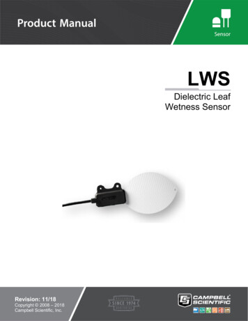
Wireless SOHOInstallation and Operation ManualWireless SOHOInstallation and Operation Manual2.5 Component Description2.4 Hardware Installation2.5.1 LWS-BS Description2.4.1 Wall Mount of the LWS-BS or the LWS-WKTo wall mount the LWS-BS or LWS-WK, perform the following:1. Remove the foot stand.2. Make sure the handset retainer tab is positioned at ‘b’ as shown below figure.Figure 2.4.1-1 Wall Mount of LWS-BS/ LWS-WK3. Make a small mark on the wall where you want the top keyhole slot to align and install a screw (notprovided) so that it protrudes slightly, approx. 2.5mm, from the wall (Figure shown).4. Measure a straight line down 10cm from the mark, and install another screw (not provided).5. Align the keyholes on the back of the phone with the screws in the wall, and then slide the phonedown on the screws to secure the phone.Note:¾Ensure all cables are properly routed and if necessary, that power should be installed beforeaffixing to the wall mount screws.1. Handset3. Speaker5. DND Button7. Volume Up Button9. Antenna11. LCD13. Soft Buttons15. Dial Buttons17. Hold Button19. Speaker Button2. Navigation/OK Key4. Menu Button6. Headset Button8. Volume Down Button10. Ring Indication Light12. Line/Station Selection Buttons14. MSG (Message) Button16. Transfer Button18. Mute Button20. MicrophoneFigure 2.5.1-1 LWS-BS Component Description1516
Wireless SOHOInstallation and Operation ManualWireless SOHOInstallation and Operation Manual2.5.2 LWS-WK Description2.5.3 Wireless Handset DescriptionFigure 2.5.3-1 GDC-400H Component Description1. Handset2. Navigation/OK Key3. Speaker4. Menu Button5. DND Button6. Headset Button7. Volume Up Button8. Volume Down Button9. Ring Indication10. LCD11. Line/Station Selection Buttons 12. Soft Buttons13. MSG Button14. Dial Buttons15. Transfer Button16. Hold Button17. Mute Button18. Speaker Button19. MicrophoneFigure 2.5.2-1 LWS-WK Component DescriptionFigure 2.5.3-2 GDC-450H Component Description1718
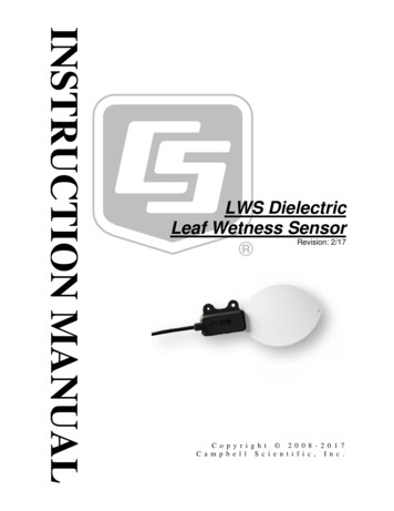
Wireless SOHOInstallation and Operation ManualWireless SOHOInstallation and Operation Manual2.7.2 LCD Display2.6 Hardware Initialization2.7.2.1 LWS-BS2.6.1 LWS-BS and LWS-WK1234567Once the LWS-BS and the LWS-WK have been properly installed in the desired locations, perform thefollowing:81. Plug in the AC/DC adapter to the LWS-BS or the LWS-WK (use only the included AC/DC adapter,SA-B122).2. The LWS-BS or the LWS-WK is powered up and its display on the LCD will be activated.9102.6.2 Wireless HandsetTo start up the Handset:1. Press and hold [] for approximately 2 seconds.2. The handset automatically enters standby mode when a signal is located.3. The handset automatically returns to standby mode whenever it is placed on the charger.To power-down the Handset:1. Press and hold [] for approximately 3 seconds.2.7 Display2.7.1 LCD SpecificationUser can select one of backlight control options (always on, always off, busy state on).2.7.1.1 LWS-BSz 240 x 144 Graphic LCDz Backlit On/Off Control with 3 selectable optionz Ten-Level Contrast Setting11Figure 2.7.2.1-1 the LWS-BS LCD Display Screen1.2.3.Antenna - Displayed when DCTU of LWS-BS works and it can be linked to DECT .Call Forward – Icon indicates the base station is currently set for call forwarding.Mute – Icon indicates if the mute button is activated for blocking voice transmission on your phoneduring a conversion.4. Alarm – Icon indicates the alarm has been set.5. Message – Icon indicates there is at least one new message.6. Missed call – Icon indicates that there are missed calls in your absence.7. USB – Icon indicates a USB memory device is inserted.8. Station Number – Displayed in idle state. If the LWS-BS station has the designated name, thename is displayed.9. Date & Time – Displayed in idle state.10. Calendar – Displayed in idle state.11. Soft Menu – Dependent on the status and menu choices, the current available selections aredisplayed.2.7.2.2 LWS-WK2.7.1.2 LWS-WKz 240 x 42 Graphic LCDz Backlight On/Off Controlz Ten-Level Contrast Setting1. Antenna - Displayed when the LWS-WK is in the range of a LWS-BS where it can be linked.Disappears when it moves out of range. The closer it moves to the base, the stronger RSSI forreception is.2. Message – Icon indicates there is at least one new message.3. Date & Time –Displayed in idle state.4. Keyset Number – Displayed in idle state.5. Soft Menu – Dependent on the status and menu choices, the current available functions aredisplayed.1920
Wireless SOHOInstallation and Operation ManualWireless SOHOInstallation and Operation Manual2.7.2.3 GDC-400H and GDC-450H Wireless Handset2.8 Keypad Description2.8.1 LWS-BS1. Antenna - Displayed when the handset is in the range of a LWS-BS where it can be linked.Disappears when it moves out of range. The closer it moves to the base, the stronger RSSI
LWS-WK Power Adapter Quick User Guide (Wireless Terminal) AC power cord 1.3 Configuration The following image depicts a sample configuration using LWS-BS system and wireless phones, LWS-WK and GDC-400H/450H. Figure 1.3-1 Sample Configuration. Wireless SOHO Installation and Operation Manual .