Transcription
PASSIVE COMPONENTSCHAPTER 10: PASSIVE COMPONENTSINTRODUCTIONSECTION 10.1: CAPACITORSBASICSDIELECTRIC TYPESTOLERANCE, TEMPERATURE, AND OTHER EFFECTSPARASITICSDIELLECTRIC ABSORPTIONCAPACITOR PARASITICS AND DISSIPATION FACTORASSEMBLE CRITICAL COMPONENTS LASTSECTION 10.2: RESISTORS AND POTENTIOMETERSBASICSRESISTOR PARASITICSTHERMOELECTRIC EFFECTSVOLTAGE SENSITIVITY, FAILURE MECHANISMS, AND AGINGRESISTOR EXCESS NOISEPOTENTIOMETERSSECTION 10.3: .2010.2210.2310.2310.2510.27
BASIC LINEAR DESIGN
PASSIVE COMPONENTSINTRODUCTIONCHAPTER 10: PASSIVE COMPONENTSIntroductionWhen designing precision analog circuits, it is critical that users avoid the pitfall of poorpassive component choice. In fact, the wrong passive component can derail even the bestop amp or data converter application. This section includes discussion of some basic trapsof choosing passive components.So, you've spent good money for a precision op amp or data converter, only to find that,when plugged into your board, the device doesn't meet spec. Perhaps the circuit suffersfrom drift, poor frequency response, and oscillations—or simply doesn't achieve expectedaccuracy. Well, before you blame the device, you should closely examine your passivecomponents— including capacitors, resistors, potentiometers, and yes, even the printedcircuit boards. In these areas, subtle effects of tolerance, temperature, parasitics, aging,and user assembly procedures can unwittingly sink your circuit. And all too often theseeffects go unspecified (or underspecified) by passive component manufacturers.In general, if you use data converters having 12 bits or more of resolution, or highprecision op amps, pay very close attention to passive components. Consider the case of a12-bit DAC, where ½ LSB corresponds to 0.012% of full scale, or only 122 ppm. A hostof passive component phenomena can accumulate errors far exceeding this! But, buyingthe most expensive passive components won't necessarily solve your problems either.Often, a correct 25-cent capacitor yields a better-performing, more cost-effective designthan a premium-grade (expensive) part. With a few basics, understanding and analyzingpassive components may prove rewarding, albeit not easy.10.1
BASIC LINEAR DESIGNNotes:10.2
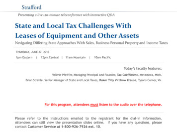
PASSIVE COMPONENTSCAPACITORSSECTION 10.1: CAPACITORSBasicsA capacitor is a passive electronic component that stores energy in the form of anelectrostatic field. In its simplest form, a capacitor consists of two conducting platesseparated by an insulating material called the dielectric. The capacitance is directlyproportional to the surface areas of the plates, and is inversely proportional to theseparation between the plates. Capacitance also depends on the dielectric constant of thesubstance separating the plates.Capacitive reactance is defined as:XC 1/ωC 1/2πfCEq. 10-1where XC is the capacitive reactance, ω is the angular frequency, f is the frequency inHertz, and C is the capacitance.Capacitive reactance is the negative imaginary component of impedance.The complex impedance of an inductor is then given by:Z 1/ jωC 1/j2πfCEq. 10-2where j is the imaginary number.j -1Eq. 10-3Dielectric typesThere are many different types of capacitors, and an understanding of their individualcharacteristics is absolutely mandatory to the design of practical circuits. A thumbnailsketch of capacitor characteristics is shown in the chart of Figure 10.1. Background andtutorial information on capacitors can be found in Reference 2 and many vendor catalogs.With any dielectric, a major potential filter loss element is ESR (equivalent seriesresistance), the net parasitic resistance of the capacitor. ESR provides an ultimate limit tofilter performance, and requires more than casual consideration, because it can vary bothwith frequency and temperature in some types. Another capacitor loss element is ESL(equivalent series inductance). ESL determines the frequency where the net impedance ofthe capacitor switches from a capacitive to inductive characteristic. This varies from aslow as 10 kHz in some electrolytics to as high as 100 MHz or more in chip ceramic types.Both ESR and ESL are minimized when a leadless package is used, and all capacitortypes discussed here are available in surface mount packages, which are preferable forhigh speed uses.10.3
BASIC LINEAR DESIGNThe electrolytic family provides an excellent, cost effective low-frequency filtercomponent, because of the wide range of values, a high capacitance-to-volume ratio, anda broad range of working voltages. It includes general-purpose aluminum electrolytictypes, available in working voltages from below 10 V up to about 500 V, and in size from1 μF to several thousand μF (with proportional case sizes). All electrolytic capacitors arepolarized, and thus cannot withstand more than a volt or so of reverse bias withoutdamage. They have relatively high leakage currents (this can be tens of μA, but isstrongly dependent upon specific family design, electrical size and voltage rating versusapplied voltage). However, this is not likely to be a major factor for basic filteringapplications.Also included in the electrolytic family are tantalum types, which are generally limited tovoltages of 100 V or less, with capacitance of 500 μF or less. In a given size, tantalumsexhibit higher capacitance-to-volume ratios than do the general purpose electrolytics, andhave both a higher frequency range and lower ESR. They are generally more expensivethan standard electrolytics, and must be carefully applied with respect to surge and ripplecurrents.A subset of aluminum electrolytic capacitors is the switching type, which is designed andspecified for handling high pulse currents at frequencies up to several hundred kHz withlow losses. This type of capacitor competes directly with the tantalum type in highfrequency filtering applications, and has the advantage of a much broader range ofavailable values.More recently, high performance aluminum electrolytic capacitors using an organicsemiconductor electrolyte have appeared. These OS-CON families of capacitors featureappreciably lower ESR and higher frequency range than do the other electrolytic types,with an additional feature of low low-temperature ESR degradation.Film capacitors are available in very broad ranges of values and an array of dielectrics,including polyester, polycarbonate, polypropylene, and polystyrene. Because of the lowdielectric constant of these films, their volumetric efficiency is quite low, and a10 μF/50 V polyester capacitor (for example) is actually a handful. Metalized (asopposed to foil) electrodes does help to reduce size, but even the highest dielectricconstant units among film types (polyester, polycarbonate) are still larger than anyelectrolytic, even using the thinnest films with the lowest voltage ratings (50 V). Wherefilm types excel is in their low dielectric losses, a factor which may not necessarily be apractical advantage for filtering switchers. For example, ESR in film capacitors can be aslow as 10 mΩ or less, and the behavior of films generally is very high in terms of Q. Infact, this can cause problems of spurious resonance in filters, requiring dampingcomponents.Typically using a wound layer-type construction, film capacitors can be inductive, whichcan limit their effectiveness for high frequency filtering. Obviously, only noninductivelymade film caps are useful for switching regulator filters. One specific style which isnoninductive is the stacked-film type, where the capacitor plates are cut as smalloverlapping linear sheet sections from a much larger wound drum of dielectric/plate10.4
PASSIVE COMPONENTSCAPACITORSTYPETYPICAL nexpensiveLow DAGood stability ( 120ppm/ C)Damaged by temperatures 85 CLargeHigh inductanceVendors limitedPolypropylene0.001%to0.02%InexpensiveLow DAStable ( 200ppm/ C)Wide range of valuesDamaged by temperatures 105 CLargeHigh inductanceTeflon0.003%to0.02%Low DA availableGood stabilityOperational above 125 CWide range of valuesExpensiveLargeHigh inductancePolycarbonate0.1%Good stabilityLow costWide temperature rangeWide range of valuesLargeDA limits to 8-bit applicationsHigh inductancePolyester0.3%to0.5%Moderate stabilityLow costWide temperature rangeLow inductance (stacked film)LargeDA limits to 8-bit applicationsHigh inductance (conventional)NP0 Ceramic 0.1%Small case sizeInexpensive, many vendorsGood stability (30ppm/ C)1% values availableLow inductance (chip)DA generally low (may not be specified)Low maximum values ( 10nF)MonolithicCeramic(High K) 0.2%Low inductance (chip)Wide range of valuesPoor stabilityPoor DAHigh voltage coefficientMica 0.003%Low loss at HFLow inductanceGood stability1% values availableQuite largeLow maximum values ( 10nF)ExpensiveAluminumElectrolyteVery highLarge valuesHigh currentsHigh voltagesSmall sizeHigh leakageUsually polarizedPoor stability, accuracyInductiveTantalumElectrolyteVery highSmall sizeLarge valuesMedium inductanceHigh leakageUsually polarizedExpensivePoor stability, accuracyFig. 10.1: Capacitor Comparison Chart10.5
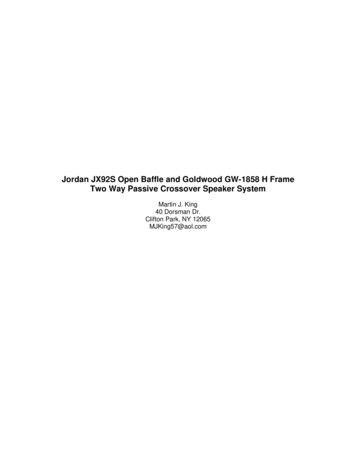
BASIC LINEAR DESIGNmaterial. This technique offers the low inductance attractiveness of a plate sheet stylecapacitor with conventional leads. Obviously, minimal lead length should be used forbest high frequency effectiveness. Very high current polycarbonate film types are alsoavailable, specifically designed for switching power supplies, with a variety of lowinductance terminations to minimize ESL.Dependent upon their electrical and physical size, film capacitors can be useful atfrequencies to well above 10 MHz. At the very high frequencies, stacked film types onlyshould be considered. Some manufacturers are also supplying film types in leadlesssurface-mount packages, which eliminates the lead length inductance.Ceramic is often the capacitor material of choice above a few MHz, due to its compactsize and low loss. But the characteristics of ceramic dielectrics varies widely. Some typesare better than others for various applications, especially power supply decoupling.Ceramic dielectric capacitors are available in values up to several μF in the high-Kdielectric formulations of X7R and Z5U, at voltage ratings up to 200 V. NP0 (also calledCOG) types use a lower dielectric constant formulation, and have nominally zero TC,plus a low voltage coefficient (unlike the less stable high-K types). The NP0 types arelimited in available values to 0.1 μF or less, with 0.01 μF representing a more practicalupper limit.Multilayer ceramic “chip caps” are increasingly popular for bypassing and filtering at10 MHz or more, because their very low inductance design allows near optimum RFbypassing. In smaller values, ceramic chip caps have an operating frequency range to1 GHz. For these and other capacitors for high frequency applications, a useful value canbe ensured by selecting a value which has a self-resonant frequency above the highestfrequency of interest.All capacitors have some finite ESR. In some cases, the ESR may actually be helpful inreducing resonance peaks in filters, by supplying “free” damping. For example, ingeneral purpose, tantalum and switching type electrolytics, a broad series resonanceregion is noted in an impedance versus frequency plot. This occurs where Z falls to aminimum level, which is nominally equal to the capacitor’s ESR at that frequency. In anexample below, this low Q resonance is noted to encompass quite a wide frequencyrange, several octaves in fact. Contrasted to the very high Q sharp resonances of film andceramic caps, this low Q behavior can be useful in controlling resonant peaks.In most electrolytic capacitors, ESR degrades noticeably at low temperature, by as muchas a factor of 4 to 6 times at –55 C versus the room temperature value. For circuits wherea high level of ESR is critical, this can lead to problems. Some specific electrolytic typesdo address this problem, for example within the HFQ switching types, the –10 C ESR at100 kHz is no more than 2 that at room temperature. The OSCON electrolytics have anESR versus temperature characteristic which is relatively flat.Figure 10.2 illustrates the high frequency impedance characteristics of a number ofelectrolytic capacitor types, using nominal 100 μF/20 V samples. In these plots, theimpedance, Z , vs. frequency over the 20 Hz to 200 kHz range is displayed using a highresolution 4-terminal setup. Shown in this display are performance samples for a10.6
PASSIVE COMPONENTSCAPACITORS100 μF/25 V general purpose aluminum unit, a 120 μF/25 V HFQ unit, a 100 μF/20 Vtantalum bead type, and a 100 μF/20 V OS-CON unit (lowest curve @ right). While theHFQ and tantalum samples are close in 100 kHz impedance, the general purpose unit isabout four times worse. The OS-CON unit is nearly an order of magnitude lower in100 kHz impedance than the tantalum and switching electrolytic types.10010 Z (Ω )1GEN. PURPOSE AL100μF, 25V"HFQ" 120μF, 25VTANTALUM BEAD100μF, 20V0.1OS-CON AL100μF, 20V10m1m201001k10k100k200kFREQUENCY (Hz)Figure 10.2: Impedance Z(Ω) vs. Frequency for 100 μFElectrolytic Capacitors (AC Current 50 mA RMS)As noted above, all real capacitors have parasitic elements which limit their performance.As an insight into why the impedance curves of Figure 10.2 appear the way they do, a(simplified) model for a 100 μF/20 V tantalum capacitor is shown in Figure 10.3.The electrical network representing this capacitor is shown, and it models the ESR andESL components with simple R and L elements, plus a 1 MΩ shunt resistance. While thissimple model ignores temperature and dielectric absorption effects which occur in thereal capacitor, it is still sufficient for this discussion.C100 µFRS0.12 ΩRP1 MΩLS15 nHFigure 10.3: Simplified Spice Model for a Leaded100 μF/20 V Tantalum Electrolytic Capacitor10.7
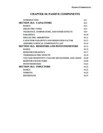
BASIC LINEAR DESIGNWhen driven with a constant level of ac current swept from 10 Hz to 100 MHz, thevoltage across this capacitor model is proportional to its net impedance, which is shownin Figure 10.4.100(100,000, 15.916) Z (Ω )10(10.000M, 949.929m)1.0(125.893K, 120.003m)100m101001.0k10k100k1.0M10M100MFREQUENCY (Hz)Figure 10.4: 100 μF/20 V Tantalum Capacitor Simplified ModelImpedance (Ω) vs. Frequency (Hz)At low frequencies the net impedance is almost purely capacitive, as noted by the 100 Hzimpedance of 15.9 Ω. At the bottom of this “bathtub” curve, the net impedance isdetermined by ESR, which is shown to be 0.12 Ω at 125 kHz. Above about 1 MHz thiscapacitor becomes inductive, and impedance is dominated by the effect of ESL. Whilethis particular combination of capacitor characteristics have been chosen purposely tocorrespond to the tantalum sample used with Figure 10.4, it is also true that allelectrolytics will display impedance curves which are similar in general shape. Theminimum impedance will vary with the ESR, and the inductive region will vary with ESL(which in turn is strongly effected by package style). The simulation curve of Figure 10.4can be considered as an extension of the 100 μF/20 V tantalum capacitor curve fromFigure 10.2.10.8
PASSIVE COMPONENTSCAPACITORSTolerance, Temperature, and Other EffectsIn general, precision capacitors are expensive and—even then— not necessarily easy tobuy. In fact, choice of capacitance is limited both by the range of available values, andalso by tolerances. In terms of size, the better performing capacitors in the film familiestend to be limited in practical terms to 10 μF or less (for dual reasons of size andexpense). In terms of low value tolerance, 1% is possible for NP0 ceramic and somefilm devices, but with possibly unacceptable delivery times. Many film capacitors can bemade available with tolerances of less than 1%, but on a special order basis only.Most capacitors are sensitive to temperature variations. DF, DA, and capacitance valueare all functions of temperature. For some capacitors, these parameters varyapproximately linearly with temperature, in others they vary quite nonlinearly. Althoughit is usually not important for SH applications, an excessively large temperaturecoefficient (TC, measured in ppm/ C) can prove harmful to the performance of precisionintegrators, voltage-to-frequency converters, and oscillators. NP0 ceramic capacitors,with TCs as low as 30 ppm/ C, are the best for stability, with polystyrene andpolypropylene next best, with TCs in the 100 ppm/ C to 200 ppm/ C range. On the otherhand, when capacitance stability is important, one should stay away from types with TCsof more than a few hundred ppm/ C, or in fact any TC which is nonlinear.A capacitor's maximum working temperature should also be considered, in light of theexpected environment. Polystyrene capacitors, for instance, melt near 85 C, compared toTeflon's ability to survive temperatures up to 200 C.Sensitivity of capacitance and DA to applied voltage, expressed as voltage coefficient,can also hurt capacitor performance within a circuit application. Although capacitormanufacturers don’t always clearly specify voltage coefficients, the user should alwaysconsider the possible effects of such factors. For instance, when maximum voltages areapplied, some high-K ceramic devices can experience a decrease in capacitance of 50%or more. This is an inherent distortion producer, making such types unsuitable for signalpath filtering, for example, and better suited for supply bypassing. Interestingly, NP0ceramics, the stable dielectric subset from the wide range of available ceramics, do offergood performance with respect to voltage coefficient.Similarly, the capacitance, and dissipation factor of many types vary significantly withfrequency, mainly as a result of a variation in dielectric constant. In this regard, the betterdielectrics are polystyrene, polypropylene, and Teflon.10.9
BASIC LINEAR DESIGNParasiticsMost designers are generally familiar with the range of capacitors available. But themechanisms by which both static and dynamic errors can occur in precision circuitdesigns using capacitors are sometimes easy to forget, because of the tremendous varietyof types available. These include dielectrics of glass, aluminum foil, solid tantalum andtantalum foil, silver mica, ceramic, Teflon, and the film capacitors, including polyester,polycarbonate, polystyrene, and polypropylene types. In addition to the traditional leadedpackages, many of these are now also offered in surface mount styles.Figure 10.5 is a workable model of a nonideal capacitor. The nominal capacitance, C, isshunted by a resistance RP, which represents insulation resistance or leakage. A secondresistance, RS—equivalent series resistance, or ESR,—appears in series with thecapacitor and represents the resistance of the capacitor leads and plates.RPRSL(ESR)(ESL)CRDACDAFigure 10.5: A Nonideal Capacitor Equivalent CircuitIncludes Parasitic ElementsNote that capacitor phenomena aren't that easy to separate out. The matching ofphenomena and models is for convenience in explanation. Inductance, L—the equivalentseries inductance, or ESL,—models the inductance of the leads and plates. Finally,resistance RDA and capacitance CDA together form a simplified model of a phenomenonknown as dielectric absorption, or DA. It can ruin fast and slow circuit dynamicperformance. In a real capacitor RDA and CDA extend to include multiple parallel sets.These parasitic RC elements can act to degrade timing circuits substantially, and thephenomenon is discussed further below.10.10
PASSIVE COMPONENTSCAPACITORSDielectric AbsorptionDielectric absorption, which is also known as "soakage" and sometimes as "dielectrichysteresis"—is perhaps the least understood and potentially most damaging of variouscapacitor parasitic effects. Upon discharge, most capacitors are reluctant to give up all oftheir former charge, due to this memory consequence.Figure 10.6 illustrates this effect. On the left of the diagram, after being charged to thesource potential of V volts at time to, the capacitor is shorted by the switch S1 at time t1,discharging it. At time t2, the capacitor is then open-circuited; a residual voltage slowlybuilds up across its terminals and reaches a nearly constant value. This error voltage isdue to DA, and is shown in the right figure, a time/voltage representation of thecharge/discharge/recovery sequence. Note that the recovered voltage error is proportionalto both the original charging voltage V, as well as the rated DA for the capacitor in use.VOS1t0VVt1CV x DAVOt2tt0t1t2Figure 10.6: A Residual Open-Circuit Voltage After Charge/DischargeCharacterizes Capacitor Dielectric AbsorptionStandard techniques for specifying or measuring dielectric absorption are few and farbetween. Measured results are usually expressed as the percentage of the originalcharging voltage that reappears across the capacitor. Typically, the capacitor is chargedfor a long period, then shorted for a shorter established time. The capacitor is thenallowed to recover for a specified period, and the residual voltage is then measured (seeReference 8 for details). While this explanation describes the basic phenomenon, it isimportant to note that real-world capacitors vary quite widely in their susceptibility tothis error, with their rated DA ranging from well below to above 1%, the exact numberbeing a function of the dielectric material used.In practice, DA makes itself known in a variety of ways. Perhaps an integrator refuses toreset to zero, a voltage-to-frequency converter exhibits unexpected nonlinearity, or asample-hold (SH) exhibits varying errors. This last manifestation can be particularlydamaging in a data-acquisition system, where adjacent channels may be at voltageswhich differ by nearly full scale, as shown below.Figure 10.7 illustrates the case of DA error in a simple SH. On the left, switches S1 andS2 represent an input multiplexer and SH switch, respectively. The multiplexer output10.11
BASIC LINEAR DESIGNvoltage is VX, and the sampled voltage held on C is VY, which is buffered by the op ampfor presentation to an ADC. As can be noted by the timing diagram on the right, a DAerror voltage, , appears in the hold mode, when the capacitor is effectively open circuit.This voltage is proportional to the difference of voltages V1 and V2, which, if at oppositeextremes of the dynamic range, exacerbates the error. As a practical matter, the bestsolution for good performance in terms of DA in a SH is to use only the best capacitor.The DA phenomenon is a characteristic of the dielectric material itself, although inferiormanufacturing processes or electrode materials can also affect it. DA is specified as apercentage of the charging voltage. It can range from a low of 0.02% for Teflon,polystyrene, and polypropylene capacitors, up to a high of 10% or more for someelectrolytics. For some time frames, the DA of polystyrene can be as low as 0.002%.V1TO ADCVYS1S2V1VXVYV2 (V1-V2) DAV2V3VXVNCOPENS2CLOSEDFigure 10.7: Dielectric Absorption Induces Errors in SH ApplicationsCommon high-K ceramics and polycarbonate capacitor types display typical DA on theorder of 0.2%, it should be noted this corresponds to ½ LSB at only 8 bits! Silver mica,glass, and tantalum capacitors typically exhibit even larger DA, ranging from 1.0% to5.0%, with those of polyester devices failing in the vicinity of 0.5%. As a rule, if thecapacitor spec sheet doesn’t specifically discuss DA within your time frame and voltagerange, exercise caution! Another type with lower specified DA is likely a better choice.DA can produce long tails in the transient response of fast-settling circuits, such as thosefound in high pass active filters or ac amplifiers. In some devices used for suchapplications, Figure 10.5's RDA-CDA model of DA can have a time constant ofmilliseconds. Much longer time constants are also quite usual. In fact, several paralleledRDA-CDA circuit sections with a wide range of time constants can model some devices.In fast-charge, fast-discharge applications, the behavior of the DA mechanism resembles"analog memory"; the capacitor in effect tries to remember its previous voltage.In some designs, you can compensate for the effects of DA if it is simple and easilycharacterized, and you are willing to do custom tweaking. In an integrator, for instance,the output signal can be fed back through a suitable compensation network, tailored tocancel the circuit equivalent of the DA by placing a negative impedance effectively in10.12
PASSIVE COMPONENTSCAPACITORSparallel. Such compensation has been shown to improve SH circuit performance byfactors of 10 or more (Reference 6).Capacitor Parasitics and Dissipation FactorIn Figure 10.5, a capacitor's leakage resistance, RP, the effective series resistance, RS, andeffective series inductance, L, act as parasitic elements, which can degrade an externalcircuit’s performance. The effects of these elements are often lumped together anddefined as a dissipation factor, or DF.A capacitor's leakage is the small current that flows through the dielectric when a voltageis applied. Although modeled as a simple insulation resistance (RP) in parallel with thecapacitor, the leakage actually is nonlinear with voltage. Manufacturers often specifyleakage as a megaohm-microfarad product, which describes the dielectric’s self-dischargetime constant, in seconds. It ranges from a low of 1s or less for high-leakage capacitors,such as electrolytic devices, to the 100's of seconds for ceramic capacitors. Glass devicesexhibit self-discharge time-constants of 1000 or more; but the best leakage performanceis shown by Teflon and the film devices (polystyrene, polypropylene), with timeconstants exceeding 1,000,000 megaohm-microfarads. For such a device, externalleakage paths—created by surface contamination of the device's case or in the associatedwiring or physical assembly—can overshadow the internal dielectric-related leakage.Equivalent series inductance, ESL (Figure 10.5) arises from the inductance of thecapacitor leads and plates, which, particularly at the higher frequencies, can turn acapacitor's normally capacitive reactance into an inductive reactance. Its magnitudestrongly depends on construction details within the capacitor. Tubular wrapped-foildevices display significantly more lead inductance than molded radial-leadconfigurations. Multilayer ceramic and film-type devices typically exhibit the lowestseries inductance, while ordinary tantalum and aluminum electrolytics typically exhibitthe highest. Consequently, standard electrolytic types, if used alone, usually proveinsufficient for high speed local bypassing applications. Note however that there also aremore specialized aluminum and tantalum electrolytics available, which may be suitablefor higher speed uses. These are the types generally designed for use in switch-modepower supplies, which are covered more completely in a following section.Manufacturers of capacitors often specify effective series impedance by means ofimpedance-versus-frequency plots. Not surprisingly, these curves show graphically apredominantly capacitive reactance at low frequencies, with rising impedance at higherfrequencies because of the effect of series inductance.Effective series resistance, ESR (resistor RS of Figure 10.5), is made up of the resistanceof the leads and plates. As noted, many manufacturers lump the effects of ESR, ESL, andleakage into a single parameter called dissipation factor, or DF. Dissipation factormeasures the basic inefficiency of the capacitor. Manufacturers define it as the ratio ofthe energy lost to energy stored per cycle by the capacitor. The ratio of ESR to totalcapacitive reactance—at a specified frequency—approximates the dissipation factor,which turns out to be equivalent to the reciprocal of the figure of merit, Q. Stated as an10.13
BASIC LINEAR DESIGNapproximation, Q 1/DF (with DF in numeric terms). For example, a DF of 0.1% isequivalent to a fraction of 0.001; thus the inverse in terms of Q would be 1000.Dissipation factor often varies as a function of both temperature and frequency.Capacitors with mica and glass dielectrics generally have DF values from 0.03% to 1.0%.For ordinary ceramic devices, DF ranges from a low of 0.1 % to as high as 2.5 % at roomtemperature. And electrolytics usually exceed even this level. The film capacitors are thebest as a group, with DFs of less than 0.1 %. Stable-dielectric ceramics, notably the NP0(also called COG) types, have DF specs comparable to films (more below).Assemble Critical Components LastThe designer's worries don't end with the design process. Some common printed circuitassembly techniques can prove ruinous to even the best designs. For instance, somecommonly used cleaning solvents can infiltrate certain electrolytic capacitors—thosewith rubber end caps are particularly susceptible. Even worse, some of the filmcapacitors, polystyrene in particular, actually melt when contacted by some solvents.Rough handling of the leads can damage still other capacitors, creating random or evenintermittent circuit problems. Etched-foil types are particularly delicate in this regard. Toavoid these difficulties it may be advisable to mount especially critical components as thelast step in the board assembly process—if possible.Designers should also consider the natural failure mechanisms of capacitors. Metallizedfilm devices, for instance, often self-heal. They initially fail due to conductive bridgesthat develop through small perforations in the dielectric film. But, the resulting faultcurrents can generate sufficient heat to destroy the bridge, thus returning the capacitor tonormal operation (at a slightly lower capacitance). Of course, applications inhigh-impedance circuits may not develop sufficient current to clear the bridge, so thedesigner must be wary
passive components may prove rewarding, albeit not easy. BASIC LINEAR DESIGN 10.2 Notes: PASSIVE COMPONENTS CAPACITORS 10.3 SECTION 10.1: CAPACITORS Basics A capacitor is a passive electronic component that stores energy in the form of an electrostatic field. In its simplest form, a capaci