Transcription
ELECTRIC COOKTOPINSTALLATION INSTRUCTIONSINSTRUCTIONS D’INSTALLATION DE LA TABLEDE CUISSON ÉLECTRIQUEINSTRUCCIONES DE INSTALACIÓN DELA PARRILLA ELÉCTRICATable of Contents/Table des matières/Tabla de contenidosCOOKTOP SAFETY.2INSTALLATION REQUIREMENTS.2Tools and Parts.2Location Requirements.2Electrical Requirements.4INSTALLATION INSTRUCTIONS.5Prepare Cooktop for Installation.5Install Cooktop.5Make Electrical Connection.7Attach Cooktop to Countertop.9Complete Installation.9SÉCURITÉ DE LA TABLE DE CUISSON.10EXIGENCES D’INSTALLATION.10Outils et pièces.10Exigences d’emplacement.10Spécifications électriques.12INSTRUCTIONS D’INSTALLATION.13Préparation de la table de cuisson pour l’installation.13Installation de la table de cuisson.13Raccordement électrique.15Fixation de la table de cuisson au plan de travail.17Achever l’installation.17SEGURIDAD DE LA PARRILLA ELÉCTRICA.18REQUISITOS DE INSTALACIÓN.18Herramientas y piezas.18Requisitos de ubicación.18Requisitos eléctricos.20INSTRUCCIONES DE INSTALACIÓN.21Preparación de la parrilla eléctrica para la instalación.21Instalación de la parrilla eléctrica.21Haga la conexión del suministro eléctrico.23Cómo fijar la parrilla eléctrica al mostrador.25Completar la instalación.25IMPORTANT:Save for local electrical inspector's use.IMPORTANT :À conserver pour consultation par l'inspecteur local des installations électriques.IMPORTANT :Ahorre para el uso del inspector eléctrico local.W11206696D05-Sep-2019 13:08:04 EDT RELEASEDIn some European factories the letter "W" of the part code mentioned herein will be automaticallyreplaced by the number "4000" (e.g. "W12345678" becomes "400012345678")
COOKTOP SAFETYYour safety and the safety of others are very important.We have provided many important safety messages in this manual and on your appliance. Always read and obey all safetymessages.This is the safety alert symbol.This symbol alerts you to potential hazards that can kill or hurt you and others.All safety messages will follow the safety alert symbol and either the word “DANGER” or “WARNING.”These words mean:You can be killed or seriously injured if you don't immediatelyfollow instructions.DANGERYou can be killed or seriously injured if you don't followinstructions.WARNINGAll safety messages will tell you what the potential hazard is, tell you how to reduce the chance of injury, and tell you what canhappen if the instructions are not followed.INSTALLATION REQUIREMENTSTools and PartsLocation RequirementsGather the required tools and parts before starting installation.Read and follow the instructions provided with any tools listedhere.IMPORTANT: Observe all governing codes and ordinances.When installing cooktop, use minimum dimensions given. To eliminate the risk of burns or fire by reaching over theheated surface units, cabinet storage space located abovethe surface units should be avoided. If cabinet storage is tobe provided, the risk can be reduced by installing a rangehood that projects horizontally a minimum of 5" (12.7 cm)beyond the bottom of the cabinets. The cooktop must be a specified cooktop that is approvedto be installed either alone or over an undercounter built-inoven. Check the cooktop base for an approved installationlabel. If you do not find this label, contact your dealer toconfirm that your cooktop is approved. The cooktop must be installed in a level countertop. Ovens approved for this type of installation will have anapproval label located on the top of the oven. If you donot find this label, contact your dealer to confirm that youroven is approved. Refer to oven manufacturer’s InstallationInstructions for approval for built-in undercounter use andproper cutout dimensions. The cooktop should be installed away from strong draftareas, such as windows, doors, fans or strong heating vents.The cooktop should be located for convenient use in thekitchen.Tools needed Tape measure Marker or pencil 1/4" (6.35 mm) nut driver Pliers Flat-blade screwdriverParts supplied Foam strip roll 2½" (6.4 cm) clamping Clamping brackets (2) Screws (2)Parts needed A UL listed or CSA approved connector for 1/2" (1.3 cm)diameter conduitUL listed wire connectorsCheck local codes. Check existing electrical supply. See the“Electrical Requirements” section.It is recommended that all electrical connections be made by alicensed, qualified electrical installer. 205-Sep-2019 13:08:04 EDT RELEASEDIn some European factories the letter "W" of the part code mentioned herein will be automaticallyreplaced by the number "4000" (e.g. "W12345678" becomes "400012345678")
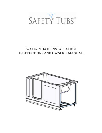
Use the countertop opening dimensions that are givenwith these Installation Instructions. Given dimensions areminimum clearances and provide 0" (0 cm) clearance.Grounded electrical supply is required. See “ElectricalRequirements” section.IMPORTANT: To avoid damage to your cabinets, check withyour builder or cabinet supplier to make sure that the materialsused will not discolor, delaminate, or sustain other damage. Cabinet DimensionsIMPORTANT: If installing a range hood or microwave hoodcombination above cooking surface, follow the range hood ormicrowave hood combination installation instructions fordimensional clearances above the cooktop surface.ADProduct DimensionsBBCACELGFHDIKJEFA. Glass depth - black and white models - 213/4" (55.2 cm)Glass depth - Whirlpool and Maytag stainless steel models 227/8" (58.0 cm)Glass depth - KitchenAid stainless steel models - 215/8" (54.9 cm)B. Glass width - 24" (60.9 cm) models - 23¹³/16" (60.5 cm)Glass width - 30" black and white (76.2 cm) models 30¹³/16" (78.4 cm)Glass width - Whirlpool and Maytag 30" stainless steel (76.2 cm)models - 30¹3/16" (78.4 cm)Glass width - KitchenAid 30" stainless steel (76.2 cm) models 303/8" (77.1 cm)Glass width - 36" black and white (91.4 cm) models 365/16" (92.3 cm)Glass width - Whirlpool 36" stainless steel (91.4 cm) models 365/16" (92.3 cm)Glass width - Maytag 36" stainless steel (91.4 cm) models 361/16" (91.5 cm)Glass width - KitchenAid 36" stainless steel (91.4 cm) models 357/8" (91.0 cm)C. Frame depth - 205 16" (51.6 cm)D. Frame width - 24" (60.9 cm) models - 2159/64" (55.7 cm)Frame width - 30" (76.2 cm) models - 29" (73.7 cm)Frame width - 36" (91.4 cm) models - 347/16" (87.5 cm)E. Cooktop height with bottom heat shield - 37 8" (9.8 cm)Cooktop height lighted knobs - 415/16" (12.55 cm)F. Cooktop height including conduit (located at rear of cooktop, rightside) - 5" (12.7 cm)Cooktop height lighted knobs, including conduit (located at rear ofcooktop, right side) - 61/16" (15.4 cm)A. 24" (60.9 cm) on 24" models; 30" (76.2 cm) on 30" models;36" (91.4 cm) on 36" modelsB. Combustible area above countertop (shown by dashed box above)C. 30" (76.2 cm) minimum clearance between top of cooktopplatform and bottom of uncovered wood or metal cabinet(24" [61 cm] minimum clearance if bottom of wood or metalcabinet is covered by not less than 1/4" [0.6 cm] flame retardantmillboard covered with not less than No. 28 MSG sheet steel,0.015" [0.04 cm] stainless steel, or 0.024" [0.06 cm] aluminumor 0.020" [0.05 cm] copper)D. 13" (33 cm) recommended upper cabinet depthE. 2" (5.1 cm)F. 20¹ 2" (52.0 cm) recommended cutout.Will fit in cutout from 20³ 8"-209 16" (51.8-52.2 cm).G. 18" (45.7 cm) minimum clearance from upper cabinet tocountertop within minimum horizontal clearances to cooktopH. Junction box or outlet: 7" (17.8 cm) minimum from top ofcountertopI. Junction box or outlet: 9" (23.0 cm) maximum from right sideof cabinetJ. 29¹ 2" (74.9 cm) recommended cutout on 30" (76.2 cm) models.Will fit in cutout from 29¹ 16"-299 16" (73.8-75.1 cm) on 30" (76.2 cm)models.35¹ 2" (90.2 cm) recommended cutout on 36" (91.4 cm) models.Will fit in cutout from 349 16"-359 16" (87.8-90.3 cm) on 36" (91.4 cm)models.225/16" (56.67 cm) recommended cutout on 24" (61.0 cm)Will fit in cutout from 221/4"- 223/7" (56.4 - 57.0 cm) on24" (61.0 cm) models.K. 21/2" (6.35 cm) minimum distance to nearest left and right sidecombustible surface above cooktopL. 11/2" (3.81 cm) minimum clearance between back wall andcountertopNOTES: After making the countertop cutout, some installationsmay require notching down the base cabinet side walls to clearthe cooktop base. To avoid this modification, use a base cabinetwith sidewalls wider than the cutout.If cabinet has a drawer, a 5¹ 2" (14.0 cm) depth clearance fromthe top of the countertop to the top of the drawer (or otherobstruction) in base cabinet is required.AA. Location of Power Cord (length of power cord is48" (121.9 cm), including the conduit)05-Sep-2019 13:08:04 EDT RELEASED3In some European factories the letter "W" of the part code mentioned herein will be automaticallyreplaced by the number "4000" (e.g. "W12345678" becomes "400012345678")
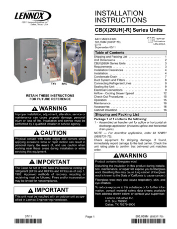
Electrical RequirementsThe cooktop is rated for 120/208 V or 120/240 V. Somemodels have a neutral (white) wire.For power requirements, refer to the following table: WARNINGElectrical Shock HazardDisconnect power before servicing.Family ModelNumberElectrical Ratings at 60 Hz208 V 240 V WCE55US0H5.0 kW6.7 kWWCE55US4H5.0 kW6.7 kWWCE55US6H6.0 kW8.0 kWWCE77US0H6.4 kW8.5 kWUse 8 gauge copper wire.WCE77US6H6.4 kW8.5 kWElectrically ground cooktop.WCE97US0H6.8 kW9.1 kWFailure to follow these instructions can result in death,fire, or electrical shock.WCE97US6H6.8 kW9.1 kWMEC8830H6.5 kW8.6 kWMEC8836H7.4 kW9.9 kWKCES550H7.9 kW10.5 kWKCES556H7.9 kW10.5 kWKCES950H7.2 kW9.6 kWKCES956H7.2 kW9.6 kWJEC3430H6.4 kW8.5 kWJEC3536H7.9 kW10.5 kWJEC4424H5.5 kW7.3 kWJEC4430H7.2 kW9.6 kWJEC4536H7.2 kW9.6 kWIf codes permit and a separate ground wire is used, it isrecommended that a qualified electrical installer determine thatthe ground path and wire gauge are in accordance with localcodes.Check with a qualified electrical installer if you are not sure thecooktop is properly grounded.Make sure that the electrical connection and wire size areadequate and in conformance with the National Electrical Code,ANSI/NFPA 70-latest edition or CSA Standards C22.1-94,Canadian Electrical Code, Part 1 and C22.2 No. O-M91-latestedition, and all local codes and ordinances.A copy of the above code standards can be obtained from:National Fire Protection Association1 Batterymarch ParkQuincy, MA 02169-7471CSA International8501 East Pleasant Valley RoadCleveland, OH 44131-5575Before You Make the Electrical Connection:To properly install your cooktop, you must determine the type ofelectrical connection you will be using and follow the instructionsprovided for it here.Use a 3-wire or 4-wire, single phase, 120/208 V or 120/240 V,60 Hz, AC only. The model/serial number rating plate is locatedon the metal cabinet underneath the cooktop.See the following illustration. The cooktop should be connected directly to the junctionbox through flexible, armored or nonmetallic sheathed,copper cable. The flexible, armored cable extending from thefuse box or circuit breaker box should be connected directlyto the junction box. Locate the junction box to allow as much slack as possiblebetween the junction box and the cooktop so that thecooktop can be moved if servicing becomes necessary inthe future.Do not cut the conduit. Use the length of conduit provided.A UL listed or CSA approved conduit connector must beprovided at each end of the power supply cable (at the cooktopand at the junction box). A listed conduit connector is alreadyprovided at the cooktop. If the house has aluminum wiring follow the procedurebelow:Connect the aluminum wiring using special connectorsand/or tools designed and UL listed for joining copper toaluminum.Follow the electrical connector manufacturer’s recommendedprocedure. Aluminum/copper connection must conform withlocal codes and industry accepted wiring practices. AA. Model/serial number plateAccording to the NEC, NFPA 70 - 2017 Table 220.55 the demandload for products rated 8.75 kW or less is 80% of the ratedvalue.Products rated 8.75 to 12 kW have a demand load of 8 kW.405-Sep-2019 13:08:04 EDT RELEASEDIn some European factories the letter "W" of the part code mentioned herein will be automaticallyreplaced by the number "4000" (e.g. "W12345678" becomes "400012345678")
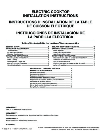
INSTALLATION INSTRUCTIONSPrepare Cooktop for InstallationWARNINGExcessive Weight HazardUse two or more people to move and install cooktop.Failure to do so can result in back or other injury.Decide on the final location for the cooktop. Avoid drilling into orsevering existing wiring during installation.1. Using 2 or more people, place the cooktop upside downon a covered surface using the foam end posts from thepackaging. Make sure that the knobs are not resting on thefoam.2. Remove foam strip roll from the package containingliterature. The roll contains four 1/4" (6.4 mm) strips of foam.Remove one strip at a time. Apply the foam strip adhesivearound bottom of the four edges of the cooktop glass,following the edges of the glass.NOTE: The foam strip helps avoid damage to the underside ofthe cooktop glass from debris and helps the cooktop sit flat onuneven counters.ABInstall CooktopStyle 1: Cooktop over undercounter built-in ovenIMPORTANT: Clamping brackets should not be used.1. Using 2 or more people, place cooktop right side up intothe cutout.NOTE: Make sure that the front edge of the cooktop isparallel to the front edge of the countertop. If repositioningis needed, lift entire cooktop up from cutout to avoidscratching the countertop.Style 2: Cooktop over cabinets1. Determine whether your cabinet construction providesclearance for installing clamping brackets at cooktopbase ends.24" (60.9 cm), 30" (76.2 cm) and 36" (91.4 cm) traditionalmodelsABCA. Cooktop base bottomB. Attachment screwC. Clamping bracket2. The clamping brackets can be installed before or after thecooktop is placed into the cutout. Complete the followingsteps for the option you choose.CA. Cooktop baseB. 1/4" (6.4 mm) Foam stripC. CooktopNOTE: For some models with trim on the front glass edge, applythe foam strip side down around bottom of the cooktop glassonly on LEFT, RIGHT and BACK SIDE.LEFT SIDERIGHT SIDEBACK SIDE05-Sep-2019 13:08:04 EDT RELEASED5In some European factories the letter "W" of the part code mentioned herein will be automaticallyreplaced by the number "4000" (e.g. "W12345678" becomes "400012345678")
Installing Brackets Before Placing Cooktop in Cutout1. Using 2 or more people, place the cooktop upside downon a covered surface using the foam end posts from thepackaging. Make sure that the knobs are not resting on thefoam.2. Remove the attachment screws for the bracket locationsfrom the bottom of the cooktop base.3. Select bracket mounting holes that will allow the bracket toextend far enough out from the cooktop for the installation of2¹ 2" (6.4 cm) clamping screws. See the “Attach Cooktop toCountertop” section for illustration of clamping screwinstallation.Installing Brackets After Placing Cooktop in Cutout1. Using 2 or more people, place cooktop right side up into thecutout.NOTE: Make sure that the front edge of the cooktop isparallel to the front edge of the countertop. If repositioningis needed, lift entire cooktop up from cutout to avoidscratching the countertop.2. Remove the attachment screws for the selected bracketlocations from the bottom of the cooktop base.3. Select bracket mounting holes that will allow the bracket toextend far enough out from the cooktop for the installationof 2¹ 2" (6.4 cm) clamping screws.FABEECBCDDCA.B.C.D.CooktopCooktop baseAttachment screwClamping bracket (extends far enough beyond cooktopbase to allow installation of clamping screws)E. 2¹ 2" (6.4 cm) clamping screw (to be installed in “AttachCooktop to Countertop”)F. CountertopAA.B.C.D.E.Edge of cooktop base bottomClamping bracketBracket mounting holesBracket clamping holeAttachment screw4. Attach brackets to cooktop base bottom with bracketattachment screws using the bracket mounting holesselected in Step 3.5. Rotate brackets so they do not extend beyond edge ofcooktop base.6. Tighten attachment screws enough to hold brackets in placewhen cooktop is placed in cutout.7. Using 2 or more people, turn the cooktop right side up andplace in cutout.NOTE: Make sure that the front edge of the cooktop isparallel to the front edge of the countertop. If repositioningis needed, lift entire cooktop up from cutout to avoidscratching the countertop.8. Loosen the screws and rotate the brackets so that they areperpendicular to the edge of the cooktop base and extendbeyond its edge. Securely tighten screws.605-Sep-2019 13:08:04 EDT RELEASED4. Attach brackets to cooktop base bottom with bracketattachment screws using the bracket mounting holesselected in Step 3. Securely tighten screws.In some European factories the letter "W" of the part code mentioned herein will be automaticallyreplaced by the number "4000" (e.g. "W12345678" becomes "400012345678")
Make Electrical ConnectionWARNING4-Wire Cable from Power Supply to 4-Wire Cablefrom CooktopIMPORTANT: Use the 4-wire cable from power supply wherelocal codes do not permit connecting the frame-groundconductor to the neutral (white) junction box wire.ABElectrical Shock HazardEDisconnect power before servicing.FGUse 8 gauge copper wire.Electrically ground cooktop.Failure to follow these instructions can result in death,fire, or electrical shock.This cooktop is manufactured with a frame connected, green orbare ground wire. Connect the cooktop cable to the junction boxthrough the UL listed or CSA approved conduit connector.Electrical Connection OptionsFor cooktops with a 4-wire cableIf your home has:And you will beconnecting to:Go to Section:4-wire directA fused disconnector circuit breakerbox4-Wire Cable fromPower Supply to4-Wire Cable fromCooktopA fused disconnector circuit breakerbox3-Wire Cable fromPower Supply to4-Wire Cable fromCooktop5"(12,7 cm)3-wire direct3¹ ₂"(8.9 cm)For cooktops with a 3-wire cable:If your home has:And you will beconnecting to:Go to Section:4-wire directA fused disconnector circuit breakerbox4-Wire Cable fromPower Supply to3-Wire Cable fromCooktopA fused disconnector circuit breakerbox3-Wire Cable fromPower Supply to3-Wire Cable fromCooktop5"(12,7 cm)3-wire direct3¹ ₂"(8.9 cm)05-Sep-2019 13:08:04 EDT RELEASEDHCIDA.B.C.D.E.4-wire cable from power supplyBlack wiresBare or green wires4-wire cable from cooktopJunction boxF.G.H.I.White wiresUL listed wire connectorRed wiresUL listed or CSA approvedconduit connector1. Disconnect power.2. Remove junction box cover, if present.3. Connect the flexible cable conduit from the cooktop to thejunction box using a UL listed or CSA approved connectorfor 1/2" (1.3 cm) conduit.4. Tighten screws on conduit connector if present.5. Connect the two black wires together using the UL listedwire connectors.6. Connect the two red wires together using the UL listed wireconnectors.7. Connect the two white wires together using the UL listedwire connectors.8. Connect the green or bare ground wire from the cooktopcable to the green or bare ground wire (in the junction box)using the UL listed wire connectors.9. Install junction box cover.10. Reconnect power.7In some European factories the letter "W" of the part code mentioned herein will be automaticallyreplaced by the number "4000" (e.g. "W12345678" becomes "400012345678")
3-Wire Cable from Power Supply to 4-Wire Cablefrom Cooktop4-Wire Cable from Power Supply to 3-Wire Cablefrom CooktopIMPORTANT: Use the 3-wire cable from power supply wherelocal codes permit connecting the frame-ground conductor tothe neutral (white) junction box wire:IMPORTANT: Use the 4-wire cable from power supply wherelocal codes do not permit connecting the frame-groundconductor to the neutral (white) junction box wire:AEBEBCFGFGHHIDA. 3-wire cable from power supplyB. Red wiresC. White and green or bare groundwires (from cooktop)D. 4-wire cable from cooktopE. Junction boxAF.G.H.I.White wire (from power supply)UL listed wire connectorBlack wiresUL listed or CSA approvedconduit connector1. Disconnect power.2. Remove junction box cover, if present.3. Connect the flexible, cable conduit from the cooktop tothe junction box using UL listed or CSA approved conduitconnector.4. Tighten screws on conduit connector if present.5. Connect the two black wires together using the UL listedwire connectors.6. Connect the two red wires together using the UL listed wireconnectors.7. Connect the green or bare and white cooktop cable wires tothe white (neutral) wire in the junction box using the UL listedwire connectors.8. Connect the green or bare ground wire from the cooktopcable to the green or bare ground wire (in the junction box)using the UL listed wire connectors.9. Install junction box cover.10. Reconnect power.805-Sep-2019 13:08:04 EDT RELEASEDCIDA. 4-wire cable from power supplyB. Red wiresC. Green or bare ground wire(from cooktop)D. 3-wire cable from cooktopE. Junction boxF.G.H.I.White wire (from power supply)UL listed wire connectorBlack wiresUL listed or CSA approvedconduit connector1. Disconnect power.2. Remove junction box cover, if present.3. Connect the flexible cable conduit from the cooktop to thejunction box using a UL listed or CSA approved conduitconnector.4. Tighten screws on conduit connector if present.5. Connect the two black wires together using the UL listedwire connectors.6. Connect the two red wires together using the UL listed wireconnectors.7. Connect the green or bare ground wire from the cooktopcable to the green or bare ground wire (in the junction box)using the UL listed wire connectors.8. Put a UL listed wire connector on the end of the white wire.NOTE: Do not connect the bare ground wire to the neutral(white) wire in the junction box.9. Install junction box cover.10. Reconnect power.In some European factories the letter "W" of the part code mentioned herein will be automaticallyreplaced by the number "4000" (e.g. "W12345678" becomes "400012345678")
3-Wire Cable from Power Supply to 3-Wire Cablefrom CooktopIMPORTANT: Use the 3-wire cable from power supply wherelocal codes permit connecting the frame-ground conductor tothe neutral (white) junction box wire:AAttach Cooktop to CountertopNOTE: This section applies only if you are using clampingbrackets.GAEBFBFGEHCCIDA. 3-wire cable from power supplyB. Red wiresC. Green or bare ground wire(from cooktop)D. 3-wire cable from cooktopDE.F.G.H.I.Junction boxWhite wire (from power supply)UL listed wire connectorBlack wiresUL listed or CSA approvedconduit connector1. Disconnect power.2. Remove junction box cover, if present.3. Connect the flexible cable conduit from the cooktop to thejunction box using a UL listed or CSA approved conduitconnector.4. Tighten screws on conduit connector if present.5. Connect the two black wires together using the UL listedwire connectors.6. Connect the two red wires together using the UL listed wireconnectors.7. Connect the green or bare cooktop cable wires to the white(neutral) wire in the junction box using the UL listed wireconnectors.8. Install junction box cover.9. Reconnect power.05-Sep-2019 13:08:04 EDT RELEASEDA.B.C.D.Glass cooktopE. 2½" (6.4 cm) clamping screwCooktop baseF. CountertopAttachment screwG. Foam sealClamping bracket (extends farenough beyond cooktop baseto allow installation of clampingscrews)1. Place the 2½" (6.4 cm) clamping screws into the outermosthole in the clamping bracket.2. Use a screwdriver to tighten the screws against thecountertop. Do not overtighten.Complete Installation1. Check that all parts are now installed. If there is an extrapart, go back through the steps to see which step wasskipped.2. Check that you have all your tools.3. Dispose of/recycle all packaging materials.4. Use a mild solution of liquid household cleaner and warmwater to clean cooktop before use. Dry thoroughly with a softcloth. For more information, see the “Cooktop Care” sectionof the Use and Care Guide.5. Read the “Cooktop Use” section in the cooktop Use andCare Guide.6. Reconnect power.7. For further information about the product, read the UserInstructions.NOTE: If the cooktop does not work after turning on the power,check that a circuit breaker has not tripped or a household fusehas not blown. See “Troubleshooting” section in the Use andCare Guide for further information.If You Need Assistance or Service:Please reference the “Assistance or Service” section of the Useand Care Guide or contact the dealer from whom you purchasedyour cooktop.9In some European factories the letter "W" of the part code mentioned herein will be automaticallyreplaced by the number "4000" (e.g. "W12345678" becomes "400012345678")
SÉCURITÉ DE LA TABLE DE CUISSONVotre sécurité et celle des autres est très importante.Nous donnons de nombreux messages de sécurité importants dans ce manuel et sur votre appareil ménager. Assurez-vous detoujours lire tous les messages de sécurité et de vous y conformer.Voici le symbole d’alerte de sécurité.Ce symbole d’alerte de sécurité vous signale les dangers potentiels de décès et de blessures graves à vouset à d’autres.Tous les messages de sécurité suivront le symbole d’alerte de sécurité et le mot “DANGER” ou“AVERTISSEMENT”. Ces mots signifient :Risque possible de décès ou de blessure grave si vous nesuivez pas immédiatement les instructions.DANGERAVERTISSEMENTRisque possible de décès ou de blessure grave si vousne suivez pas les instructions.Tous les messages de sécurité vous diront quel est le danger potentiel et vous disent comment réduire le risque de blessure etce qui peut se produire en cas de non-respect des instructions.EXIGENCES D’INSTALLATIONOutils et pièces La table de cuisson doit être une table de cuisson spécifiée,et doit être approuvée pour une installation seule ou sur unfour encastré sous comptoir. Vérifier que la base de la tablede cuisson comporte une étiquette d’installation approuvée.Si vous ne trouvez pas cette étiquette, contactez votrevendeur pour confirmer que la table de cuisson est bienapprouvée. La table de cuisson doit être installée dans un plan de travailqui soit d’aplomb. Les fours approuvés pour ce type d’installation comportentune étiquette d’approbation située sur le dessus du four.Si vous ne trouvez pas cette étiquette, contactez votremarchand pour confirmer que le four est bien approuvé.Consulter les Instructions d’installation du fabricant dufour pour déterminer si l’utilisation en encastrement estapprouvée et pour obtenir les dimensions correctes del’ouverture. La table de cuisson doit être installée à l’écart des zones deforts courants d’air, telles que fenêtres, portes et évents ouventilateurs de chauffage puissants. La table de cuisson doitêtre installée à un endroit pratique dans la cuisine. Utiliser les dimensions d’ouverture du plan de travail quisont indiquées dans ces Instructions d’installation. Lesdimensions données sont les espacements minimaux etfournissent un dégagement de 0" (0 cm).Rassembler les outils et pièces nécessaires avant d’entreprendrel’installation. Lire et observer les instructions fournies avecchacun des outils de la liste ci-dessous.Outils nécessaires Mètre-ruban Marqueur ou crayon Tourne-écrou de 1/4"(6,35 mm)Pièces fournies Rouleau de bandes demousse Pince Tournevis à lame plate 2 vis de fixation de2½" (6,4 cm)2 brides de fixationPièces nécessaires Un connecteur homologué UL ou CSA pour conduit d’undiamètre de 1/2" (1,3 cm)Connecteurs de fils (homologation UL)Consulter les codes locaux. Vérifier l’alimentation électriqueexistante. Voir la section “Spécifications électriques”.Il est recommandé de faire réaliser tous les raccordementsélectriques par un électricien qualifié agréé. Exigences d’emplacementIMPORTANT : Observer les dispositions de tous les codeset règlements en vigueur. Lors de l’installation de la table decuisson, utiliser les dimensions minimales indiquées. Afin de supprimer le risque de brûlures ou d’incendie ense penchant au-dessus des unités de surface chauffées, lerangement en armoire au-dessus des unités de surface doitêtre évité. Si des placards de rangement sont envisagés, lerisque peut être réduit par l’installation d’une hotte de cuisinedépassant le bas des placards d’au moins 5" (12,7 cm)horizontalement.1005-Sep-2019 13:08:04 EDT RELEASEDUne source d’électricité avec liaison à la terre est nécessaire.Voir
Check with a qualified electrical installer if you are not sure the cooktop is properly grounded. Make sure that the electrical connection and wire size are adequate and in conformance with the National Electrical Code, ANSI/NFPA 70-latest edition or CSA Standards C22.1-94, Canadian El