Transcription
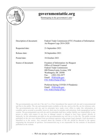
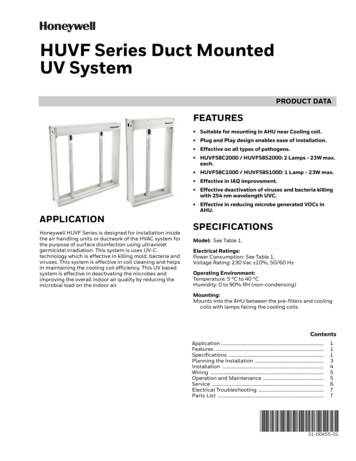
HUVF Series Duct MountedUV SystemPRODUCT DATAFEATURES Suitable for mounting in AHU near Cooling coil. Plug and Play design enables ease of installation. Effective on all types of pathogens. HUVF58C2000 / HUVF58S2000: 2 Lamps - 23W max.each. HUVF58C1000 / HUVF58S1000: 1 Lamp - 23W max. Effective in IAQ improvement. Effective deactivation of viruses and bacteria killingwith 254 nm wavelength UVC. Effective in reducing microbe generated VOCs inAHU.APPLICATIONHoneywell HUVF Series is designed for installation insidethe air handling units or ductwork of the HVAC system forthe purpose of surface disinfection using ultravioletgermicidal irradiation. This system is uses UV-Ctechnology which is effective in killing mold, bacteria andviruses. This system is effective in coil cleaning and helpsin maintaining the cooling coil efficiency. This UV basedsystem is effective in deactivating the microbes andimproving the overall indoor air quality by reducing themicrobial load on the indoor air.SPECIFICATIONSModel: See Table 1.Electrical Ratings:Power Consumption: See Table 1.Voltage Rating: 230 Vac 10%, 50/60 HzOperating Environment:Temperature: 5 C to 40 CHumidity: 0 to 90% RH (non-condensing)Mounting:Mounts into the AHU between the pre-filters and coolingcoils with lamps facing the cooling coils.ContentsApplication .Features .Specifications .Planning the Installation .Installation .Wiring .Operation and Maintenance .Service .Electrical Troubleshooting .Parts List .111345567731-00455-01
HUVF SERIES DUCT MOUNTED UV SYSTEMTable 1. HUVF Series Models.Weight:Shipping Weight:Single Lamp: 8.6 kgDual Lamp: 13 kgInstalled Weight:Single Lamp: 5 kgDual Lamp: 8 kgModelLampLamp Type Quantity Unit Wattage125 W1000 CFM(1700 m3/hr)HUVF58C2000250 W2000 CFM(3400 m3/hr)HUVF58S1000125 W1000 CFM(1700 m3/hr)250 W2000 CFM(3400 m3/hr)HUVF58C1000RegularDimensions:See Fig. 1. and Fig. 2.Lamp Length: 500 3 mmLamp Diameter: 15 mmShatterproofHUVF58S2000Lamp Connector: 4 PinCapacityLamp Wattage: 23 W102.4 mmLamp Current: 425 mA665.00 mmLamp Life: 12,000 hoursWavelength: 253.7 nm610.0 mmCumulative Average Intensity: 4647 μW/cm2, usingregular lamps under standard conditions.Ballast Type: High frequency electronicRepair Parts: See Table 2.Regulatory Approvals: CE, RoHSFig. 1. Dual lamp HUVF Series dimensions.IMPORTANTThis symbol on our product shows a crossed-out“wheelie-bin” as required by law regarding theWaste of Electrical and Electronic Equipment(WEEE) disposal. This indicates your responsibilityto contribute in saving the environment by properdisposal of this Waste, i.e. do not dispose of thisproduct with your other wastes. To know the rightdisposal mechanism please check the applicablelaw.350.0 mm610.0 mm102.4 mmFig. 2. Single lamp HUVF Series dimensions.31-00455—012
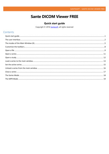
HUVF SERIES DUCT MOUNTED UV SYSTEMPLANNING THEINSTALLATIONChoosing a Mounting PositionCAUTIONEquipment Damage Hazard.NOTICE: Read the maintenance instructions before opening theappliance. Appliances that are obviously damaged must not beoperated. UV-C BARRIERS bearing the ULTRAVIOLET RADIATIONhazard symbol should not be removed. Do not operate UV-C LAMPS outside of the appliance.Ultraviolet light can cause color shift or surfacedegradation and sometimes structural degradationof non-metallic components. Select mountinglocation that prevents exposure to plastic flexibleduct components, polyurethane foam insulationmaterial, rubber hoses, wire insulation, etc. Ifmounting options are limited, items above shouldbe protected with ultraviolet resistant material suchas aluminum foil, aluminum duct tape, or metallicshields or the equivalent.The HUVF Series is used in forced air heating, cooling, orventilating systems. The system is mounted in the airhandling unit (AHU) or ductwork where there are coolingcoils or other surfaces that require ultraviolet treatment.When used in an AHU, the installation shall be donebetween the pre-filters and cooling coil in such a way thatthe lamps are facing towards the cooling coil.Detail ArrangementHUVF SeriesAIR INAIR OUTBlowerCooling CoilPre Filter/F58 Series EACFig. 3. HUVF positioning inside AHU.Constructing the ArrayMultiple systems can be nut and bolted to each other,either side by side or on top of other, to fill the cross sectionof the ductwork or air-handling unit where the UV system isbeing installed. If each system is individually supported bythe array support structure it is not necessary to connectthe systems to each other. The system can be connected toeach other as shown in the diagram below. Two or moresystems can be connected side by side, and when requiredmultiple rows can be placed on top of each other.The male and female connectors are used for powering thesystems. A common 230 Vac single phase power sourceshall be used for powering the array. The power shall not beturned 'ON' until all the mechanical fitment is finished,refer to WIRING section at the end of installation for mainspower connection.Fig. 4. Array detail view.331-00455—01
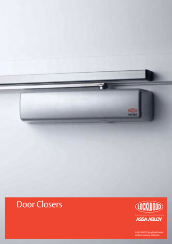
HUVF SERIES DUCT MOUNTED UV SYSTEMPower ConnectionMMMMTo adjacent unitFFMMMMFFFig. 5. Array interconnections.Constructing Array SupportStructureWARNINGUV Light Hazard.Harmful to bare skin and eyes.Can cause temporary or permanent loss of vision.Do not look at the UV lamp when lighting is on. Useindicator light on the ballast to check status. Inorder to prevent exposure to UV light, before repairof any parts of HVAC system, shut off power supplyto UV system. Do not install in a position where UVlamp is visible during normal operation of HVACequipment.WARNINGConstruction Collapse Hazard.Can cause personal injury or equipment damage.Provide adequate structural support to preventarray collapse. Support each unit with externalstructural elements across both top and bottom andadd cross supports, as needed.Provide adequate array support to prevent collapse: Provide minimum of external structural supportacross the top and bottom of each unit. Provide cross supports, as needed.CROSS SUPPORTSATTACHED TO DUCT FLANGEINSTALLATIONWhen Installing This Product AIR HANDLERDUCT FLANGE1.2.3.4.M134575.Fig. 6. Array support structure.31-00455—014The UV system is designed only for use inside AirHandling Units (AHU) and Air ducts. The units mustnot be used in any other location or manner. Themanufacturer will not be responsible for the performance of the system or any hazard to health by itsuse in an unintended manner.The UV system must be installed inside the AHU or airduct. An interlock switch to turn off the UV systemshould be provided during installation that turned offthe UV system in the event the AHU is opened oraccessed to prevent exposure to humans.Proper PPE and UV eye protection to be used duringinstallation of the system, UV rays are harmful to thehuman skin and eyes, care must be taken to ensureno direct exposure.Testing of lamps other than once installed inside anAHU fitted with an interlock switch should only bedone inside custom built fully enclosed test equipment.The installation, service and maintenance of the system must be carried out by the qualified personnel ofauthorized representative.
HUVF SERIES DUCT MOUNTED UV SYSTEMConnect the LampsMERCURY NOTICEThis device contains mercury in the sealedultraviolet bulb(s). Do not place your used bulb(s) inthe trash. Dispose of properly.WARNINGBreakable Glass Hazard.Can cause personal injury.Be careful when inserting bulb(s) into lamp base.Wear protective gloves when handling the bulb(s).Make sure that the UV lamp is connected properly to the4-pin holder and is fixed in the clamps provided on thereflector as shown in Fig. 7 below.123Fig. 7. Bulb connection.WIRING6.WARNINGPower InputAdjacent SystemMain power supply must be secured withinterlock on the AHU door.The electrical supply circuit connected to this UVappliance must be routed through an electricalinterlock switch placed on the HVAC system ductaccess panels and doors to prevent accidental UVexposure when servicing the air ducts orequipment. Interlock shall break all supplyconductors.3.4.5.FAdjacentSystemHUVF58C1000 / HUVF58C2000HUVF58S1000 / HUVF58S2000F Female ConnectorFig. 8. Power connection to HUVF.OPERATION ANDMAINTENANCENOTICE: Service of the product to be done by authorizedrepresentative only Operated and serviced by qualified personnel No interlocks under any circumstance are defeated All safety measures recommended are followed asprescribed Provided all control measures are implemented at theuser site for safety as per the Risk analysis document. Any internal part of the assembly shall not be removedfor independent use for other applications.Power Connections2.MMM Male Connector Power supply wiring system shall provide adisconnect switch for all poles. Assure all wiring complies with local codes andordinances. Wire the UV system directly to the correct voltageand frequency electrical source. See Fig. 8. Install extension box, with cover, for all externalplugs and wiring connections. This appliance incorporates an earth connectionfor functional purposes only.1.Install box and cover over power connector on opposite end of each row.Decide which end of the installed array is most accessible for wiring.Cut off the plastic connector for each row of aircleaners on the end selected.Install a extension box to the end of each row of aircleaners.Connect power and ground leads to each row of aircleaners.Install cover on each box.During normal operation make sure that the electricalsupply circuit connected to this UV appliance must berouted through an electrical interlock switch placed on theHVAC system duct access panels and doors to preventaccidental UV exposure when servicing the air ducts orequipment” or equivalent. “Interlock shall break all supplyconductors.531-00455—01
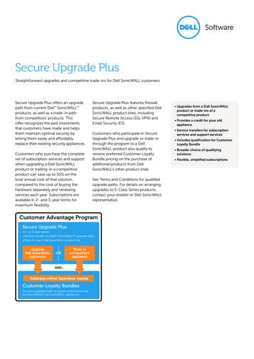
HUVF SERIES DUCT MOUNTED UV SYSTEMfixture clamps. Connect the new lamp in the 4-pin holderand fix the lamp in the SS clamps. Refer to Fig. 3 in theINSTALLATION section.During normal operation the lamps need to be cleanedonce or twice in a month to make sure that there is no dustaccumulation on the lamp surface. This cleaning can bedone by normal wiping cloth or tissue paper. Make surethat the lamp mounted on the reflector clips is tightenough so that it remains in the same position before andafter cleaning.Ballast ReplacementRefer to internal wiring diagrams.Do not pour / splash / spill water on the system and lampsduring the coil cleaning. In case of accidental spillage ofwater on the system make sure that the system is wipedwith a dry cloth to remove the water droplets. Do not switchON the UV system immediately, instead run the blower andthe HVAC system for some time (15-20 minutes) and thenswitch ON the UV system.Connectwell ConnectorFMMReplace as per lamp life issued in the documentation.BALLASTVEGO Connector4PinHolderSERVICEFig. 9. Wiring diagram for HUVF58C1000 andHUVF58S1000.Lamp ReplacementConnectwell ConnectorFWARNINGMVEGO ConnectorBreakable Glass Hazard.Can cause personal injury.Be careful when inserting bulb(s) into lamp base.Wear protective gloves when handling the bulb(s).MBALLAST4PinHolderMERCURY NOTICEFig. 10. Wiring diagram for HUVF58C2000 andHUVF58S2000.This device contains mercury in the sealedultraviolet bulb(s). Do not place your used bulb(s) inthe trash. Dispose of properly.Disconnect the line, neutral, earthing wire and lamp wiresfrom the ballast making note of the color code and positionof each wire. Back out the screws and remove the oldballast from the L plate.The UV lamps are rated for 12,000 hours of germicidaleffectiveness. The visible blue light will continue toilluminate but does not have any germicidal effectiveness.Bulbs must be replaced on schedule for the system tofunction properly.After removing the old ballast place new ballast on the Lplate and replace the mounting screws. Reconnect thepower and lamp cable wires as per color coding. Ballastreplacement is complete.IMPORTANTUse only Honeywell replacement lamps. Use ofreplacement lamps from other manufacturersvoids the warranty. See Table 2 for replacementlamp part numbers.ELECTRONIC BALLAST FOR UV LAMPSFor replacing the lamp(s) on the HUVF series firstdisconnect the power of the system. Remove the 4-pinholder on top of the lamp by pulling the lamp out of theFig. 11. Ballast Wiring.31-00455—014PinHolder6
HUVF SERIES DUCT MOUNTED UV SYSTEMELECTRICALTROUBLESHOOTINGTroubleshooting ProcedureWARNINGThe power supply to the system is connected using plugand play connector arrangement. Make sure that properPPE are used before start of any testing. Please note thatUV is harmful to human being and hence the system musthave interlock with the access door, so that when theaccess door is opened the system power supply will cut. Allthe systems installed inside the AHU will be powered up bythe single power cable. Please disconnect the power supplybefore servicing the unit.Tools and EquipmentCheck the input power cable looping using continuitytester and confirm that all the looping wires showcontinuity during power off condition. Make sure thatinterlock is in place once the servicing is completed. Oncethe access door is closed, switch ON the power supply sothat system starts working again.Electric Shock Hazard.Can cause personal injury or equipment damage.The following procedures expose hazardous liveparts and are for use only by qualified personnel.Disconnect power between checks and proceedcarefully.Tools to be used for electrical troubleshooting: Continuity tester. PPE KitPARTS LISTTable 2. HUVF Parts 2000LampHUVL58C0000HUVL58S0000Lamp VB58020007HolderHUVB58K100031-00455—01
HUVF SERIES DUCT MOUNTED UV SYSTEMHoneywell Building TechnologiesHoneywell International (India) Pvt. Ltd.1120-21, 11th Floor, Tower A, DLF TowerJasola District CentreJasola, NEW DELHI, 110025, India1-800-103-4761Honeywell Building TechnologiesHoneywell GmbHBöblinger Strasse 1771101 Schönaich, GermanyPhone 49 (0) 7031 637 01Fax 49 (0) 7031 637 740buildings.honeywell.comcustomer.honeywell.com U.S. Registered Trademark 2020 Honeywell International Inc.31-00455—01 M.S. 11-20Printed in United States
Power Connections 1. Decide which end of the inst alled array is most acces-sible for wiring. 2. Cut off the plastic connector for each row of air cleaners on the end selected. 3. Install a extension box to the end of each row of air cleaners. 4. Connect power and ground leads to each row of air cleaners. 5. Install cover on each box. 6.