Transcription
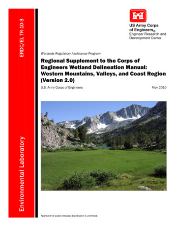
ERDC/EL TR-10-3Wetlands Regulatory Assistance ProgramRegional Supplement to the Corps ofEngineers Wetland Delineation Manual:Western Mountains, Valleys, and Coast Region(Version 2.0)Environmental LaboratoryU.S. Army Corps of EngineersApproved for public release; distribution is unlimited.May 2010
Wetlands Regulatory Assistance ProgramERDC/EL TR-10-3May 2010Regional Supplement to the Corps of EngineersWetland Delineation Manual: WesternMountains, Valleys, and Coast Region(Version 2.0)U.S. Army Corps of EngineersU.S. Army Engineer Research and Development CenterEnvironmental Laboratory3909 Halls Ferry RoadVicksburg, MS 39180-6199Final reportApproved for public release; distribution is unlimited.Prepared forHeadquarters, U.S. Army Corps of EngineersWashington, DC 20314-1000
ERDC/EL TR-10-3Abstract: This document is one of a series of Regional Supplements tothe Corps of Engineers Wetland Delineation Manual, which providestechnical guidance and procedures for identifying and delineating wetlands that may be subject to regulatory jurisdiction under Section 404 ofthe Clean Water Act or Section 10 of the Rivers and Harbors Act. Thedevelopment of Regional Supplements is part of a nationwide effort toaddress regional wetland characteristics and improve the accuracy andefficiency of wetland-delineation procedures. This supplement is applicable to the Western Mountains, Valleys, and Coast Region, which consistsof portions of 12 states: Arizona, California, Colorado, Idaho, Montana,Nevada, New Mexico, Oregon, South Dakota, Utah, Washington, andWyoming.DISCLAIMER: The contents of this report are not to be used for advertising, publication, or promotional purposes.Citation of trade names does not constitute an official endorsement or approval of the use of such commercial products.All product names and trademarks cited are the property of their respective owners. The findings of this report are not tobe construed as an official Department of the Army position unless so designated by other authorized documents.DESTROY THIS REPORT WHEN NO LONGER NEEDED. DO NOT RETURN IT TO THE ORIGINATOR.ii
ERDC/EL TR-10-3iiiContentsFigures and Tables .viPreface .ix1Introduction. 1Purpose and use of this regional supplement . 1Applicable region and subregions . 3Physical and biological characteristics of the region . 7Northwest Forests and Coast (LRR A) . 8Rocky Mountain Forests and Rangeland (LRR E) . 8Sierra Nevada Mountains (MLRA 22A) . 9Southern Cascade Mountains (MLRA 22B). 10Arizona and New Mexico Mountains (MLRA 39) . 10Black Hills (MLRA 62) . 10Types and distribution of wetlands. 11General . 11Irrigated wetlands . 152Hydrophytic Vegetation Indicators . 17Introduction . 17Guidance on vegetation sampling and analysis . 20Definitions of strata . 22Sampling wetland non-vascular plants . 22Seasonal considerations and cautions . 24Hydrophytic vegetation indicators . 24Procedure . 27Indicator 1: Rapid test for hydrophytic vegetation . 28Indicator 2: Dominance test . 28Indicator 3: Prevalence index . 30Indicator 4: Morphological adaptations . 33Indicator 5: Wetland non-vascular plants . 343Hydric Soil Indicators . 35Introduction . 35Concepts . 36Iron and manganese reduction, translocation, and accumulation . 36Sulfate reduction . 37Organic matter accumulation . 37Cautions . 38Procedures for sampling soils . 39Observe and document the site . 39Observe and document the soil . 41
ERDC/EL TR-10-3ivUse of existing soil data . 43Soil surveys . 43Hydric soils lists . 44Hydric soil indicators . 44All soils . 46Indicator A1: Histosol . 46Indicator A2: Histic Epipedon . 47Indicator A3: Black Histic . 48Indicator A4: Hydrogen Sulfide . 49Indicator A11: Depleted Below Dark Surface . 49Indicator A12: Thick Dark Surface . 51Sandy soils. 52Indicator S1: Sandy Mucky Mineral . 52Indicator S4: Sandy Gleyed Matrix . 53Indicator S5: Sandy Redox. 53Indicator S6: Stripped Matrix . 55Loamy and clayey soils . 56Indicator F1: Loamy Mucky Mineral . 56Indicator F2: Loamy Gleyed Matrix . 57Indicator F3: Depleted Matrix . 57Indicator F6: Redox Dark Surface . 59Indicator F7: Depleted Dark Surface. 60Indicator F8: Redox Depressions . 61Hydric soil indicators for problem soils . 62Indicator A10: 2 cm Muck . 62Indicator TF2: Red Parent Material . 63Indicator TF12: Very Shallow Dark Surface . 644Wetland Hydrology Indicators . 65Introduction . 65Growing season . 67Wetland hydrology indicators. 69Group A – Observation of Surface Water or Saturated Soils . 71Indicator A1: Surface water . 71Indicator A2: High water table . 72Indicator A3: Saturation . 73Group B – Evidence of Recent Inundation . 74Indicator B1: Water marks . 74Indicator B2: Sediment deposits . 75Indicator B3: Drift deposits . 76Indicator B4: Algal mat or crust . 77Indicator B5: Iron deposits. 77Indicator B6: Surface soil cracks. 79Indicator B7: Inundation visible on aerial imagery . 79Indicator B8: Sparsely vegetated concave surface . 80Indicator B11: Salt crust . 81Indicator B13: Aquatic invertebrates . 82Indicator B9: Water-stained leaves . 84Indicator B10: Drainage patterns. 85Group C – Evidence of Current or Recent Soil Saturation . 86Indicator C1: Hydrogen sulfide odor. 86
ERDC/EL TR-10-3vIndicator C3:Indicator C4:Indicator C6:Indicator C2:Indicator C9:Oxidized rhizospheres along living roots. 87Presence of reduced iron . 88Recent iron reduction in tilled soils . 89Dry-season water table . 90Saturation visible on aerial imagery . 91Group D – Evidence from Other Site Conditions or Data . 92Indicator D1: Stunted or stressed plants . 92Indicator D2: Geomorphic position . 93Indicator D3: Shallow aquitard . 94Indicator D5: FAC-neutral test . 95Indicator D6: Raised ant mounds . 96Indicator D7: Frost-heave hummocks . 975Difficult Wetland Situations in the Western Mountains, Valleys, and Coast Region . 98Introduction . 98Problematic hydrophytic vegetation . 99Description of the problem . 99Procedure . 99Problematic hydric soils . 109Description of the problem . 109Soils with faint or no indicators . 109Soils with relict hydric soil indicators . 111Procedure . 112Wetlands that periodically lack indicators of wetland hydrology . 115Description of the problem . 115Procedure . 116Wetland/non-wetland mosaics .122Description of the problem . 122Procedure . 123References. 125Appendix A: Glossary . 129Appendix B: Point-Intercept Sampling Procedure for Determining HydrophyticVegetation . 136Appendix C: Data Form . 138Report Documentation Page
ERDC/EL TR-10-3Figures and TablesFiguresFigure 1. Generalized map of the Western Mountains, Valleys, and Coast Region. 4Figure 2. Plant list regional boundaries currently used by the U.S. Fish and WildlifeService, National Wetlands Inventory, in the Western Mountains, Valleys, and CoastRegion. 26Figure 3. Divergent slopes disperse surface water, whereas convergent slopesconcentrate water . 41Figure 4. At the toe of a hill slope, the gradient is only slightly inclined or nearly level . 41Figure 5. Example of a Histosol, in which muck is greater than 3 ft (0.9 m) thick. . 47Figure 6. In this soil, the organic surface layer is about 9 in. (23 cm) thick. . 48Figure 7. Black organic surface layer greater than 11 in. (28 cm) thick. . 48Figure 8. In this soil, a depleted matrix starts immediately below the black surface layer atapproximately 11 in. (28 cm). . 50Figure 9. Deep observations may be necessary to identify the depleted or gleyed matrixbelow a thick, dark surface layer . 51Figure 10. The mucky modified sandy layer is approximately 3 in. (7.5 cm) thick. 52Figure 11. In this example, the gleyed matrix begins at the soil surface. 53Figure 12. Redox concentrations in sandy soil material. . 54Figure 13. Stripped areas form a diffuse, splotchy pattern in this hydric sandy soil. . 55Figure 14. Location of MLRAs 1, 2, 4A, and 4B in LRR A. 56Figure 15. This soil has a gleyed matrix in the lowest layer, starting about 7 in. (18 cm)from the soil surface . 57Figure 16. Example of indicator F3, in which redox concentrations extend nearly to thesurface. . 58Figure 17. This soil has a depleted matrix with redox concentrations in a low-chromamatrix. 58Figure 18. Redox features can be small and difficult to see within a dark soil layer. . 59Figure 19. Redox depletions are scattered within the darker matrix . 60Figure 20. In this example, the layer of redox concentrations begins at the soil surfaceand is slightly more than 2 in. (5 cm) thick. 61Figure 21. A layer of muck occurs in the upper 6 in. (15 cm) of this soil. 63Figure 22. Wetland with surface water present. . 71Figure 23. High water table observed in a soil pit. 72Figure 24. Water glistens on the surface of a saturated soil sample. 73Figure 25. Water mark on a boulder .74Figure 26. Silt deposit left after a recent high-water event forms a tan coating on thesetree trunks. 75Figure 27. Drift deposit on the upstream side of a sapling in a floodplain wetland. . 76Figure 28. Deposit of green algae in a seasonally inundated Juncus marsh. . 77vi
ERDC/EL TR-10-3Figure 29. Dark-colored material is benthic microflora consisting of blue-green and greenalgae in a hypersaline intertidal marsh. 77Figure 30. Dried crust of blue-green algae on the soil surface. . 77Figure 31. Iron sheen on the water surface may be deposited as an orange or yellow crustafter dewatering. . 78Figure 32. Iron deposit in a dewatered channel. . 78Figure 33. Surface soil cracks in a seasonally ponded wetland. . 79Figure 34. Aerial view showing inundated areas. 80Figure 35. A sparsely vegetated, seasonally ponded depression. . 81Figure 36. A hard salt crust in a dry temporary pool. 82Figure 37. A hard salt crust on plant stems and the soil surface in a seasonally pondedarea. 82Figure 38. Shells of aquatic snails in a seasonally ponded fringe wetland. 83Figure 39. Carapaces of tadpole shrimp (Triops sp.) and clam shrimp (Leptestheriacompleximanus) in dried sediments of an ephemeral pool . 83Figure 40. Water-stained leaves in a temporarily ponded depression. 84Figure 41. Drainage pattern in a slope wetland. . 85Figure 42. Vegetation bent over in the direction of water flow across a stream terrace. 86Figure 43. Iron-oxide plaque on a living root. Iron also coats the channel or pore fromwhich the root was removed. . 87Figure 44. This soil has many oxidized rhizospheres associated with living roots. . 88Figure 45. When alpha, alpha-dipyridyl is applied to a soil containing reduced iron, apositive reaction is indicated by a pink or red coloration to the treated area. . 89Figure 46. Redox concentrations in the tilled surface layer of a recently cultivated soil. . 90Figure 47. Aerial photograph of an agricultural field with saturated soils indicated bydarker colors. . 92Figure 48. Stunted corn due to wet spots in an agricultural field. . 93Figure 49. Certain geomorphic positions, such as this estuarine fringe, are evidence ofwetland hydrology. . 94Figure 50. Procedure and example of the FAC-neutral test . 95Figure 51. Raised ant mounds in a Willamette Valley, OR, wetland. . 96Figure 52. Frost-heave hummocks. . 97Figure 53. Example of sparse and patchy plant cover in a wetland. 102Figure 54. Mature Populus deltoides stand on an elevated floodplain terrace with xericunderstory on the South Fork of the Shoshone River, Wyoming. . 103Figure 55. This soil exhibits colors associated with reducing conditions. . 114Figure 56. The same soil as in Figure 55 after exposure to the air and oxidation hasoccurred. . 114Figure A1. Illustration of values and chromas that require 2 percent or more distinct orprominent redox concentrations and those that do not, for hue 10YR, to meet thedefinition of a depleted matrix .132Figure A2. For hydric soil determinations, a gleyed matrix has the hues and chromaidentified in this illustration with a value of 4 or more .135vii
ERDC/EL TR-10-3TablesTable 1. Sections of the Corps Manual replaced by this Regional Supplement forapplications in the Western Mountains, Valleys, and Coast Region . 2Table 2. Comparison of general landscape characteristics between the Arid West Regionand the Western Mountains, Valleys, and Coast Region. 6Table 3. Selected references to additional vegetation sampling approaches that could beused in wetland delineation. . 21Table 4. Bryophyte species that are highly associated with wetlands in western hemlockforests in the Pacific Northwest. . 23Table 5. Example of the selection of dominant species by the 50/20 rule anddetermination of hydrophytic vegetation by the dominance test. . 30Table 6. Example of the prevalence index using the same data as in Table 5. . 32Table 7. Proportion of sample that is fibers visible with a hand lens. . 38Table 8. Determination of degree of decomposition of organic materials. . 39Table 9. Minimum thickness requirements for commonly combined indicators in theWestern Mountains, Valleys, and Coast Region. . 45Table 10. Example of a soil that is hydric based on a combination of indicators F6 and F3. 45Table 11. Example of a soil that is hydric based on a combination of indicators F6 and S5. . 46Table 12. Wetland hydrology indicators for the Western Mountains, Valleys, and CoastRegion. 70Table A1. Tabular key for contrast determinations using Munsell notation.130viii
ERDC/EL TR-10-3PrefaceThis document is one of a series of Regional Supplements to the Corpsof Engineers Wetland Delineation Manual. It was developed by theU.S. Army Engineer Research and Development Center (ERDC) at therequest of Headquarters, U.S. Army Corps of Engineers (USACE), withfunding provided through the Wetlands Regulatory Assistance Program(WRAP). This is Version 2.0 of the Western Mountains, Valleys, and CoastRegional Supplement; it replaces the “interim” version, which waspublished in April 2008.This document was developed in cooperation with the Western Mountains, Valleys, and Coast Regional Working Group, whose memberscontributed their time and expertise to the project over a period of manymonths. Working Group meetings were held in Portl
ERDC/ EL TR-10-3 _ _ Wetlands Regulatory Assistance Program Regional Supplement to the Corps of Engineers Wetland Delineation Manual: Western Mountains, Valleys, and Coast Region