Transcription
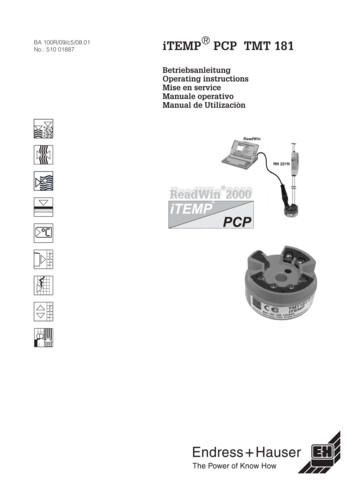
BA 100R/09/c5/08.01No.: 510 01887iTEMP PCP TMT 181BetriebsanleitungOperating instructionsMise en serviceManuale operativoManual de Utilizaciòn
ContentsEnglishContents1 Safety notes . 211.1 Correct use . 211.2 Installation, commissioning and operation.211.3 Operational safety. 211.4 Returns. 211.5 Safety pictograms and symbols . 212 Identification. 222.1 Unit identification . 222.2 Delivery contents . 223 Function and system construction .233.1 Function . 233.2 Measurement system. 234 Installation . 234.1 Installation conditions. 234.2 Installation . 235 Wiring . 255.1 Overview . 255.2 Measurement unit connection. 256 Operation . 276.1 Short form instructions (SETUP). 276.2 Communication . 277 Commissioning . 287.1 Installation check . 287.2 Commissioning . 287.3 Function check. 288 Maintenance . 299 Accessories . 2910 Fault finding. 2910.1 Spare parts. 2910.2 Repair concept and disposal . 2910.3 Fault finding and repairs . 2911 Technical Data. 3112 Appendix. 3413 Catch phrases . 3520
Safety notes1 Safety notesSafe and secure operation of the head transmitter can only be guaranteed if theoperating instructions and all safety notes contained are read, understood andfollowed.1.1 Correct use The unit is a universal, presettable temperature transmitter for resistancethermometer (RTD), thermocouple (TC) as well as resistance and voltage sensors.The unit is constructed for mounting in a connection head (form B) and a fieldhousing. The user cannot be held responsible for damage caused by misuse of the unit. Separate Ex documentation, is contained in this operating manual, formeasurement systems that are to mounted in hazardous areas. The installationconditions as well as the connection values indicated in these instructions mustbe completely followed!EnglishCorrect use1.2 Installation, commissioning and operationInstallation,commissioning andoperationThe unit is constructed using the most up-to-date production equipment andcomplies to the safety requirements of the EU guidelines. However. If it is installedincorrectly or is misused then certain application dangers can occur. Installation,wiring and maintenance of the unit must only be done by trained skilled personnelwho are authorised to do so by the plant operator. These skilled staff must have readand understood these instructions and must also follow them to the letter. The plantoperator must make sure that the measurement system has been correctly wired tothe connection schematics.1.3 Operational safetyOperational safetyHazardous areasWhen installing the unit in a hazardous area the national safety requirements must bemet. Make sure that all personnel are trained in these areas. The measurement andsafety values must be followed in all these installations.Technical advancementThe manufacturer reserves the right to change the technical data without notification ifthis advances the technical development. Details regarding the validity and furtherexpansions to these instructions can be obtained from your nearest sales office.1.4 ReturnsReturnsWhen returning the unit for repair please add a description of both the fault and theapplication.On transport damage please contact both the supplier and shipping agent.1.5 Safety pictograms and symbolsSafety pictogramsand symbolsSafe and reliable operation of this unit can only be guaranteed if the safety hints andwarnings in these operating instructions are followed. The safety hints in theseinstructions are highlighted using the following symbols.Hint:This symbol indicates activities and actions that, if not followed correctly, could havean indirect influence on the unit operation or could lead to an unforeseen unit reaction.Attention:This symbol indicates activities and actions that, if not followed correctly, could leadto faulty unit operation or even damage to the unit.21
IdentificationHazardous area, certified equipment:If this character can be seen on the unit then it may be operated in hazardous areas.Non-hazardous areas:This symbol identifies the non-hazardous areas in these instructions.Units that operate in the non-hazardous areas but that are connected to thehazardous areas must also be certified.2 Identification2.1 Unit identificationUnit identificationHead transmitter legend plateOrder code (example)Identification for hazardous area use(only on Ex certified units)CE-marks, conformity descriptionThe unit has been manufactured using up-to-date production equipment and has leftour works in perfect and safe condition. It complies with the safety requirements toEN 61 010.The unit described in these instructions therefore fulfils the legal requirements set bythe EU guide lines. The manufacturer confirms a positive completion of all tests byfitting the unit with a CE mark.2.2 Delivery contentsDelivery contentsThe delivery contents of a temperature head transmitter are as follows: Head transmitter Installation screws and springs Operating instructions ATEX-operating instructions for use in hazardous areasHint!Please take note of the head transmitter accessories in chapter 9.22
Function and system construction3 Function and system construction3.1 FunctionFunctionElectronic monitoring and transformation of various input signals into an analogueoutput signal in industrial temperature measurement. The head transmitter is mountedin a connection head form B or separated from the sensor in field housing. Setting upof the head transmitter is done using a PC and setting up software. The configurationkit is required for setting up the head transmitter.3.2 Measurement systemMeasurementsystemTransforming the following input signals: Resistance thermometers (RTD) and resistance sensors(in 2-,3- or 4-wire connection systems) Thermocouples (TC) and voltage sensors into a scalable analogue output signal (4.20 mA or 20.4 mA).Fault monitoring of: Measurement range override or undercut Sensor breakage and short circuit [1]The head transmitter is set up using a PC and the PC setting up programme togetherwith the configuration kit. The kit can be obtained as a unit accessory.Application in hazardous areas is certified to ATEX II 1 GEEx ia IIC T4/T5/T6.4 Installation4.1 Installation conditionsInstallationconditions When installing and operating the unit please take note of the allowable ambienttemperature (see chapter 11: Technical data). When operating in hazardous areas please take note and operate within the limitsset in the certification (see chapter 11: Technical data).DimensionsThe head transmitter dimensions can be found in Chapter 11: Technical data.Installation point Sensor connection head to DIN 43 729 Form B Field housingInstallation angleThere are no limits as to the angle on installation.4.2 InstallationInstallationFor installation proceed as follows:Installing in a sensor connection head to DIN 43 729 Form B (Fig. 4.1) Feed the sensor inset cables (Pos. 5) through the central hole in the headtransmitter (Pos. 4). Place the installation springs (Pos. 3) onto the screws (Pos. 2). Feed the installation screws (Pos. 2) through the holes in the head transmitter andthe holes in the sensor inset (Pos. 5). Fix both screws using the circlips (Pos. 6). Position the head transmitter in the connection head in such a way so that thecurrent output terminals (terminal 1 and 2) are towards the cable entry gland(Pos. 7). Fix the head transmitter (Pos. 4) and sensor inset (Pos. 5) into the connection head.[1] not for thermocouples (TC)23
InstallationInstallation in a field housing (Fig. 4.2) Feed the installation screws (Pos. 2) with installation springs (Pos. 3) through theholes in the head transmitter (Pos. 4). Fix these using the circlips (Pos. 5). Screw the head transmitter into the field housing using a screw driver.Attention:In order to avoid damaging the head transmitter do not over tighten the installationscrews.Pos.1: CoverPos.2:Installation screwsPos.3:Installation springsPos.4:Head transmitterPos.5:Sensor inset withconnection cablesPos.6:CirclipsPos:7:Cable glandFig. 4.1: Installation of head transmitter into aForm B sensor connection head.24Pos.1: CoverPos.2: Installation screwsPos.3: Installation springsPos.4: Head transmitterPos.5: CirclipsPos:6: Field housingFig. 4.2: Installation of head transmitter into afield housing
Wiring5 Wiring5.1 OverviewWiring overviewTerminal layoutPos.A: SETUP socket2-wire3-wire4-wireFig. 5.1: Head transmitter wiringMeasurement unitconnection5.2 Measurement unit connectionAttention:Switch off power supply before opening the housing cover. Do not install or connectthe unit to mains power. If this is not followed parts of the electronic circuit will bedamaged. Sensors:Connect the sensor cables to the respective head transmitter terminals(Terminals 3 to 6) by following the wiring diagram (see fig. 5.1). Output signal and power supply:Open the PG cable gland on the head transmitter or field housing. Feed the cablethrough the opening in the PG cable gland and then connect the cable cores toterminals 1 and 2 according to the wiring diagram (see fig. 5.1). PC configuration (SETUP socket):Open the flap on the SETUP socket (Fig. 5.1, Pos. A) and connect the SETUPconnection cable.Hint:The screws on the terminals must be screwed up tightly. Head transmitterconfiguration during measurement operation is possible. There is no need todisconnect cables!Potential levelingHint:Please take note of the following when installing the head transmitter remotely in afield housing. The screen on the output (output signal 4.20 mA) must have the samepotential as the screen at the sensor connections!For an effective screening the cable screen must be widely connected to the fieldhousing. This can be achieved by connecting the cable screen to the specialEMC-PG13.5 cable gland.Open the field housing PG cable gland and connnect the screen of the output andsensor connection according to Fig. 5.2.25
WiringWhen using earthed thermocouples screening of theoutput cable (4 . 20 mA cable) is recommended.In plants with strong EMC problems screening of allcables with a low ohm connection to the transmitterhousing is aabbbbbbbbFig. 5.2: Screening onremote installation26
Operation6 Operation6.1 Short form instructions (SETUP)OperationPresettable parametersStandard settings(Quick-SETUP)- Sensor type (see Chap. 11 Techn. data)- Connection mode [1]- Units ( C/ F)- Measurement range start (see Chap. 11 Techn. data)- Measurement range end (see Chap. 11 Techn. data)Expanded settings- Cold junction compensation (internal/external) [2]- Compensation resistance (0.20 Ω) [3]- Fault condition reaction (see Chap. 11 Techn. data)- Output (analogue standard/inverse)- Damping (0.60 s)- Offset (-9.9 to 9.9 K)- Measurement point identification/TAGService functions- Simulation (on/off)6.2 CommunicationCommunicationThe head transmitter must be set up using a PC and configuration set. The followingpoints must be taken into account if trouble free setting up is to be achieved: Configuration software installation Connect the head transmitter to the PC using the connection cable from theconfiguration setConfiguration software installationSystem conditions- IBM PC or compatible computer (min. Pentium 166 MHz)- Windows 95/98/ME/NT4.0/2000- 64 MB RAM- min. 30 MB free memory on hard drive- CD-ROM drive- Screen resolution 800 x 600 Pixel- free serial interfaceRecommended minimumconfiguration- Pentium 400 MHz- 128 MB main RAM- 120 MB free hard drive memory- Screen resolution 1024 x 768 PixelInstallation startStart Windows1. Place installations-CD in the respective drive2. Start “Setup.exe” and follow the installation instructions3. If required the help/operating manual can be printed out once thesoftware has been successfully installed.Connecting the head transmitter to the PC using the configuration kitconnection cable1. Connect the SETUP connector of the interface cable to the SETUP socket in thehead transmitter (see chapter 5.2 Connecting measurement unit).2. Connect the RS232C connector to a free serial interface socket on the PC. In orderto achieve optimum connection tighten the RS232C connector screws to the PC.Hint:Configuration of the head transmitter can be done either under power e.g. usinga 9 Volt battery or in an installed condition during measurement operation.[1] 2-, 3-, or 4-wire connection[2] on TC-connection[3] on 2-wire connection27
Commissioning7 Commissioning7.1 Installation checkInstallation checkMonitor all connections making sure they are tight. In order to guarantee fault freeoperation the terminal screws must be tight onto the connection cables. The unit isnow ready for operation.7.2 CommissioningCommissioningOnce the power supply has been connected the head transmitter is operational.Setting up using the PC configuration softwareThe head transmitter left the factory with a default parameter configuration. If nocustomer specific configuration was mentioned on the order then the defaultparameter configuration is constructed as follows:SensorPt100 (RTD)Connection mode3-wireMeasurement range andunits0. 100 CHint:If a change has been made to the measurement point then the head transmitter canbe re-configured. In order to re-configure the parameters follow these instructions: Install the configuration software and make connection to the PC (see Chap. 6,Operation). For detailed operating instructions for the PC configuration software please read theonline documentation contained in the PC configuration software.Interactive setting up of the temperature transmitterCustomer specific linearisation and sensor matching is done using the SMC32.exe(Sensor Matching Calibration) configuration software. The SMC32.exe programmecalculates the linearisation coefficients X0 to X4, that need to be entered into the PCconfiguration software.7.3 Function checkFunction check28Measuring the analogue 4-20 mA output signal or following failure signals:Measurement rangeundercutlinear fall to 3.8 mAMeasurement range excesslinear rise to 20.5 mASensor break; sensor shortcircuit 3.6 mA or 21.0 mA selectable
Maintenance, accessories, fault finding8 MaintenanceMaintenanceThe head transmitter is maintenance free.9 AccessoriesAccessoriesConfiguration set for PC SETUP settings of the head transmitter:SETUP programme and PC serial interface cable (TTL/RS 232C).Order No.:TMT181A-VKHint:Please contact your supplier when ordering!10 Fault findingFault finding10.1 Spare partsHead transmitter installation set(4 screws, 6 springs, 10 circlips)Order No.:510 0111210.2 Repair concept and disposalDue to its construction the head transmitter cannot be repaired.Disposal:When disposing of the head transmitter please take note of the local disposalregulations.10.3 Fault finding and repairsTrouble shooting in generalFaultNo communicationCauseAction/cure2 wire connection incorrectRe-connect correctly (seeconnection diagram)No power supply to the 2 wireconnectionCheck the current loopPower supply to low ( 8 V)Check power supplyInterface cable defectiveCheck the interface cablePC-interface defectiveCheck the interface of your PCHead transmitter defectiveReplace head transmitter29
Maintenance, accessories, fault findingTrouble shooting on RTDs (Pt100/Pt500/Pt1000/Ni100)FaultCurrent( 3.6 mA or 21 mA)Incorrect or inaccuratemeasured valueCauseAction/cureSensor defectiveCheck sensorIncorrect RTD connectionConnect the cables correctly (seeconnection diagram)Incorrect 2 wire connectionConnect the cables correctly (seeconnection diagram) (Polarity)No power supply on the 2 wireconnectionCheck current loop; the supplyshould be 8 VIncorrect transmitter programming(number of wires)Change parameter ‘connectionmode’ (see chap. Operation)ProgrammingThermocouple set up (see chap.Operation). Change to RTDHead transmitter defectiveReplace head transmitterSensor is incorrectly installedReinstall sensor correctlyHeat dissipation via sensorMonitor sensor installationpositioningIncorrect transmitter programming(number of wires)Change parameter ‘connectionmode’Incorrect transmitter programming(Scale)Change scaleWrong RTD set upChange parameter ‘sensor type’Sensor connection (2 wire)Monitor sensor connectionSensor cable resistance notcompensated (2 wire)Compensate cable resistanceOffset incorrectly set upMonitor offsetTrouble shooting for thermocouple connection (TC)FaultCurrent( 3.6 mA or 21 mA)Incorrect or inaccuratemeasured value30CauseAction/cureIncorrect sensor connectionConnect the sensor correctly (seeconnection diagram) (Polarity)Sensor defectiveCheck sensorIncorrectly set upSensor type ‘RTD’ is set up. Set upthe correct thermocoupleIncorrect 2 wire connection (currentloop)Connect the cables correctly (seeconnection diagram)No power supply on the 2 wireconnectionCheck current loop; the supplyshould be 8 VHead transmitter defectiveReplace head transmitterSensor is incorrectly installedReinstall sensor correctlyHeat dissipation via sensorMonitor sensor installation positioningIncorrect transmitter programming(scale)Change scaleWrong thermocouple set upChange parameter ‘sensor type’Incorrect comparison set upSee chap. ‘Operation’ and‘Technical data’Offset incorrectly set upCheck offsetFault due to the thermo wire weldedto the well (interference voltagesincurred)Please use a sensor in which thethermo wire in not welded
Technical Data - Appendix11 Technical DataFunction and nic measurement and conversion of input signals in industrial temperaturemeasurement.Measurement systemThe temperature head transmitter is a two wire transmitter with an analogueoutput. It has measurement input for resistance thermometers (RTD) in2-, 3- or 4-wire connection, thermocouples and voltage transmitters. Setting up ofthe unit is done using the PC configuration kit.Resistance thermometer (RTD)TypeMeasurement rangesmin. rangePt100Pt500Pt1000-200 to 850 C-200 to 250 C-200 to 250 C-328 to 1562 F-328 to 482 F-328 to 482 F-60 to 180 C-60 to 150 C-60 to 150 C-76 to 356 F-76 to 302 F-76 to 302 F10 K (18 F)10 K (18 F)10 K (18 F)according to IEC 751Ni100Ni500Ni100010 K (18 F)10 K (18 F)10 K (18 F)according to DIN 43760Connection type2-, 3- or 4-wire connectioncable resistance compensation possible in the 2 wire system (0.20 Ω)Sensor cableresistancemax. 11 Ω per cableSensor current 0.6 mAResistance transmitter (Ω)TypeMeasurement rangemin. rangeResistance (Ω)10. 400 Ω10.2000 Ω10 Ω100 ΩMeasurement rangemin. rangeThermocouples (TC)TypeB (PtRh30-PtRh6)C (W5Re-W26Re)[3]D (W3Re-W25Re)[3]E (NiCr-CuNi)J (Fe-CuNi)K (NiCr-Ni)L (Fe-CuNi)[2]N (NiCrSi-NiSi)R (PtRh13-Pt)S (PtRh10-Pt)T (Cu-CuNi)U (Cu-CuNi)[2]MoRe5-MoRe41[1]0 to 1820 C0 to 2320 C0 to 2495 C-200 to 915 C-200 to 1200 C-200 to 1372 C-200 to 900 C-270 to 1300 C0 to 1768 C0 to 1768 C-200 to 400 C-200 to 600 C0 to 2000 C32 to 3308 F32 to 4208 F32 to 4523 F-328 to 1679 F-328 to 2192 F-328 to 2501 F-328 to 1652 F-454 to 2372 F32 to 3214 F32 to 3214 F-328 to 752 F-328 to 1112 F32 to 3632 F500 K (900 F)500 K (900 F)500 K (900 F)50 K (90 F)50 K (90 F)50 K (90 F)50 K (90 F)50 K (90 F)500 K (900 F)500 K (900 F)50 K (90 F)50 K (90 F)500 K (900 F)accord. to IEC 584 Part 1Cold junctioninternal (Pt100) or external (0.80 C)Cold junctionaccuracy 1KSensor current350 nAVoltage transmitters (mV)TypeMeasurement rangeMillivolt transmitter (mV) -10.100 mVmin. range5 mV[1] no reference[2] according to DIN 43710[3] according to ASTM E 98831
Technical Data - AppendixOutputOutput (analogue)Output signal4.20 mA, 20.4 mATransmission astemperature linear, resistance linear, voltage linearMax. load(Vpower supply - 8 V) / 0.022 ADigital filter1st degree0.8 sInput current required 3.5 mACurrent limit 23 mASwitch on delay4 s (during power up Ia 3.8 mA)Reply time1sFailure signal (fault monitoring)Measurement rangeundercutLinear drop to 3.8 mAExceedingmeasurement rangeLinear rise to 20.5 mASensor breakage; 3.6 mA or 21.0 mA can be set upSensor short circuit [1]Electrical connectionAccuracyPower supplyUb 8.35 V DC, polarity protectedGalvanic isolation(In/out)Û 3.75 kV ACAllowable rippleUss 5 V at Ub 13 V, fmax. 1 kHzReferenceconditionsCalibration temperature 23 C 5 KResistance thermometer (RTD)TypeMeasurement accuracy[2]Pt100, Ni100Pt500, Ni500Pt1000, Ni10000.2 K or 0.08%0.5 K or 0.20%0.3 K or 0.12%Resistance transmitter (Ω)TypeResistance (Ω)Measurement accuracy[2]Measurementrange 0.1 Ω or 0.08%10.400 Ω 1.5 Ω or 0.12%10.2000 ΩThermocouple (TC)TypeMeasurement accuracy[2]K, J, T, E, L, UN, C, DS, B, R MoRe5-MoRe41typ. 0.5 K or 0.08%typ. 1.0 K or 0.08%typ. 2.0 K or 0.08%Influence of the internalreference junctionPt100 DIN IEC 751 Cl. BVoltage transmitter (mV)TypeMeasurement accuracy[2]MeasurementrangeMillivolt transmitter (mV) 20 µV or 0.08%-10.100 mV[1] Not for thermocouple[2] % is related to the adjusted measurement range (the value to be applied is the greater)32
Technical Data - AppendixInfluence of powersupply 0.01%/V deviation from 24 V [1]Load influence 0.02%/100 Ω [1]Temperature driftResistive thermometer (RTD):Td (15 ppm/K max. meas. range 50 ppm/K preset meas. range) * ϑResistive thermometer (Pt100):Td (15 ppm/K range end value 200) 50 ppm/K preset meas. range) * ϑThermocouple (TC):Td (50 ppm/K max. meas. range 50 ppm/K preset meas. range) * ϑ ϑ Deviation of the ambient temperature according to reference junctionLong term stabilityApplication conditions 0.1 K/Year[2] or 0.05%/Year[2] [3]Installation conditionsInstallation angleNo limitInstallation areaConnection head accord. to DIN 43 729 Form B; field housingAmbient conditionsDimensionsAmbient temperature-40. 85 C (for Ex-areas see Ex-certification)Storage temperature-40. 100 CClimatic classTo EN 60 654-1, Class CMoisturecondensationAllowableIngress protectionIP 00 / IP 66 installedVibration protection4g / 2.150 Hz according to IEC 60 068-2-6EMC immunityInterference immunity and interference emission according toEN 61 326-1 and NAMUR NE21DimensionsDimensions in mmWeightapprox. 40 gMaterialsHousing: PCPotting: PURTerminalsCable up to max. 1.75 mm2 (secure screws)[1] All data is related to a measurement end value (FSD) of 20 mA[2] Under reference conditions[3] % is related to the adjusted measurement range (the value to be applied is the greater)33
Technical Data - AppendixTerminal connectionsPower supply and current outputSensor connectionDisplay and operatinglevelSETUP socket2-wire3-wireRemote operationConfiguration setPC configuration kitConfigurationUsing PC programmeInterfacePC interface connection cable TTL -/- RS 232 with plugConfigurableparametersSensor type and connection type, engineering units ( C/ F), measurement range,internal/external cold junction compensation, cable resistance compensation on2 wire connection, fault conditioning, output signal (4.20/20.4 mA), digital filter(damping), offset, measurement point identification (8 characters), outputsimulationCE markThe measurement system fulfills the requirements demanded by the EUregulations. The manufacturer acknowledges successful unit testing by addingthe CE mark.Ex certificationFor further details on the available Ex versions (ATEX, FM,CSA, etc.) contactyour respective sales organisation. All relevant data for hazardous areas can befound in separate Ex documentation. If required, please request copies fromyour sales organisation.Certification12 AppendixAppendixShort form instructions (SETUP)Presettable parametersStandard settings(Quick-SETUP)- Sensor type (see Chap. 11 Techn. data)- Connection mode [1]- Units ( C/ F)- Measurement range start (see Chap. 11 Techn. Data)- Measurement range end (see Chap. 11 Techn. Data)Expanded settings- Cold junction compensation (internal/external) [2]- Compensation resistance (0.20 Ω) [3]- Fault condition reaction (see Chap. 11 Techn. Data)- Output (analogue standard/inverse)- Damping (0.60 s)- Offset (-9.9 to 9.9 K)- Measurement point indentification/TAGService functions- Simulation (on/off)[1] 2-, 3-, or 4-wire connection[2] on TC-connection[3] on 2-wire connection344-wire
PCP TMT 181 Betriebsanleitung Operating instructions Mise en service Manuale operativo Manual de Utilizaciòn. . wiring and maintenance of the unit must only be done by trained skilled personnel . of the head transmitter is done using a PC and setting up software. The configuration kit is required for setting up the head transmitter.