Transcription
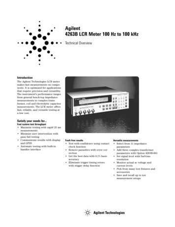
Agilent4287A RF LCR Meter1 MHz - 3 GHzTechnical Overview
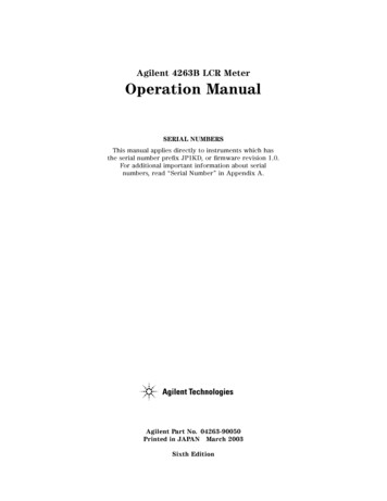
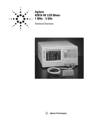
High-Speed RF LCR Meter Anticipating Next Generation Test NeedsThe Agilent 4287A is a high performance RF LCR meter best fit to production line testing of devices such asSMD inductors and EMI filters, where impedance testing at high frequencies is required.Signal-level monitor functionMonitors the test signal voltageor current applied to the deviceunder test.8.4 inch color LCD displaySelectable measurementparameters (4 parameters canbe displayed simultaneously)Small test head with 1m test cableExtension to an automatedcomponent handler withoutintroducing additional errorLAN interface For remote test controland fast data transferRdc (DC resistance)measurement functionFor contact checkNavigation keys and rotary knobSupport front panel operationwithout the mouse3.5 mm (female) test portExternal VGA output Display measurement resultson a larger VGA monitorOpto-isolated handler interface Easy integration with an automaticcomponent handler Highest throughput in automaticcomponent test handshakingExternal keyboard and mouse interface Easy to use by simplifyingmeasurement setup and programming2GPIB interface Controlled by external PC.(cannot control external devices)
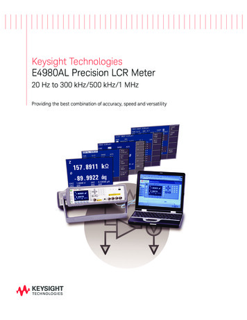
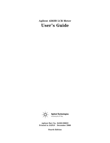
The 4287A greatly increasesmanufacturing testing efficiencywith fast measurement speeds(9 msec/point) and a statisticalanalysis function, among the otherpowerful functions, such as thebuilt-in comparator function. Inaddition, the 4287A improves uponthe measurement accuracy andimpedance measurement rangeof previous RF LCR meters. Theseimprovements are realized byadvanced techniques in analogcircuit design. The 4287A achievesbetter measurement repeatabilityand stability, even at the lowtest-signal levels required forSMD inductor testing.Setup display select menuSetup editorChanges can be made easilywith the mouse or navigation keysUser-friendly interfaceAn object-oriented user interfacethat is navigable using the mouse,panel keys or keyboard simplifiescomplicated measurement setupprocedures. Setups, including testfrequency, signal level (also whenusing list-sweep), and limits for themulti-function comparator, can beperformed and verified easily byediting the setup-tables. The setupeditor has eight page tables andcan store eight different setups.After the setup tables have beenestablished, the active measurementsetup can be chosen simply byselecting the corresponding number(1 through 8).8 page setup tablesFigure 1. List sweep setup displayKey specificationsTest frequency1 MHz - 3 GHz with 100 kHz resolution.With list-sweep, up to 32 points per sweep is available.Impedance parameters Z , θz (rad), θz (deg), Y , θy (rad), θy (deg), X, G, B, Ls, Lp, Cs, Cp, Rs, Rp, Q, DDisplay resolutions5 digitsTest signal levelV (open condition): 4.47 mVrms - 502 mVrms (447 mVrms when 1 GHz)I (short condition): 0.0894 mArms - 10 mArms (8.94 mArms when 1 GHz)Basic accuracy 1.0%Measurement range200 mΩ to 3 kΩ (@1 MHz, accuracy 10%)Measurement time9 msec per point (max. speed)Measurement terminal3.5 mm (female)Calibration and compensationOpen/short/load/low-loss capacitor calibration, fixture electrical lengthcompensation, open/short compensationRdc measurement functionFor contact check (on/off selectable)Data storage devicesAbout 18 Gbyte internal hard disk and 1.44 Mbyte floppy diskInterfaceGPIB, LAN (10base-T/100base-TX automatically switched), andOpto-isolated handler interface3
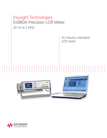
Improving Throughputand Quality In ProductionLine TestingAccurate impedancemeasurement using theRF I-V measurement methodThe 4287A uses the RF I-Vmeasurement method for measuringimpedance by measuring the currentflowing through a device under test(DUT) and the voltage applied acrossthe DUT. These measurements ofcurrent and voltage can be made overthe entire measurement frequencyrange (to 3 GHz). RF I-V enablesaccurate measurement over a wideimpedance range. The impedancemeasurement range is much widerthan that of network analyzers.For a very small inductance, onthe order of a few nH, this is abig advantage.Figure 2. Accurate multiple frequency impedance measurementsStable measurements at lowsignal levels with high speedSMD inductors require testingwith test currents on the order of100 micro-amps. It is difficult tomaintain high test-throughput withprevious RF LCR meters, sincemany sequential measurements arerequired when averaging to reducemeasurement variation.Measurement stability at low-testsignal levels is improved with the4287A making highly repeatablemeasurements possible. The 4287Acan increase test throughput due tothe decrease of the averaging factor.Contact check using the Rdcmeasurement functionContact failure between a DUT andthe measurement plane of an automatic component handler is a factorfor bin sorting error in productionline testing. Contact check using thebuilt-in DC resistance measurementfunction improves the accuracy andefficiency of bin 50.30.35[nH]Figure 3. Stability comparison at low signal level00.511.522.533.544.5DUT: 10 nH (Q 10.6)Conditions:100 MHz, 200 µA, AVG 13 Sigma when 100 times measurements
Accurate automated testing byadvanced calibrationIt is very important to eliminatecomplicated error elements causedfrom the use of test fixtures andcables that extend the test head ofthe 4287A. This is especially truefor measurements that use anautomated component handler.Accurate measurements, whichcorrelate well with results obtainedfrom manual testing, can be achievedat the measurement plane of a testfixture by performing open/short/loadcalibration with a “working” loadstandard.In other words, open/short/loadcalibration, at the measurementplane is dependent solely on thevalue assigned to the “workingstandard” by manual testing ofthat component. Since differentcalibration standard referencevalues can independently be set ateach list sweep frequency, multifrequency measurements can bemade accurately with this reliablecalibration functionDifferent calibration referencevalues can independently beset at each list sweep frequencyFigure 4. Calibration standard data setup displaySTARTMeets conditions#1 to #4 of BIN1?YESNOMeets conditions#1 to #4 of BIN2?Multi-function comparatorThe 4287A is equipped with amulti-function comparator to meeta wide variety of testing needs.The comparator setup display isformatted as a table. Each rowrepresents a bin number, and eachcolumn represents the sortingconditions for each bin. When allsorting conditions set for a bin aresatisfied, the judgement result issorted to the bin. There are thirteenbins, with four limit values for eachbin. Conditions such as frequencyand measurement parameters canbe set independently in each column,enabling the 4287A to meet varioussorting needs, including differentparameters at different measurementfrequencies.Sorts to BIN1Sorts to BIN2YESNOMeets conditions#1 to #4 of BIN13?Sorts to BIN13YESNOSorts to OUT OF BINSFigure 5. Bin-sort sequenceFigure 6. Comparator setup display5
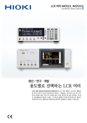
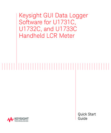
Statistical functionsData storageThe 4287A is equipped with functionsto statistically analyze data. Thesefunctions improve the efficiency ofthe data acquisition required inquality control.The 4287A built-in data storageincludes a 3.5 inch floppy disk driveas well as a hard disk drive. Thesepowerful storage devices permitsave and recall of measurementsetup parameters (instrument state)and measurement data. In addition,measurement setup parametersand data can be transferred betweenthe 4287A and an external computervia the GPIB or LAN interface.The statistical analysis functioncalculates the following statisticalparameters for as many as 240000measurement points. Originalmeasurement results for the statisticalanalysis function can be obtainedvia LAN interface. Examples of normal data(non-failure)Cumulative normal samples, mean,maximum, minimum, standarddeviation, and 3 σ/mean Examples of failure analysisCumulative failure samples,cumulative Rdc failures, cumulativeoverload samples Total number of normal/failuredataInterfacing with an automatedcomponent handlerThe measurement plane can beextended from the front panel ofthe instrument to the measurementstage with the 1 m test cable and thesmall size test head. Note that themeasurement accuracy is specified atthe test head. It is possible to extendthe test cable an additional meterwith a 1 m extension cable. Inaddition, connection to an externalcomputer or an automated componenthandler can be accomplished via theGPIB interface and the opto-isolatedhandler interface. The LAN interfaceenables network communication,and greatly empowers massive datatransfer to a remote computer.PCLANGPIBHandlerHandler I/F3.5 mmSmall test head4287A1 m cable( 2 m max. (Option 4287A-020))Figure 7. Handler system example with the 4287A6
Research and Developmentof Next Generation Devicesand Improving ReliableQuality ControlThe accurate impedance measurementcapability of the 4287A with thevarious kinds of test accessoriesoffers you total measurementsolutions for the areas of researchand development, as well as qualitycontrol.Accurate impedance evaluationup to 3 GHzCharacterization of components atoperating frequencies in excess of2 GHz is becoming common due tothe development and evaluationof RF SMD inductors used inwireless communication equipment.The 4287A employs the RF I-Vmeasurement method of measuringimpedance by measuring the currentflowing through a device undertest (DUT) and the voltage appliedacross the DUT. The 4287A enablesaccurate measurement over animpedance range much wider thanthat of network analyzers (reflectioncoefficient method).Total measurement solutionWhen electronic components areevaluated, the test accessories shouldbe suitable for their shape and sizefor accurate impedance measurements.Agilent offers various kinds of 7-mmtest fixtures, which are compatiblewith the 4287A. You can select theappropriate one for your device'ssize, shape, and application. The16196A, B, C and D SMD test fixtures,developed with a coaxial structure,make RF impedance measurementsto 3 GHz possible. The 16196A, B, Cand D correspond to the chip sizes,1608 (mm)/0603 (inch), 1005 (mm)/0402 (inch), 0603 (mm)/0201 (inch),and 0402 (mm)/01005 (inch)*respectively.The repeatable DUT positioningcapability and reliable contactsenable stable measurement results,and reduce the possibility of operatorinduced error. Evaluation of SMDinductors to 3 GHz, which has beendifficult to implement so far, caneasily be performed with goodrepeatability by using the 4287Awith the 16196A/B/C/D test fixtures.When the 16200B is used with the4287A, a 7 mm test fixture, and anexternal dc bias source, dc biascurrent can be applied to devicessuch as the EMI filter (up to 1 GHz).CapUpper electrodeDUTInsulatorOuter connectorLower electrode7 mm connectorFigure 8. Cross-sectional drawing of 16196A/B/C*EIAJ/EIA chip size codeFigure 9. Total measurement solution example (with 16196A)7
Advanced Features ForPrecise and VersatileAnalysis10090For manual measurements, alow-loss capacitor as a phasecalibration standard, in additionto open/short/load calibration,improves the accuracy of Qmeasurements as shown. Inaddition to calibration, electricallength compensation for a fixturewith open/short compensationfully correct measurement errorcaused by use of a test fixture.These functions realize highabsolute measurement accuracyat the measurement plane, whichin turn empowers accuratemeasurement of working standards.Qx 30080Q Accuracy ( Q x / Q x) [%]Powerful calibration andcompensation functions70605040Qx 10030201001M10M100M1G3GFrequency [Hz]Figure 10. Q accuracy @ 7-mm port (typical)Calibration wizard functionThe 4287A offers you thesophisticated calibration/compensation method, calibrationwizard function. The calibrationwizard function eliminates errorsof troublesome calibration/compensation procedures, andit allows you to easily make the4287A ready to measure accurately.Figure 11. Calibration wizard (fixture connectionafter calibration)Figure 12. Calibration wizard (open compensation)Frequency characteristics byusing list sweep functionIn the area of research anddevelopment, the frequencycharacteristics of the devicecan be required for their circuitdemands. The 4287A’s list sweepfunctions enable impedancemeasurements at a maximum of256 multiple frequency points( 32 points max./table x 8 tablemax.). By using an external PC,spreadsheet software, andLAN interface, the frequencycharacteristics can be plottedin a graph as shown below.8Figure 13. Frequency characteristics plot using spreadsheet software
Ordering Information4287A RF LCR meterFurnished accessories: Test head with 1 m test cableN (m) - SMA (f) AdapterWrench for 3.5/SMA connectorCD-ROM (Operation manual, Programming manualand Sample Program) Power cordNote: A keyboard and a mouse are required for initialsetup of 287A-7204287A-8104287A-8204287A-1A7Add working standard set1Add test fixture extension cable set (1 m)16195B calibration kit2Test fixture stand3.5 mm to 7 mm coaxial adapterAdd keyboardAdd mouseISO 17025 compliant calibrationPaper manual options4287A-ABJ4287A-ABA4287A-0BWJapan-Japanese localizationU.S.-English localizationAdd service manualCabinet options4287A-1CM4287A-1CN4287A-1CPRack flange kitFront handle kitHandle/rack mount kitNote:1. This is used to calibrate the 4287A at the handler DUT contacts. It consists of shorting bars, and 51.0 Ω chip resistors. (SMD size: 1.0 x 0.5 mm, 1.6 x 0.8 mm, 2.0 x 1.2 mm, 3.2 x 1.6 mm)2. The 16195B is used to calibrate the 4287A at the 7 mm calibration plane by using the 3.5-mm to 7-mm adapter. It consists of open, short, load, and low-loss capacitor standards.9
Accessories16197A SMD test fixture16196A/B/C/D SMD test fixture- Frequency range: DC to 3 GHz- Connector: 7-mm- Operating temperature range:55 C to 85 C- Accommodate SMD sizes:3216 (mm)/1210 (inch)3216 (mm)/1206 (inch)2012 (mm)/0805 (inch)1608 (mm)/0603 (inch)1005 (mm)/0402 (inch)- Frequency range: DC to 3 GHz- Connector: 7-mm- Operating temperature range:–55 C to 85 C- Accommodate SMD sizes:- 16196A: 1608 (mm)/0603 (inch)- 16196B: 1005 (mm)/0402 (inch)- 16196C: 0603 (mm)/0201 (inch)- 16196D: 0402 (mm)/01005 (inch)16194A High temperaturecomponent fixture- Operating frequency: DC to 2 GHz- Operating temperature range:–55 C to 200 C- Accommodated SMD size:See Figure 19.Figure 17. 16194A16200B External DC bias adapterFigure 14. 16196A/B/C. 16196D has a differentcap shape.16192A SMD test fixtureFigure 16. 16197A- Operating frequency: 1 MHz to 1 GHz- External DC bias: 5 A max, 40 V(at the BNC connector from theexternal dc bias source)- Operating temperature range:0 C to 55 C- Operating frequency: DC to 2 GHz- Accommodated SMD size:See Figure 19.Figure 18. 16200BFigure 15. 16191A/16192A16192A16197AL 1.0 - 20.0 mmL 1.0 - 3.2 mmLL16194AL 15 mmL 4.5 mmL 2.0 - 15.0 mmLL 8.0 - 21.0 mmHLFigure 19. Accommodated SMD size10W
Ordering InformationAccessories116196A2Parallel electrode SMD test fixtureOption 16196A-710 Add magnifying lens and tweezersOption 16196A-ABA U.S. - English localizationOption 16196A-ABJ Japan - Japanese localization16196B2Parallel electrode SMD test fixtureOption 16196B-710 Add magnifying lens and tweezersOption 16196B-ABA U.S. - English localizationOption 16196B-ABJ Japan - Japanese localizationParallel electrode SMD test fixtureOption 16196C-710 Add magnifying lens and tweezersOption 16196C-ABA U.S. - English localizationOption 16196C-ABJ Japan - Japanese localizationParallel electrode SMD test fixtureOption 16196D-710 Add magnifying lens and tweezersOption 16196D-ABA U.S. - English localizationOption 16196D-ABJ Japan - Japanese localization16196UMaintenance kits for 16196XOption 16196U-010Upper electrode set for16196A/B/C (5 ea)Upper electrode set for 16196D(5 ea)1608 (mm) short plate set (5 ea)1608 (mm) lower electrode set(5 ea)1005 (mm) short plate set (5 ea)1005 (mm) lower electrode set(5 ea)0603 (mm) short plate set (5 ea)0603 (mm) lower electrode set(5 ea)0402(mm) short plate set (5 ea)0402(mm) lower electrode set(5 ea)Option 16196U-200Option 16196U-210Option 16196U-300Option 16196U-310Option 16196U-400Option 16196U-41016192A3Option 16192A-010Option 16192A-71016194A316196D2Option 16196U-100Option 16196U-110Bottom electrode SMD test fixtureAdd 0201 (inch)/0603 (mm) deviceguide setOption 16197A-ABA U.S. - English localizationOption 16197A-ABJ Japan - Japanese localizationOption 16197A-001Option 16192A-70116196C2Option 16196U-02016197A2Option 16194A-010Option 16194A-70116200B16190B4Parallel electrode SMD test fixtureEIA/EIAJ industry sized short barSetShort bars set (1 x 1 x 2.4,1.6 x 2.4 x 2, 3.2 x 2.4 x 2.4,4.5 x 2.4 x 2.4) mmAdd magnifying lens and tweezersHigh temperature component fixtureEIA/EIAJ industry sized shortbar setShort bars set (1 x 1 x 2.4,1.6 x 2.4 x 2, 3.2 x 2.4 x 2.4,4.5 x 2.4 x 2.4) mmExternal DC bias adapterPerformance test kit, 7-mmNote:1. Manual is not furnished as standard.2. Must specify one of language options (ABA or ABJ) for operation manual for shipment with product. For 16196A/B/C/D, magnifying lens and tweezers are not furnished as standard.3. Short bar set is not furnished as standard. Magnifying lens and tweezers are not furnished as standard.4. This kit includes an open, a short, a 50 Ω terminations, and an air line for the performance test to verify the impedance accuracy.11
Web Resourcewww.agilent.com/find/lcrmetersAgilent Email Updateswww.agilent.com/find/emailupdatesGet the latest information on the productsand applications you select.Agilent Directwww.agilent.com/find/agilentdirectQuickly choose and use your testequipment solutions with confidence.Remove all doubtwww.agilent.comOur repair and calibration services will getyour equipment back to you, performinglike new, when promised. You will getfull value out of your Agilent equipmentthroughout its lifetime. Your equipmentwill be serviced by Agilent-trained technicians using the latest factory calibrationprocedures, automated repair diagnosticsand genuine parts. You will always have theutmost confidence in your measurements.For more information on AgilentTechnologies’ products, applicationsor services, please contact your localAgilent office. The complete list isavailable in AmericaUnited States(877) 894-4414305 269 7500(800) 829-4444Agilent offers a wide range of additionalexpert test and measurement services foryour equipment, including initial start-upassistance onsite education and training,as well as design, system integration, andproject management.Asia PacificAustraliaChinaHong 1 800 629 485800 810 0189800 938 6931 800 112 9290120 (421) 345080 769 08001 800 888 8481 800 375 81000800 047 8661 800 226 008For more information on repair andcalibration services, go towww.agilent.com/find/removealldoubtEurope & Middle EastAustria0820 87 44 11Belgium32 (0)2 404 93 40Denmark45 70 13 15 15Finland358 (0)10 855 2100France0825 010 700**0.125 /minuteGermany01805 24 6333****0.14 /minuteIreland1890 924 204Israel972-3-9288-504/544Italy39 02 92 60 8484Netherlands31 (0)20 547 2111Spain34 (91)631 3300Sweden0200-88 22 55Switzerland0800 80 53 53United Kingdom 44 (0)118 9276201Other European Countries:www.agilent.com/find/contactusRevised: March 27, 2008Product specifications and descriptions inthis document subject to changewithout notice. Agilent Technologies, Inc. 2000, 2003,2004, 2005, 2008Printed in USA, April 10, 20085968-5443E
6 GPIB Handler I/F LAN PC Handler 4287A Small test head 3.5 mm 1 m cable ( 2 m max. (Option 4287A-020)) Figure 7. Handler system example with the 4287A