Transcription
CUS
2Canadian Air Handler Installation and Operation Manual
Thank you for purchasing Rinnai’s HydronicAir Handler.Before installing and operating the air handler,be sure to read these instructions completelyand carefully to familiarize yourself with thefeatures and functionality.This manual provides instructions for installingthe air handler and is a supplement to theRinnai Tankless Water Heater or BoilerInstallation and Operations Manual suppliedwith the system.The air handler must satisfy all therequirements in the Tankless Water Heater orBoiler Installation and Operations Manual, aswell as the requirements in this manual. You must read the entire manual toproperly operate the air handler. It is recommended that a trained andqualified professional who has attended aRinnai installation training class completeyour installation. Keep this manual for future reference. It is recommended that a trained andqualified professional who has attended aRinnai installation training class install theair handler, inspect it, and leak test it beforeuse. Improper installation may void thewarranty. The trained and qualified professionalshould have skills such as: Connecting water lines, valves,electricity Knowledge of applicable national,state, and local codes Installing ductwork and other HVACequipment Training in installation of air handlers.Training on Rinnai’s hydronic airhandler is accessible at www.rinnailms.com. Read all instructions in this manual beforeinstalling the hydronic air handler. Thehydronic air handler must be installedaccording to the exact instructions in thismanual. When installation is complete, leave thismanual with the air handler or give themanual directly to the consumer. Proper installation is the responsibility ofthe installer.Dealer Name:Dealer Phone:Purchase Date:Serial #:Located on top of unitCanadian Air Handler Installation and Operation Manual3
This manual contains the following importantsafety symbols. Always read and obey all safetymessages.Safety alert symbol. Alerts you topotential hazards that can kill orhurt you and others. Suitable fire extinguishing equipment shouldbe immediately available in the work areaand be maintained in a state of readiness forinstant use. Do not use this air handler if any part hasbeen under water. Immediately call alicensed professional to inspect the airhandler and replace any part that has beenunder water.Do not use substitute materials. Use onlyparts certified for the air handler.Do not use an extension cord or adapter plugwith this air handler. DANGERIndicates an imminently hazardoussituation which, if not avoided, will resultin personal injury or death. Any alteration to the air handler can bedangerous and will void the warranty. This air handler must be installed indoors. Improper installation, modification, service,maintenance or use of the air handler cancause electrical shock, burns or otherconditions which may cause personal injuryor property damage. It is recommended that a trained andqualified professional who has attended aRinnai installation training class completeyour installation.Read these installation instructions carefullyand adhere to all warning and cautionstatements. Consult local building codes,Occupational Safety and HealthAdministration (OSHA), and NationalElectrical Code (NEC) for specialrequirements.WARNINGIndicates a potentially hazardous situationwhich, if not avoided, could result in personalinjury or death.CAUTION Indicates a potentially hazardous situationwhich, if not avoided, could result in minoror moderate injury. It may also be used toalert against unsafe practices.The following precautions apply to the installerand consumer. Read and follow all instructions inthis section. 4Before any work is undertaken, it isimperative to observe all precautions asstated in this manual.Wear safety glasses and work gloves.WARNINGBefore installing or servicing the air handler,turn off the power to unit. There may be morethan one disconnect switch. Electrical shockcan cause personal injury or death.Canadian Air Handler Installation and Operation Manual
The hydronic air handler is designed to workwith Rinnai tankless water heaters and boilers(models listed below) to deliver a wide varietyof heating capacities for residential and lightcommercial applications.NOTERefer to section “3.7 Specifications” for acomplete list of product specifications.It is the responsibility of the installer to follow allnational codes, standards and local ordinances,in addition to the instructions in this manual. Theinstallation must comply with regulations of thelocal building, heating, plumbing, and othercodes. Where local codes are not applicable, theinstallation must comply with the national codesand all authorities having jurisdiction.The following is a suggested list of codes andstandards for the United States and Canada:General Installation Installation of Air Conditioning andVentilating Systems NFPA 91 (latest edition)The hydronic air handler works with the followingRinnai products: Rinnai Tankless Water Heaters: SENSEI SE Series(RU Condensing Models) CSA B214-01 Installation Code for HydronicHeating SystemsDuct Systems Sheet Metal and Air ConditioningContractors National Association (SMACNA) American Society of Heating, Refrigeration,and Air Conditioning Engineers (ASHRAE)NOTETankless water heaters must have aminimum input rate of 160,000 Btu/hr.RUR condensing model water heatersare not approved for use with this is airhandler. 2001 Fundamentals Handbook Chapter 34or 2000 HVAC Systems and EquipmentHandbook Chapters 9 and 16 US and CANADA: Air ConditioningContractors Association (ACCA) Manual DAcoustical Lining and Fibrous Glass Duct US and CANADA: Current edition ofSMACNA; NFPA 90B as tested by ULStandard 181 for Class I Rigid Air DuctsRinnai Boilers: I-Series (Condensing) Combi ModelsElectrical ConnectionsNOTEIf utilizing a boiler, ensure the output ofthe boiler exceeds the capacity of theair handler in use (the boiler Btu/hrrating must be greater than the airhandler Btu/hr rating). US: National Electrical Code (NEC) ANSI/NFPA 70 (latest edition) CANADA: Canadian Electrical Code CSAC22.1 (latest edition)Plumbing Systems US and CANADA: ICC InternationalPlumbing Code (IPC); Uniform MechanicalCode (UMC); Uniform Plumbing Code(UPC), National Plumbing Code (NPC)Canadian Air Handler Installation and Operation Manual5
When transporting components of the hydronicair handler, follow the guidelines below: Choose the correct hand truck to supportthe weight and size of the systemcomponents. Refer to section “3.7Specifications” for specific weights anddimensions. Use safe lifting and material handlingprinciples to prevent workplace accidents.Example:CAH050CECAH050CEBlower Motor Use proper lifting techniques to load theequipment onto a hand truck.E ECM Motor Position the equipment onto the handtruck so the weight is evenly balanced.AccessoryCirculator Pumpincluded with theair handler (ifapplicable) Use personal protective equipment, suchas gloves and steel-toed boots.Nominal Heating Capacityat 3GPM and 140 FIf storing components of the hydronic airhandler, follow the guidelines below:050 50,000 BTU Store system components in a clean, dryenvironment. Components must be protected fromdirect sunlight. Do not store components outdoors. If transported or stored at temperaturesbelow 32 F (0 C), the components mustbe warmed up to 60 F (15 C) before thestart of assembly.SeriesCAH Series All components must be stored in theoriginal packaging.6Canadian Air Handler Installation and Operation Manual
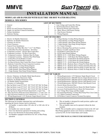
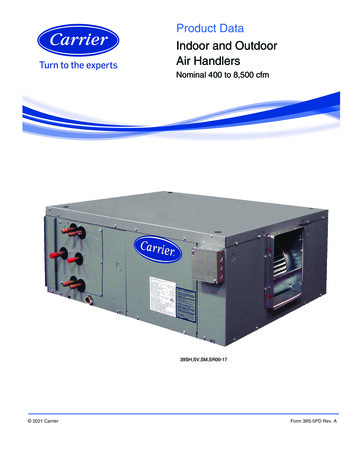
Water InletHot Water From WaterHeater/Boiler into AirHandlerHydronicCoilTOPWater OutletCold Water Returning toWater Heater/BoilerControl Panel120V Terminal24V Thermostat CableKnockout Access Port(available on left or rightside)ECM Blower Motorand Housing120V Power SupplyKnockout Access Port(available on left or rightside)Left or Right Side HVACDuct ReturnAcoustic WoolNOTEBottom HVACDuct ReturnBOTTOMCanadian Air Handler Installation and Operation Manual Reference to the "top" and "bottom"are referring to the location in thisimage and will not change based onorientation of the product. Cover is removed in above image toshow the air handler internalcomponents.7
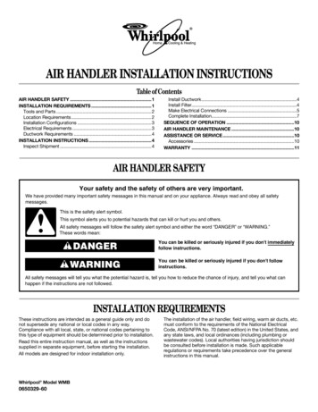
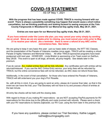
A-Coil and Ductwork(Field-Supplied)Refrigerant Lines (FieldSupplied) to Condensing UnitWater Inlet/Outlet FromWater Heater/Boiler (theyare co-linear and cannotboth be seen on the sideprofile)Air Handler8Canadian Air Handler Installation and Operation Manual
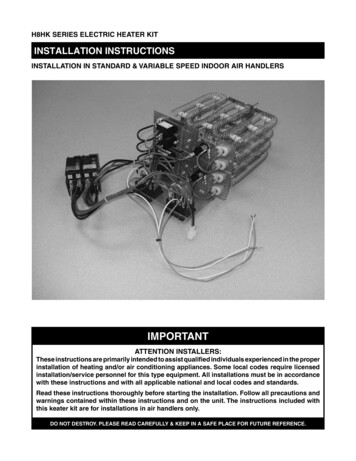
Example Vertical (Upflow withSide Return) ConfigurationSUPPLY(Air Flows Out)SupplyDuctworkRinnai TanklessWater Heateror BoilerThermostatA call for heat from thethermostat activates theair handlerHotColdWater InletRETURNWater OutletFrontPanel(Air Flows In)Hot Water FromWater Heater/Boilerinto Air HandlerCold Water FromAir Handler Returningto Water Heater/BoilerReturnDuctworkAir HandlerIMPORTANTThe above image is for representation purposes only; it is not a complete system.Please follow standard design protocols for installation.Canadian Air Handler Installation and Operation Manual9
CAH050ECAH050CEHydronic Air HandlerHydronic Air Handler(Without Accessory Circulation(With Accessory CirculationPump)Pump)InstallationIndoorSuitable for Potable Water SystemsYesConfigurationsMulti-positionCirculation Pump IncludedNo, AccessoryYes (to be field installed)Product Weight - lb. (kg) (approximate) 100 (45.5), Shipped 120 (54.5) 105 (47.6), Shipped: 125 (56.7)Appliance TypeCabinet: 22 Gauge powder coated steelInner panels: 22 Gauge galvanized steelInsulation: 1/2” inside blower compartment and doorConstruction1600 up to 0.7 in. W.C.1200 up to 1.2 in. W.C.50,000Nominal CFM (Cubic Feet/Minute)Nominal Output Btu/hr at 140 F1Nominal Cooling CapacityUp to 4 tons120 V, 60 Hz, 1 PhMotor: - 9.6A FLA, Pump 3A max15A MOA, 20A MOPECM fully variableCopper Coil, Aluminum Fins3/41/2 in. SweatRated VoltageBlower Motor TypeCoil MaterialBlower Motor Horsepower (HP)Water ConnectionControl BoardP9-11 Energy Efficiency Rating (TPF)Certifications Factory InstalledThermostat connectionsAdjustable time delay for blower activation for heatingPump timer circulates water for one minute every 24 hoursto prevent stagnation of water in the system (default)0.88 with RU160i tankless water heater*CSA 22.2 No 236, UL-1995, NSF 372 (hydronic coil)1 Reference tables in sections 3.7.2 for specific BTU output.* Refer to P9-11 listings for latest information and results.Rinnai products are continually being updated and improved; therefore, specifications are subject tochange without prior notice.10Canadian Air Handler Installation and Operation
Values shown in following tables may vary depending on the static pressure of the duct system.EngineEntering Water50%75%Temperature ( F) (800CFM) (1200 40049,10054,90061,60067,500100%(1600 CFM)41,40044,60057,40064,10072,40081,700With 20ft or less equivalent pipingCoil EnteringHeat Fan Ratio (Air Flow)Flow RateWaterCoil %Temperature(GPM)Drop (PSI)(800CFM) Differential ( F) (1200 CFM) Differential ( F) (1600 CFM) Differential ( F)( 48,00051,2004344505659Flow .344.38Maximum Equivalent PipingDistance (ft)SenseiI-Series200 ft150 ftCanadian Air Handler Installation and Operation Manual200 ft150 ft11
CopperDiameterFitting3/4 in.1 in.90 Degree Elbow20.7545 Degree Elbow0.750.3Straight Through Tee0.40.13531.35Reducer Coupling0.50.18Gate Valve0.250.09Ball Valve2.21.29Swing Check Valve31.35Multiplier Per Linear Foot of Pipe10.3Fitting3/4 in.1 in.90 Degree Elbow19.446.92.70.78Side Port Tee28.087.62Reducer Coupling4.681.62Ball Valve5.942.58PEX x NPT4.862.28Multiplier Per Linear Foot of Pipe1.80.63/4 in.1 in.90 Degree Elbow2.2145 Degree Elbow1.210.56Straight Through Tee1.540.68Side Port Tee5.52.4Male/Female Adapter1.650.8Multiplier Per Linear Foot of Pipe1.10.4Side Port TeeNOTE All values havebeen normalized to3/4 in. copper pipeas a baseline. It is notrecommended touse ½ in. piping asthe pressure drop isconsiderably largerthan ¾ in. piping.PEXStraight Through TeeCPVCFitting 50 ft. of 3/4 in. CPVC pipe Four (4) 90 degree elbows Two (2) straight through teesTotalEquivalentLength 50 x 1.1 (Total linear foot equivalency) 4 x 2.2 (Total for 90 degree elbows) 2 x 1.54 (Total for tees)Approximately 67 Equivalent Feet of Piping12Canadian Air Handler Installation and Operation
Measurements: in. (mm)18.5 (470)14.38(365)17 (432)39.25(997)20.5 (521)Canadian Air Handler Installation and Operation Manual21.38 (543)13
Domestic Priority SwitchPart #Normally Closed (NC) switch that connects to the PC Board in theRinnai tankless water heater or boiler.Allows the tankless water heater or boiler to give priority to domestichot water by shutting off the air handler when necessary. When usedwith a hydronic air handler, the switch gives priority to domestic hotwater. When domestic hot water demand exceeds a certain point, theair handler will turn off to ensure the demand is met.REU-OPU3Product images are for illustrative purposes only.14Canadian Air Handler Installation and Operation
Carefully unpack the air handler. If the unit isdamaged, contact your local dealer/distributor. Donot attempt to use the air handler if it appearsdamaged.The blower section is factory assembled and allcomponents are performance tested.The air handler consists of a blower assemblyand controls in an insulated, galvanized steelfactory finished enclosure. Knockouts areprovided for thermostat electrical wiring entrance.Inspect the following: Check the air handler rating plate to confirmspecifications are as ordered. Upon receipt of air handler, thoroughlyinspect the system for possible shippingdamage. If the carton appears damaged,closely examine the air handler inside thecarton. If the air handler appears to be damaged or istorn loose from its anchorage, the air handlermust be immediately examined by thereceiving party before removal. If damage isfound, the receiving party must sign thedriver’s delivery receipt noting all damage(i.e. carton damage and/or product damage),as well as contact the last carrierimmediately, preferably in writing, requestinginspection by the carrier’s agent. To prevent loss or damage, leave all parts inoriginal packages until installation.When choosing an installation location, youmust ensure proper clearances will be met; theinstallation environment; water quality; and theneed for freeze protection.This section provides information on theimportance of water quality to the air handler. Theinformation is intended to serve as generalguidelines only and is not a complete list of waterquality guidelines.Consideration of care for the air handler shouldinclude evaluation of water quality. Gather the required tools and parts beforestarting installation. Read and follow theinstructions provided with any tools listed below. 1/4 in. nut driver Level Screwdriver Adjustable wrench Tape Measure Hammer AHRI Approved Duct Sealant UL listed wire nutsCanadian Air Handler Installation and Operation ManualThe water must be potable, free of corrosivechemicals, sand, dirt, or other contaminants.It is up to the installer to ensure the waterdoes not contain corrosive chemicals orelements that can affect or damage the boileror tankless water heater.Water that contains chemicals exceeding thelevels below can damage the boiler ortankless water heater.ContaminantTotal HardnessAluminum *Chlorides *Copper *Dissolved Carbon Dioxide(CO2)Iron *Manganese *pH *TDS (Total DissolvedSolids) *Zinc *Maximum LevelUp to 200 mg/LUp to 0.2 mg/LUp to 250 mg/LUp to 1.0 mg/LUp to 15.0 mg/LUp to 0.3 mg/LUp to 0.05 mg/L6.5 to 8.5Up to 500 mg/LUp to 5 mg/L* Source: Part 143 National SecondaryDrinking Water Regulations15
Unsuitable heating system water can causethe formation of scale or sludge, whichaffects system efficiency. It can also causecorrosion and reduce life of the heatexchanger. Clearances tocombustiblematerial is 0 in. toplenum and duct forfirst 36 in. (914 mm)and throughout theremaining ductworksystem.Never use water that has been treated by areverse osmosis, deionized, or distilledwater to soften the water to fill the heatingsystem. IMPORTANTReplacement of components due to waterquality damage is not covered by the warranty.Non-Ducted Return Closet Installation Clearances to combustible material is 0 in.from unit casing, and 0 in. to plenum andduct for first 36 in. (914 mm) and throughoutthe remaining ductwork system. Clearance for servicing is 24 in. (610 mm) infront of air handler.TOP0 in. Louvers or return air grilles are field-supplied.Local codes may limit application of systemswithout a ducted return to single-storybuildings. For a unit installed in a closet with a louveredreturn opening, the minimum open area forthe louvers are:Air Handler Models CAH050E CAH050CEFRONT0 in.SERVICING24 in.(610 mm)SIDE0 in.BACK0 in.BOTTOM0 in.Minimum Opening Area360 square inches(0.23 square meters) If the free area is not known, assume a 25%free area for wood or a 75% free area for metallouvers or grilles. Using the louver dimensionsand the 25% or 75% assumption, determine ifthe louver open area meets the minimum openarea listed above. If the return air plenum is used, the return airgrille should be immediately in front of theopening in the plenum to allow for the free flowof return air. When not installed in front of the opening, theremust be adequate clearance around the airhandler to allow for the free flow of return air.Images are not to scale and are for illustrationpurposes only. Images do not show a completesystem with plenums, duct pipes, etc.16Canadian Air Handler Installation and Operation
This air handler is certified for installation inresidential and light commercial applicationsand approved for the following configurations: Vertical: Upflow with bottom or side (left orright side) return Vertical: Downflow with bottom or side (leftor right side) return Horizontal (Upflow with bottom return) All models are designed for indoor installationonly. These instructions are intended as a generalguide only and do not supersede national orlocal codes. Compliance with all local, state, ornational codes pertaining to this type ofequipment should be determined prior toinstallation. Read this entire manual, as well as theinstructions supplied in separate equipment,before starting installation. It is recommended that a trained and qualifiedprofessional who has attended a Rinnaiinstallation training class complete yourinstallation. Installation of the air handler, field wiring, warmair ducts, etc. must conform to the requirementsof the Canadian Electrical Code CSA 22.1,National Electrical Code, ANSI/NFPA No. 70(latest edition) in the United States, and anystate laws, and local ordinances (includingplumbing or wastewater codes). Localauthorities having jurisdiction should beconsulted before installation begins. Suchapplicable regulations or requirements takeprecedence over the general instructions in thismanual. Install the conditioned air plenum, ducts and airfilters (not provided) in accordance with NFPA90B Standard for the Installation of Warm AirHeating and Air-Conditioning Systems (latestedition). The blower section is provided withflanges for the connection of the plenum andducts. Air filters must be listed as Class 2furnace air filters. The blower section is shippedfrom the factory completely assembled. For ease in installation, it is best to make anynecessary evaporator coil configurationchanges before connecting the air handler tothe evaporator coil. Do not remove the cabinet knockouts until ithas been determined which knockouts needto be removed for the installation. Select the final installation position that bestsuits the site conditions. Consider requiredclearances, space, and routing requirementsfor refrigerant line, condensate disposal,filters, ductwork, wiring, and accessibility forservice. Refer to the rating plate for specificinformation. When the unit is installed in a humid spaceand used in cooling applications, excessivesweating may occur on outside of unit. Toprevent excessive sweating wrap unit with1 in. (25 mm) fiberglass insulation. Allopenings should be sealed to prevent airleakage that could cause condensate to forminside the cabinet. Electrical wires should be sealed on theinside where they exit the conduit opening.Sealant is required to prevent air leakage andcondensate from forming inside the blower,control box, and on the electrical controls. Glycol is permitted in installations with theI-Series boiler up to 50% concentration. Referto the I-Series Condensing Boiler Installationand Operation Manual for approved glycolmanufacturers. The air handler and its complementingcooling coil must be installed in such a wayas to allow free access to the air handler/control compartment.Canadian Air Handler Installation and Operation ManualIMPORTANTThe Clean Air Act of 1990 bans theintentional venting of refrigerant (CFC’s andHFC’s) as of July 1, 1992. Approvedmethods of reclaiming must be followed.Fines and/or incarceration may be levied fornon-compliance.WARNING Do not install this air handler if it isdamaged. Do not install this air handler if any partor all of the unit has been under water.Explosion Hazard: Keep flammable materials and vapors,such as gasoline, away from this unit. Failure to follow these instructions canresult in death, explosion or fire.17
Install ductwork in accordance with NFPA90B and any local codes. Install the conditioned air plenum, ductsand air filters (not provided) in accordancewith NFPA 90B Standard for theinstallation of Warm Air Heating and AirConditioning Systems (latest edition). Isolation connectors (if utilized) must benonflammable. A return air duct system is recommended.If the unit is installed in a confined space orcloset, a return connection must be run, fullsize, to a location outside the closet. The air handler is provided with flanges forthe connection of the plenum and ducts. Air filters must be listed as Class 2 furnaceair filters. Supply and return ductwork must beadequately sized to meet the system’s airrequirements and static pressurecapabilities. Ductwork should be insulatedwith a minimum of 1 in. (25 mm) thickinsulation with a vapor barrier inconditioned areas or 2 in. (51 mm)minimum in unconditioned areas. Supply plenum should be the same size asthe flanged opening provided around theblower outlet and should extend ideally atleast 3 ft. (1 m) from the air handler beforeturning or branching off plenum into ductruns. The plenum forms an extension ofthe blower housing and minimizes airexpansion losses from the blower.18WARNINGBefore installing or servicing the air handler,turn off power to unit. There may be morethan one disconnect switch. Electrical shockcan cause personal injury or death. All wiring must conform to local and nationalelectrical codes. Improper wiring orinstallation may damage thermostat. Air Conditioner Model: The Standard ModelA/C thermostat may be wired with or withoutconnecting a common wire between theindoor equipment and the thermostat.However, it is recommended to use acommon wire whenever possible to preventpower stealing by the thermostat. Heat Pump Model: The standard modelheat pump thermostat is not "powerstealing" and must have both ‘R’ and ‘C’wires connected to operate properly. Thethermostat should have an indicator forwhen auxiliary heat is in use. The thermostat should NOT be mounted: Close to a window, on an outside wall,or next to a door leading to the outside Exposed to direct light and heat from alamp, sun, fireplace, or other heatradiating objects which may cause afalse reading Close to or in direct airflow from supplyregisters and return-air grilles In areas with poor air circulation, suchas behind a door or in an alcoveCanadian Air Handler Installation and Operation
WARNING Use copper conductors only. All field wiring must be done in accordancewith National Electrical Code, applicablerequirements of UL and local codes, whereapplicable. Electrical wiring, disconnect means andover-current protection are to be supplied bythe installer. Refer to the air handler ratingplate for maximum over-current protection,minimum circuit ampacity, as well asoperating voltage. The power supply must be sized andprotected according to the specificationssupplied on the product. This air handler is factory-configured for 120Volts, single phase, 60 Hz. Prior to making any electrical connections,ensure that supply voltage, frequency, andphase are as specified on unit rating plate. Check to ensure that the existing electricalservice is adequate to handle the additionalload imposed by the Hydronic Furnace.Refer to unit wiring diagram for properelectrical connections. All electrical connections MUST comply withNEC or CEC and any other local codes orordinances having jurisdiction. USECOPPER WIRE ONLY. Provide separatebranch electric circuit with field supplieddisconnect switch. Location of disconnect switch to be in clearsite, accessible and in close proximity to theunit. Correct polarity MUST be maintained for120 V wiring. If polarity is incorrect unit willNOT operate.Electrical Shock: Disconnect power before servicing. Replace all parts and panels beforeoperating. Electrically ground the air handler. Connect ground wire to the green groundwire in the air handler electrical panel. Failure to do so can result in death orelectrical shock. Before installing or servicing the airhandler, turn off power to unit. There maybe more than one disconnect switch. If a disconnect switch is to be mounted onthe unit, select a location where a drill orfastener will not contact electrical orhydronic components. Electrical shock can cause personal injuryor death.WARNINGExplosion Hazard: Keep flammable materials and vapors,such as gasoline, away from this unit. Failure to follow these instructions canresult in death, explosion or fire.Line-Voltage Connections: U.S. Installations: Make all electricalconnections in accordance with NationalElectrical Code (NEC) ANSI/NFPA 70 and alllocal codes or ordinances having jurisdiction. Canadian Installations: Make all electricalconnections in accordance with CanadianElectrical Code CSA C22.1 and all authoritieshaving jurisdiction.Check all factory wiring per unit wiringdiagram and inspect factory wiringconnections to be sure none were loosened intransit. Canadian Air Handler Installation and Operation Manual19
Pipe Sizing ConsiderationsWARNINGSolder joints on domestic water lines must bemade with NO-LEAD SOLDER.IMPORTANTUse only approved piping and fitting materials. Ifused in an open loop system with domestic hotwater, potable, lead-free piping must be used.Thermal Expansion of PipingIn all hydronic systems, piping undergoestemperature swings as the system operates.This causes changes in the length of the pipingdue to thermal expansion.If the piping is rigidly mounted, this expansioncan cause annoying popping or squeakingsounds and in extreme cases, the piping caneven buckle.To counter expansion movement, design pipingcircuits with sufficient elbows, tees or expansionloops (only used in large systems) or pipingsupports that allow the tubing to expand andcontract freely.Another alternative is to install an expansioncompensator fitting capable of absorbing themovement.Hydraulic Resistance of Fittings, Valves, andOther DevicesBefore the total hydraulic resistance of a pipingcircuit can be found, the individual hydraulicresistances of all fittings, valves, or other suchcomponents must be determined. One approachis to consider each fitting, valve, or other deviceas an equivalent length of copper tube of thesame pipe size.When selecting a pipe size for a given flow rate,the resulting average flow velocity should bebetween 2 ft. (0.61 m) and 4 ft. (1.22 m) persecond.At water flow velocities of approximately 2 ft.(0.61 m) per second, flowing water will carry airbubbles along a vertical pipe. Average flowvelocities of 2 ft. (0.61 m) per second or highercan draw along air bubbles in a downward flow.At the above stated velocities air bubbles shallbe routed to an air separator where they can becollected and discharged from the system.Average flow velocities higher than 4 ft. (1.22 m)per second could cause flow noise andpremature wear of piping and fittings and shouldbe avoided.Expansion TanksAll liquids used in hydronic heating systemsexpand when heated. For all practical purposes,liquids are incompressible. Any containercompletely filled with a liquid and sealed fromthe atmosphere will experience a rapid increasein pressure as the liquid is heated. To preventthis from occurring, all hydronic systems MUSTbe equipped with an expansion tank. See thefollowing sections for the expansion tankplumbing location: 5.9.1 Rinnai Tankless Water Heater andAir Handler Piping Diagram 5.9.2 Domestic Hot Water RecirculationPiping Diagram 5.9.3 Rinnai I-Series Boiler and AirHandler Piping Diagram 5.9.4 I-Series Boiler with HydraulicSeparation and Air Handler PipingDiagramBy using the equivalent length of piping for allcomponents in the circuit, the circuit can betreated as if it were a single piece of pipe havinga length equal to the sum of the actual pipelength, the total equivalent lengths of all fittings,valves, or other devices.20Canadian Air Handler Installation and Operation
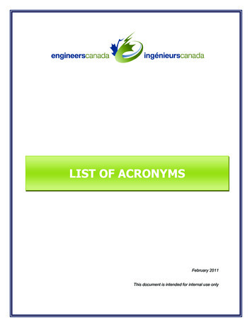
IMPORTANTVertical (downflow with bottom, back, orside return)Read section “4. Installation Preparation”before starting installation steps.RETURN
Rinnai installation training class install the air handler, inspect it, and leak test it before use. Improper installation may void the warranty. The trained and qualified professional should have skills such as: Connecting water lines, valves, electricity Knowledge of applicable national, state, and local codes