Transcription
H8HK Series Electric Heater KitInstallation InstructionsInstallation in Standard & Variable Speed Indoor Air HandlersIMPORTANTATTENTION INSTALLERS:These instructions are primarily intended to assist qualified individuals experienced in the properinstallation of heating and/or air conditioning appliances. Some local codes require licensedinstallation/service personnel for this type equipment. All installations must be in accordancewith these instructions and with all applicable national and local codes and standards.Read these instructions thoroughly before starting the installation. Follow all precautions andwarnings contained within these instructions and on the unit. The instructions included withthis keater kit are for installations in air handlers only.DO NOT DESTROY. PLEASE READ CAREFULLY & KEEP IN A SAFE PLACE FOR FUTURE REFERENCE.
TABLE OF CONTENTSIMPORTANT SAFETY INFORMATION. 2General Information. 2About the heater kit. 2Clearances to Combustibles. 3Standard Air Handlers. 3Variable Speed Air Handlers. 3Electrical Supply. 3Power Wiring. 3Element Installation. 3Electric Heater Kits with Circuit Breakers. 35, 8, & 10 kw Electric Heater Kits. 415, 20, 24, & 29 kw Electric Heater Kits. 43-Phase 9 & 15 kw electric heater kits. 4Line Cover. 4Electric Heater Kits without Circuit Breakers. 4Staged Heat. 4MOTOR SPEED SELECTION. 4Standard Air Handlers. 4Standard 3 Speed Motors. 4Standard C-Cabinets. 4Variable Speed Air Handlers. 4Figures & Tables. 5Figure 1. Heater Kit Identification Code. 5Figure 2. Sample Installation. 5Figure 3. Installation of Circuit Breakers. 5Figure 5. Line Cover Installed. 5Figure 4. Line Cover. 5Figure 6. Circuit Breaker Bracket withTerminal Block Installed. 5Table 1. Blower Heating Speed. 6Table 2. HMG Cabinet Sizes. 6Table 3. Electrical Ratings. 6Figure 7. H8HK Heater Kit Installation. 6Wiring Diagrams. 7Figure 8. Single Phase, 3kW & 5 kw W.D. 7Figure 9. Single Phase, 8kw & 10 kw W.D. 8Figure 10. Single Phase, 15 kw W.D. 9Figure 11. Single Phase, 20 kw WD. 10Figure 12. Single Phase, 25 kw WD. 11Figure 13. Single Phase, 30 kw W.D. 12Figure 14. 3-Phase, 9kw & 15kw W.D. 13Figure 15. 3-Phase, 460V W.D. 142IMPORTANT SAFETY INFORMATIONINSTALLER: Please read all instructions before servicingthis equipment. Pay attention to all safety warnings andany other special notes highlighted in the manual. Safetymarkings are used frequently throughout this manual todesignate a degree or level of seriousness and should notbe ignored. WARNING indicates a potentially hazardoussituation that if not avoided, could result in personal injury ordeath. CAUTION indicates a potentially hazardous situationthat if not avoided, may result in minor or moderate injuryor property damage.WARNING:ELECTRICAL SHOCK, FIRE OREXPLOSION HAZARDFailure to follow safety warnings exactly couldresult in serious injury or property damage.Improper servicing could result in dangerousoperation, serious injury, death or propertydamage. Before servicing, disconnect all electricalpower to the unit. When servicing controls, label all wires priorto disconnecting. Reconnect wires correctly. Verify proper operation after servicing.General InformationAbout the heater kitH8HK Series electric heater kit is approved for field installationin B5, B6, MB7, HMG, HMB, & HCG, air handlers. All sizesare available with factory-provided circuit-breakers for shortcircuit protection and to provide a disconnecting means. Alsoavailable are 5, 8, and 10 kw electric heater kits without circuitbreakers. Refer to the National Electric Code (ANSI/NFPA70) and applicable local codes for over-current protectionand disconnect requirements.NOTES: The 20, 24, and 29 kw electric heater kits are Not approvedfor installation in A-cabinet air handlers. The 24 & 29 Kwkits are for B6, MB7, HMG, HMB, & HCG C-cabinet airhandlers. For all heater kit applications, use Table 1, Table2, Table 3 (page 6), and Figure 1 (page 5). These instructions are written assuming the air handler isin the upflow position (outlet facing up). For horizontal anddownflow applications, it is recommended that the electricheater kit be installed prior to installation of the air handler. Use caution when handling or installing this component.Personal injury can occur from sharp metal edges presentin all sheet metal constructed equipment. 460V heater kits are only approved for use in the 460VMB7 (C-cabinet) air handler.
Clearances to CombustiblesStandard Air HandlersAll installations of H8HK electric heater kits in standard airhandlers are approved for zero-clearance to combustibleswhen the minimum electric heat airlfow is set as directed inthese instructions.Variable Speed Air HandlersAll installations of H8HK electric heater kits in variable speedair handlers are approved for zero-clearance to combustibleswhen the minimum electric heat airflow is set as directed inthese instructions.Electrical Supply All electrical connections must be in compliance with allapplicable local codes with the current revision of theNational Electric Code (ANSI/NFPA 70). For Canadianinstallations the electrical connections and grounding shallcomply with the current Canadian Electrical Code (CSAC22.1 and/or local codes). If the air handler was previously installed without electricheat, the existing supply wiring may not be sufficient tocarry the increased load. If installing electric heat in theair handler, the supply wiring can be aluminum or copper.The supplied circuit breakers and terminal blocks areapproved for either wire type. Make sure to follow all ofthe rating information on the circuit breaker or terminalblock and that the supply wiring is sized according to thecurrent NEC codes and any other state or local codes.See the rating label or Table 3 (page 6) for minimumcircuit ampacities and maximum overcurrent protection. All heater kits are supplied from the factory configured foruse with one or more supply circuits. 5 & 10 kw heaterkits 10 are configured for use with a single supply circuit(Circuit A). 15 & 20 kW heater kits are configured for usewith 2 circuits (Circuit A & Circuit B). 24 & 29 kW heaterkits are configured for use with 3 circuits (Circuit A, CircuitB, & Circuit C). See Table 3 for additional information.NOTE: If a single supply is desired, accessory kit #913874is required to convert to single circuit connection.Power WiringAll wiring must comply with the current revision of the NationalElectric Code and must be sized for the minimum ampacitiesas listed on the unit data label or in Table 3. Refer to Figure8 (page 7), Figure 9 (page 8), Figure 10 (page 9),Figure 11 (page 10), Figure 12 (page 11), Figure 13(page 12), & Figure 14 (page 13) for proper connections.If a single circuit adaptor kit is used it may need to be reconfigured for some applications. Remove the single circuitadaptor kit cover and verify that the lugs are configuredcorrectly for the application. If the lugs are not configuredfor the application, reference the instructions included withthe kit and modify the configuration. Install the single circuitadaptor kit (if used) in the line side (“on” end) of the circuitbreakers. Tighten the lugs securely (45 in-lbs recommended).Connect the supply wiring to the circuit breaker(s), singlecircuit adaptor kit, or terminal block. Tighten the lugs securely.When using multiple supply circuits verify that the supplysized for circuit “A” is connected to the circuit breaker thatis connected to the top element assembly.Install metal circuit breaker line cover on the left side of thecircuit breaker to cover the supply wires.Element Installation1. Set the thermostat to the lowest temperature setting.2. Turn off all electrical power to the air handler.3. Remove the upper access door from the air handler.4. Remove the screws securing the upper element close-offplate from the back of the air handler control box.5. Remove the element close-off plate and set the screwsaside. Do not discard the screws. NOTE: For 2-tieredelectric heater kits, remove two close-off plates. For3-tiered electric heater kits remove all 3 close-off plates.The close off plates should be removed from the bottomup in ascending order.6. Insert the element assembly into the opening in theair handler control box being careful not to damagethe element wire or the ceramic element supports.NOTE: Heating element alignment rods will slide intoalignment holes in the back of the air handler element box.7. Secure the element assembly to the back of the air handlercontrol box with the screws removed in step 4. For 15, 20, 24, or 29 kw Heater Kits the AC relay bracketalso needs to be installed.a.) Place the AC relay bracket below the bottom elementplate so the back edge is behind the element plate.b.) Line up the slot hole on the bracket with the half holeon the element plate. See Figure 7 (page 6).8. Single Stage Board: Connect the W wires from the controlboard (white), AC relay (white) and the W wire from thethermostat with one of the supplied wire nuts. Connectthe C wires from the board (grey), AC relay (grey) and Cwire (if supplied) from the thermostat with one wire nut.Two-Stage Board: Place the W1 wire from the thermostatand the white wire from the AC relay under the W1 screwterminal on the board. Place the C wire from the thermostat(if present) and the grey wire from the AC relay underneaththe C terminal on the control board.9. Connect the 2-Pin Power plug from the element assemblyinto the unit's 2-Pin power plug. Connect the 7-Pin Harnessfrom the element assembly to the unit's circuit board.NOTE: A wiring diagram and a rating label are suppliedwith the electric heater kit. Affix the wiring diagram to theblower housing. When installing the electric heater kit into a standard airhandler, affix the supplied rating label over the electricaldata section of the air handler unit data label located onthe lower access door. When installing the electric heater kit into a variable speedair handler, the rating label supplied with the kit will NOTbe used. Check the appropriate block on the air handlerratings label located on the lower access door.8. Install the circuit breaker bracket inside of the air handler.Position the tab on the bottom of the bracket into the slotof the control panel box. See Figure 2 (page 5) forproper location of bracket.9. Slide the bracket forward and align the screw holes withthe holes in the bottom of the control panel box. Securethe bracket to the air handler with the supplied screws.Electric Heater Kits with Circuit BreakersNOTE 1: Circuit breakers supplied with the H8HK electricheater kit are for short-circuit protection of the internal wiringand to serve as a unit disconnect. They DO NOT provideover-current protection of the supply wiring. Over-currentprotection of the supply wiring must be provided at the3
distribution panel and sized as shown in Table 3 (page 6)or the unit data label, and in accordance with the NEC andall applicable local codes.NOTE 2: In some cases, the over-current protection specifiedin Table 3 (or the unit data label) is less than the 60 amp ratingof the circuit breakers used in the H8HK electric heater kit.This difference may occur if the function of the over-currentprotection required at the distribution panel (field supplied)and the function of the circuit breakers in the H8HK electricheater kit are different.5, 8, & 10 kw Electric Heater Kits1. Snap the circuit breaker onto the circuit breaker bracket.The circuit breaker must be positioned with the 1/4" tabterminals to the right as shown in Figure 3 (page 5).2. Remove the lower circuit breaker knockout from the airhandler upper access door.15, 20, 24, & 29 kw Electric Heater KitsNOTE 1: The heavy red and black supply leads are bundledby circuit with wire ties at the factory. The bundle comingfrom the top element tier is circuit “A”.NOTE 2: The element assembly is right-side-up when thelimits are on the right side). The bundle coming from thesecond element tier is circuit “B”. The bundle coming fromthe bottom element tier is circuit "C".1. Snap the circuit breaker onto the circuit breaker bracket.The circuit breaker must be positioned with the 1/4" tabterminals to the right as shown in Figure 3 (page 5)2. Remove all necessary circuit breaker knockouts in the airhandler upper access door.3-Phase 9 & 15 kw electric heater kits1. Snap the 3-pole circuit breaker onto the circuit breakerbracket. The circuit breaker must be positioned with the1/4" tab terminals to the right as shown in Figure 3 (page5).2. Remove the bottom two circuit breaker knockouts in theair handler upper access door.Line CoverHeater Kits with circuit breakers are supplied with a linecover shown in Figure 4 (page 5). The line cover isrequired by code in order to protect installers from the line/supply wiring. The line cover should be installed as shownin Figure 5 (page 5).Electric Heater Kits without Circuit Breakers1. Attach the supplied power terminal block to the circuitbreaker bracket with the supplied screws as shown inFigure 6 (page 5).2. Using the 1/4" terminals, connect the red supply wire(s)from the element assembly to one pole of the terminalblock and connect the black wires to the other pole.Staged HeatAll Single-phase heater kits are internally staged using B5,B6, HMG and HMB air handler circuit board logic. B5 airhandlers may stage the heater kit with a slow or fast timedoption. B6 single stage air handlers will not stage the heaterkit. B6 two-stage air handlers may stage the heat Kw turnedon with either a low or high heat call. All 3-phase heater kitsare not equipped for internal staging. Refer to the installationinstructions supplied with the air handler for additional staginginformation.4MOTOR SPEED SELECTIONStandard Air HandlersThe blower speed is preset at the factory for operation atthe same speed for heating and cooling, by using the blowermotor jumpering terminal on the blower motor and connectingit to the desired speed with both the red and black wiresconnected to the jumpering terminal. For optimum systemperformance and comfort, it may be necessary to changethe factory set speed. To change the blower speed:WARNING:To avoid the risk of electric shock, personalinjury, or death, disconnect all electrical powerto the unit before performing any maintenanceor service. The unit may have more than oneelectrical power supply.1. Disconnect all electrical power to the unit and remove theupper door.2. Remove the black and red wires from the blower motorjumping terminal.3. Connect the heating speed wire (red) and the coolingspeed wire (black) to the desired blower speed marked onthe terminal block of the blower motor. If needed, re-usethe motor jumping terminal.IMPORTANT NOTEAfter changing the blower speed setting, make sure tobundle and insulate any unused blower motor leadsso that they will not make contact with the air handlercabinet or non-insulated live parts.Standard 3 Speed MotorsTerminal 4 Hi speedTerminal 5 Med speedTerminal 6 Low speedStandard C-CabinetsTerminal M1 Low speedTerminal M2 Medium Low speedTerminal M3 Medium speedTerminal M4 Medium Hi speedTerminal M5 Hi speed.High speed operation may be required when using a 20, 24,or 29 kw electric heater kit in a downflow application. Alsosee Clearances to Combustibles (page 3).4. Replace the upper door and secure it to the unit.5. Restore power to the unit.Variable Speed Air HandlersThe minimum electric heat airflow is selected by settingswitches on the air handler circuit board. Selecting theminimum electric heat airflow sets the minimum air flow thatwill be produced whenever electric heater kits are energized.When the electric heater kits are energized along with a heatpump, the airflow may be higher depending on the basiccooling/heat-pump airflow setting. Reference the installationinstructions supplied with the air handler for additional airflowinformation.
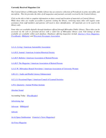
Figures & TablesH8HKProduct Type:H-HeaterGeneration:6 - Sixth Series020-H21StageSequencerNo. of BreakersPrimary Capacity:005 - 5Kw015 - 15Kw008 - 8Kw020 - 20Kw009 - 9Kw024 / 025 - 25Kw010 - 10Kw 029 / 030 - 30KwProduct Identifier:HK - Heater KitElectric Code:H 240 - 1 - 60Q 208 / 240 - 3 - 60S 480 - 3 - 60Figure 1. Heater Kit Identification Code7 - Pin Connector2 - Pin ConnectorCircuit BreakerBracketFigure 2. Sample Installation(shown with access door removed)Figure 3. Installation of Circuit BreakersFigure 4. Line CoverFigure 5. Line Cover InstalledFigure 6. Circuit Breaker Bracket withTerminal Block Installed5
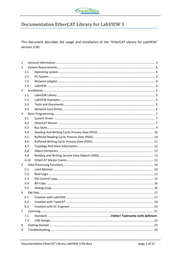
09Q015Q009S015SMinimum Required BlowerHeating XXXLOWLOWLOWLOWLOWMEDMEDLOWLOW1150 CFM1400 CFMLOWLOWLOWLOWLOWMEDMEDLOWLOW1150 CFM1400 CFMLOWLOWLOWMEDHIGHHIGHN/ALOWMED1150 CFM1400 CFMXX(1) Only on *30 (2.5 Ton) model air handlersTable 1. Blower Heating SpeedModelCabinet G048H(M,C)G060AABBCCLine up the slot hole on thebracket with the half hole onthe element plateFigure 7. H8HK Heater Kit InstallationTable 2. HMG Cabinet SizesStandard Air Handler(A & B Size)Circuit BCircuit CSingleCircuitCircuit ACircuit BCircuit CSingleCircuitCircuit ACircuit BCircuit .814.418.021.69.014.46.810.8-Circuit 901251501754050608010012515040604050Table 3. Electrical Ratings6Max. Over-CurrentCircuit S-XX015S-XXMinimum CircuitAmpacityCircuit CKwMax. Over-CurrentCircuit AmpacityCircuit BVoltageMinimum CircuitAmpacityVariable Speed & Standard Air Handler(C Size)Circuit AModelNumberH8HK-Place the AC relaybracket behind theelement plate.
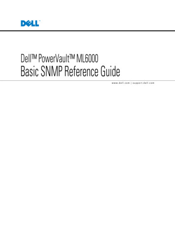
LEGEND:FIELD WIRINGLOW VOLTAGEHIGH VOLTAGE7-PIN PLUG12ORANGEGREYDC RELAYNOTES:1. If any of the original wire supplied with this unitmust be replaced, it must be replaced with wiringmaterial of the same gauge size and temperaturerating.2. The installation of this heater kit may require a changein the blower speed tap connection. See InstallationInstructions for details.3. Use copper conductors with a minimum temperaturerating of 60 C for supply connections.WIRING DIAGRAMBLACKBLACKBLACKREDREDLIMITREDAC RELAYWHITEGREY05/15711433A(Replaces 7114330)TO CONTROL BOARDTO CONTROL BOARD3 kW, 5 kW, 1-Phase Electric Heater KitREDCIRCUITBREAKER(Circuit breakermodels only)TERMINAL
air handler, the rating label supplied with the kit will NoT be used. Check the appropriate block on the air handler ratings label located on the lower access door. 8. Install the circuit breaker bracket inside of the air handler. Positio