Transcription
Product DataIndoor and OutdoorAir HandlersNominal 400 to 8,500 cfmA39-460139SH,SV,SM,SR00-17 2021 CarrierForm 39S-5PD Rev. A
Features/BenefitsDelivering the air handlercomponents for manystringent specificationrequirements, the 39S Seriesair handlers are compact andcombine versatility witheconomical, dependableperformance.The 39S Series air handlersoffer: Horizontal and vertical draw-thruarrangements for heating, cooling,ventilation, and VAV (variable airvolume) applications Small footprint, which assures rigging ease and reduced spacerequirementsDependable performanceGalvanized steel panels reducethe likelihood of corrosion to helpmaintain structural integrity undermost operating conditions. Doublewalled hinged access doors on outdoorunits also enhance structural stabilityand provide fast, easy access.Optional stainless steel drain pancontrols condensate.Internally mounted motors anddrives are installed and aligned at thefactory. Because they are containedin a cooled, filtered, dehumidifiedairstream, motor bearings and beltshave less wear and require lessAHRI certificationThe Air-Conditioning, Heating and Refrigeration Institute (AHRI) is a voluntary, nonprofit organization comprised of the manufacturers of air conditioning, refrigeration, and heatingproducts. More than 90% of the airconditioning and refrigeration machinery and components manufactured inthe United States is produced by members of AHRI.2servicing than motors mounted externally. Internal mounting also reducesinstallation time, shipping damage, andvandalism.Precision-balanced fan wheelslimit vibration and reduce abnormalstress on bearings and othercomponents.Motor start/stop station is an available motor option that provides convenient motor control outside the unitcabinet.Direct drive plenum fan optioneliminates belts from the system andimproves efficiency.Fan bearings are rated at200,000 hours average life.Mixing boxes and filter mixingboxes have parallel blades to providethorough, efficient air mixing.Dampers are sectioned to prevent excess blade warping and ensure tightclosure.HEPA level filtration is available asan option for applications that maintain high IAQ requirements.EconomyFactory assembled, pre-aligneddrives and fans eliminate field installation expense, saving money.Small envelope size is easy to rigand ensures economical use of buildingspace. Quicker, easier installation andset-up reduce start-up costs.Carrier 39S air handlers are rated inaccordance with AHRI Standard 430,which is the industry standard forcentral station air-handling units. Certification by participating manufacturersof units within the scope of this program requires that the ratings and performance of any central station unitcertified to AHRI be established in accordance with the AHRI Standard.Entirely vertical option minimizesthe unit footprint to maximize space inthe mechanical room.Hinged access doors on outdoor,double wall units ease service andaccess as compared to fixed panels,saving time and money.Coil flexibilityThe 39S units offer a wide selection ofcoils for cooling, heating, preheatwith cooling, or cooling with reheatapplication.Chilled water, DX (direct expansion), and steam coils are availablefor most product lines in both standardand high capacities, while hot watercoils are available in 1, 2, 4 and 6 rowsfor most product lines. The DX coilscome equipped with factory-installedTXVs (thermostatic expansion valves)and nozzles.NOTE: 39SHC and 39SHF do notcome with factory mounted TXVs. Biflow TXVs for units under 5 tonsallow for use with heat pumps. Heat pump kits are available forunits from 5 to 10 tons.Single circuit and face splits are alsoavailable.Electric heaters are available over awide kilowatt range in a number ofvoltages.The following items are not within thescope of the AHRI Central Station AirHandlers Certification program: sound ratings electric heating coil ratings
Model number nomenclatureDue to the complexity of the 39S model number, use the “verify model number” function in the AHUBuilder software fora detailed model explanation.Horizontal Indoor UnitModular Indoor UnitRooftop UnitVertical Indoor Unit06LEGENDTXV — Thermostatic Expansion Valvea39-4120*Contact your local Carrier representative for a list of availableunit arrangements.†See page 4 for a list of factory-installed options.**Unit shall be factory wired. Field must switch transformer tap(if provided) to 208v.Table of contentsPageFeatures/Benefits . . . . . . . . . . . . . . . . . . . . . . . . . . . . . . . . . . . . . . . . . . . . 2AHRI Certification . . . . . . . . . . . . . . . . . . . . . . . . . . . . . . . . . . . . . . . . . . . 2Model Number Nomenclature . . . . . . . . . . . . . . . . . . . . . . . . . . . . . . . . . . . 3Factory-Installed Options. . . . . . . . . . . . . . . . . . . . . . . . . . . . . . . . . . . . . . . 4Application Data . . . . . . . . . . . . . . . . . . . . . . . . . . . . . . . . . . . . . . . . . . . . 5Selection Procedure . . . . . . . . . . . . . . . . . . . . . . . . . . . . . . . . . . . . . . . . . 15Performance Data . . . . . . . . . . . . . . . . . . . . . . . . . . . . . . . . . . . . . . . . . . 17Dimensions . . . . . . . . . . . . . . . . . . . . . . . . . . . . . . . . . . . . . . . . . . . . . . . 31Physical Data . . . . . . . . . . . . . . . . . . . . . . . . . . . . . . . . . . . . . . . . . . . . . . 51Guide Specifications . . . . . . . . . . . . . . . . . . . . . . . . . . . . . . . . . . . . . . . . . 543
Factory-installed MERV 8, 2 in. Pleated FilterIndoor Air Quality (IAQ) InsulationClosed Cell InsulationDouble Wall InsulationMotor Start/Stop Station*Plastic Drain Pan†Stainless Steel Drain Pan**Galvanized Steel Drain Pan4 in. Pleated Filter, MERV 13Final 12 in. Filter, HEPA Type A, 99.975%Final 12 in. Filter, MERV 14VFD (Variable Frequency Drive)LEGENDStd —X———Std/— —Std/X —SVStdStdXXXStd/XStd/XStd/X————39S UNIT SHFStdStd—Std——Std—StdXXStdStandard ItemOptional ItemUnavailable ItemStandard or Unavailable Item Depending on Unit SizeStandard or Optional Item Depending on Unit Size*Motor start/stop station is not available with electric heat on 39SHK units or on any unit with 2-speed motors.†Plastic drain pan is standard on 39SHK,SV02-09 units and not available on 39SHK00,01,13,17 or 39SV13,17 units.**Stainless steel drain pan is not available on 39SV02-09 units.Factory-installed optionsFiltersTwo-inch MERV 8 throwaway filters are standard on all39S units. The SHF model has increased filtration capabilities.InsulationThe 39S unit has a minimum 3/4 in. insulation thickness.Several insulation options are available along with a double-wall finish in order to meet various jobsite requirements.INSULATION OPTIONSINSULATIONTYPETuf-Skin* IIExact-O-Kote*IAQClosed CellDouble WallDouble Wallwith AgionSHK–SV–39S UNIT �2–2––––22*Tuf-Skin and Exact-O-Kote are trademarks of Johns Manville, Inc.NOTE: Dimensions are in inches and indicate insulation thickness.4Electrical optionsJunction boxes are standard on all 39S air handlers. Motorstart/stop stations are available on most units for unit fanmotor control. Variable frequency drives are standard on39SHC and 39SHF air handles.Drain pansThe 39S air handler offers a wide array of drain pan finishes. Plastic and galvanized coatings are offered as low-costoptions. Stainless steel is also available, providing an easyto-clean, corrosion resistant surface.
Application dataCentral station air handlerVertical (indoor unit only)The central station air handler is a heating, ventilating, orair-conditioning unit that is centrally located in, or on, abuilding or structure and from which air is distributed todesired areas through a system of ducts.The 39S factory packaged unitIndividual components, such as fans, coils, and filters, areassembled at the factory.Packaged equipment is less costly than field-fabricatedequipment and does not require assembly.The basic air-handling unit consists of a fan section, coilsection, and filter. Other components, such as air-mixingboxes and damper sections, may also be provided.Central station configurationsDraw-thru units*Fan discharge may be horizontal or upblast.FansThe 39S central station air handlers use belt-driven centrifugal fans or direct drive plenum fans. A centrifugal fan isone in which the air flows radially through the impeller.Centrifugal fans are classified according to fan wheel andblade construction. Plenum fans are selected as singlewidth, single inlet (SWSI) with airfoil blades.Laws of fan performanceFan laws are used to predict fan performance under changing operating conditions or by fan size. They are applicableto all types of fans.The fan laws are stated below. The symbols used in theformulas represent the following variables:CFM — Volume rate of flow through the fan.RPM — Rotational speed of the impeller.P— Pressure developed by the fan.Hp — Horsepower input to the fan.D— Fan wheel diameter. The fan size number can beused if it is proportional to the wheel diameter.W — Air density, varying directly as the barometric pressure and inversely as the absolute temperature.Application of these laws is limited to cases where fansare geometrically similar.HorizontalFAN LAWSVARIABLESPEED(RPM)CONSTANTAir DensityFan SizeDistribution SystemAir DensityTip SpeedFAN SIZE(D)Air DensityWheel SpeedAIR DENSITY(W)PressureFan SizeDistribution SystemAirflowFan SizeDistribution SystemLAWFORMULAAirflow varies directly with the Speed.CFM1RPM1 CFM2RPM2Pressure varies as the square of the Speed.P1 P2Horsepower varies as the cube of the Speed.Hp1 Hp2Capacity and Horsepower vary as the square of the Fan Size.CFM1Hp1 CFM2Hp2Speed varies inversely as the Fan Size.RPM1D2 RPM2D1Pressure remains constant.P1 P2Capacity varies as the cube of the Size.CFM1 CFM2Pressure varies as the square of the Size.P1 P2Horsepower varies as the fifth power of the Size.Hp1 Hp2Speed, Capacity, and Horsepower vary inversely as the square root of Density.RPM1CFM1Hp1 RPM2CFM2Hp2Pressure and Horsepower vary with Density.P1Hp1W1 P2Hp2W2Speed remains constant.RPM1 RPM2((RPM1RPM2RPM1RPM2))( )( )( )( )D1D2D1D22D1D2523D1D223( )W2W11/25
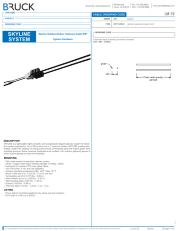
Application data (cont)Fan selection criteriaSystem requirementsThe major factors that influence fan selection are airflow,external static pressure, fan speed, brake horsepower, andsound level. Additional system considerations include thefan control method, overloading, and non-standard airdensity. Fan selection for air-conditioning service usuallyinvolves choosing the smallest fan that provides an acceptable level of performance, efficiency, and quality.Pressure considerationsThe static pressure is the resistance of the combined system apart from the fan. Contributors to static pressure include other components in the air handler, ductwork, andterminals. The static pressure is dependent on the airflowthrough the system, which is determined by the air conditioning requirements. As shown in the second fan law inthe table on the preceding page, the static pressure variesas the square of the airflow (cfm). This ratio between pressure and airflow determines the system curve for any airhandling system.The static pressure used to select a fan should be the pressure calculated for the system at design airflow. If the staticpressure is overestimated, the amount of increase in horsepower and air volume depends upon the steepness of thefan curves in the area of selection.With forward-curved (FC) fans, if the actual static pressureof the system is less than the design static pressure, the fanhas a tendency to deliver more air and draw correspondingly higher bhp (kW of energy). This higher current drawmay overload the motor and trip circuit breakers. This is acommon occurrence when FC centrifugal fans are operated before all the ductwork has been installed, or duringthe pull-down load on a VAV (variable air volume) system.StabilityFan operation is stable if it remains unchanged after aslight temporary disturbance, or if the fan operation pointshifts to another location on the fan curve after a slight permanent disturbance. Fan operation is unstable if it fluctuates repeatedly or erratically. There are 2 main types ofunstable fan operation:System surge is a cycling increase and decrease in systemstatic pressure.Fan stall is the most common type of instability, and itoccurs with any type of centrifugal fan when the fan isstarved for air.Normally, the rotation of the fan wheel forces the airthrough the blade passageway from the low pressure to thehigh pressure side of the fan. If the airflow is restricted toomuch, however, there is not enough air to fill the spacebetween the blades and the air distribution between theblades becomes uneven and erratic. Air can flow backwards through the wheel and the noise level is substantiallyincreased. If the fan runs in this condition for a long time,wheel failure is likely to occur.For a given speed, the operating point where a fan stalls isa function of the wheel geometry and wheel speed. In general, the stall point is within the range of 15 to 25% of theairflow obtained at free delivery.6Stability and VAV applications — Special considerations must be made for VAV systems. While the initial fanselection may be acceptable, its operating point could shiftto a point of stall at minimum airflow and pressure conditions. The typical minimum airflow is half of the designcooling airflow, which is also often equal to the heatingairflow. To determine and plot the minimum airflow versusstatic pressure, use the following equation. This equationsolves for the static pressure at a specific airflow based ona minimum static pressure set point:((((CFM1CFMDESIGN)27,50015,000)2X(SPDESIGN – SPMIN)X (4 – 2)) SP SP1MIN) 2 2.50 in. wgCFM — Airflow in Cubic Feet Per MinuteSP — Static PressureThe table below illustrates a system with an airfoil fanwheel at a cooling design of 15,000 cfm and a systemstatic pressure of 4 in. wg. The minimum airflow is7,500 cfm with a minimum system static pressure set pointof 2 in. wg. The minimum static set point is based onzero airflow and does not coincide with the minimum design airflow.Example:% 007,500SYSTEM AND FAN STATIC PRESSURE(in. wg)4.003.623.282.982.722.50As shown on the highlighted VAV curve, the minimum airflow and static pressure (MP) are both well within the acceptable operating conditions of the fan.VAV 416182022AIRFLOW (1000 CFM)MP — Minimum PointRP — Rated PointMSE — Maximum Static Efficiency SC — System Curve242628
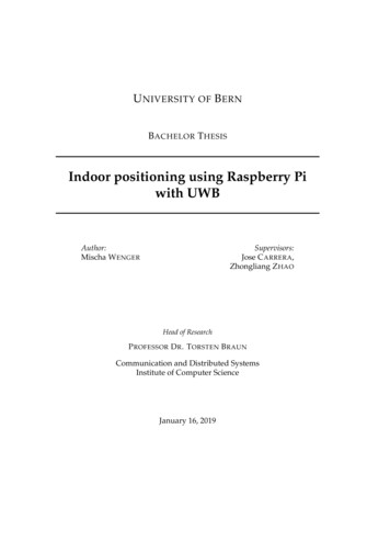
Application data (cont)Example:Forward-curved fan, 6,100 cfm, 1333 rpm, 5.8 bhp, selected with 100% 2 in. pleated filters. Dirty filters result ina total static pressure (TSP) of 3.56 inches.FORWARD-CURVED FAN7MSE6SC5TOTAL IN. WGSound considerations — The fan is one of the mainsound sources in an air-conditioning system. Other sourcesof sound include the duct system and terminals, becausethey generate turbulence in the air flowing through them.Simply estimating fan sound does not give an accuratepicture of total system sound, but because fan sound is amajor component of system sound, fan sound should beminimized.To minimize its sound generation, a fan must be correctlysized and should be selected to operate at or near peak efficiency. Oversized fans can generate much higher soundpower levels than necessary, especially in VAV systemsoperating at low airflows. Undersized fans can also result inhigher sound power levels because of increased fan speedsand the higher tip velocity of the air leaving the fan blades.For VAV systems, the part load point at which the fan operates most of the time should be used to select a fan forlowest sound output.Variable frequency drives (VFDs) are used to modulate fanvolume. A VFD reduces the sound power level as the fanspeed is reduced. At 50% load, the sound level isreduced approximately 15 dB compared to the sound level at100% load. When using variable frequency drives, it is important to be sure that the static deflection of the vibrationisolators is adequate. At very low fan speeds, the fan frequency may approach the natural frequency of the springisolation. If this happens, the vibration levels can be amplified and resonant vibration conditions can occur.When sound level is a major consideration, a blow-thru fanshould be considered because of the reduced dischargesound level. This sound reduction is due to the soundabsorption of the coil section downstream from the fan.Transition fittings and elbows can be reduced in size oreliminated, thereby eliminating a sound source.To obtain projected sound data for a selected 39S unit, usethe electronic catalog AHUBuilder program.Dirty filtration considerations — Consider selecting anair handler with dirty filters so that, in theory, the unit willhave enough horsepower to deliver the same amount of airwhen the filters are dirty. On a constant volume unit, thatwould only work if the unit contained an airflow measuringstation and could adjust the flow accordingly via a VFD.Otherwise, the point of operation moves along the RPMline as the static pressure in the system changes.What happens when the fan with sheaves selected fordirty filters is ordered? Three things:1. The air balancer forces the selection of a smallersheave because the airflow is too high. When thefilters load up, airflow is reduced.2. If an air balance is not performed, the cooling coilmay exhibit moisture carryover due to the considerable increase in airflow.3. The fan motor trips out on overload with the forwardcurved fan because of the increase in bhp.4RP3210LEGEND— —--- —MSE —RP —SC —024RPMBHPMax. Static Eff.Rated PointSystem Curve612810AIRFLOW (1000 CFM)141618RPM 1333BHP 5.8Max RPM 1600Max BHP 15.0RPM’s (x 100, L to R): 6, 7, 8, 9, 10,11, 12, 13, 14, 15, 16BHP’s (L to R): 1.5, 2, 3, 5, 7.5, 10,15, 20Clean filters result in a TSP of 3.06 in.Follow the 1333 rpm line down to 3.06 in.Clean filter cfm will be 8,500 cfm. Also note that thehorsepower goes from 5.8 bhp to about 9 bhp because theFC fan is an overloading type fan.So, if dirty filters need to be taken into consideration, doone of the following:1. Make the final fan selection with the clean filter rpmbut use the motor horsepower requirement for dirtyfilters.2. Make the final fan selection with the dirty filter rpmand use the motor horsepower requirement for dirtyfilters — only if the engineer plans on using a VFDand airflow measurement station or if it is a VAVsystem.Fan, motor, and drive heat considerations — Thework output of a fan and its motor and drive contributedirectly to the airflow and pressure exiting the air handler.Not all of the energy output of the fan generates airflow,however. Fan motors are not 100% efficient, and theirefficiency loss translates directly into heat that must befactored in when calculating the temperature rise across afan section. Fans also add a certain amount of heat to theairstream due to the effects of compression and bearingfriction. Finally, belt drives do not transmit all of the energygenerated by the motor. Some of the energy is lost in theform of heat due to belt tension and the type and numberof belts. Belt drive bhp losses range from 2 to 6 percent; a3% loss is typical.7
Application data (cont)Because the 39S Series air handlers all have their fans,motors, and drives located within the airstream, heat lossesfrom these components affect the power requirements,cooling load, and heating load.Power losses in the motor and drive should be allowed forwhen determining the motor output (bhp), so that the motor can be correctly sized and so that the additional heatoutput can be subtracted from cooling capacity or added toheating capacity. A typical example follows:Given Fan Operating Point:13,224 cfm9.6 Fan bhp3.0% estimated drive lossCalculate the required fan motor output (Hp) due to driveloss:Hp (Fan bhp) x (Drive Loss)Hp 9.6 x 1.03Hp 9.89 hp (select 10 Hp motor)Calculate the total fan motor heat output (Q) according tomotor efficiency:Q (Motor Output) (Motor Efficiency [Typical])Q 9.89 0.86Q 11.5 hpConvert horsepower to Btu per hour.11.5 hp x 2545 29,268 BtuhCalculate the increase in leaving-air temperature ( T) dueto fan and motor heat and drive losses:Q 1.1 x cfm x T29,268 Btuh 1.1 x 13,224 x T29,268 Btuh 14,546.4 x T T 2.01 F (use to estimate coil requirements)Fan applicationCertain fans are more efficient in low-static pressure systems, while others operate best in higher pressure systems.Some fan types are designed to handle very large air volumes while others are more efficient at lower volumes. Thelow cost 39S unit is designed for use with low-static pressure systems and is only available with forward-curved fans.For higher static applications, specify 39M or 39CC units.Forward-curved (FC) fans are typically used for low tomedium pressure applications (0 to 5 in. wg total staticpressure [TSP]).The FC fans are reasonably stable over a wide airflow (cfm)range at constant speed. Because of the relatively flatcurve, FC fans tolerate modulation in airflow without largeincreases in static pressure. Most important, FC fans arelowest in first cost.Plenum fans (sometimes called ‘‘plug’’ fans) are typicallyused in medium to high static pressure applications whereductwork requires discharge location flexibility. They canreduce the need for ductwork turns or diffusers, especiallywhen equipment room space is limited.Plenum fans are less efficient than double-width, double-inlet airfoil fans. General construction also differs from thatof FC or AF fans. The fan does not have a scroll to enclosethe fan wheel and direct airflow. Instead, the entire interiorof the plenum fan section is pressurized by the fan.8Plenum fans have single-width, single-inlet (SWSI) construction. The fan shaft is parallel with the airflow, and themotor and bearings are located inside the plenum in thepressurized airstream. An optional inlet screen and wheelcage can be installed to help protect personnel duringmaintenance.Plenum fans are generally used where there are space limitations, a need for discharge flexibility, a need for reduceddischarge sound, or where duct configurations mightchange in the future. For example, in an application wherethere is not enough room in the building for a large mainduct, several smaller duct runs may approach the mechanical equipment room from all sides. In such an application,several connections can be made to one or more sides ofthe plenum fan section. Installing contractors can cut outlets in the plenum box at the time of installation to suit theconditions at the jobsite.Because the casing of a plenum fan section acts as a soundattenuator, plenum fans are also sometimes used when discharge sound levels need to be reduced.Duct takeoffs from plenum fans can have relatively highpressure losses and can also create turbulence that causes alarger pressure drop across coil and filter sections. Whenselecting a plenum fan, the pressure drop for the duct takeoffs must be added to the external static pressure for therest of the system.To calculate the pressure losses from plenum fanduct takeoffs, use the following formula and referto the figure at right.Pl Pp - Pd (Cv) (Vp)Where Pl is the pressure loss, Pp is the plenum pressure, Pdis the duct pressure, Cv is the pressure loss coefficient, andVp is the velocity pressure in the duct. Note that for radialduct takeoffs, Cv is 1.5 in. wg, while for axial duct takeoffs,Cv is 2.0 in. wg. To calculate velocity pressure (Vp) in theduct, use the following formula, where V is the air velocityin the duct:Vp [(V) (4005)]2Also note that with more than one duct takeoff and different duct velocities, the highest duct velocity and highest Cvvalue should be used in the formulas.Duct design considerationsThe discharge ductwork immediately downstream from thefan is critical for successful applications. Poorly designedductwork can degrade fan performance and contributes toexcessive pressure drop and noise.The 39S Series forward-curved fans are tested as part of asystem with straight discharge ductwork, and the fanratings are based on this duct design. When designingductwork in the field, it is important to use a straight dischargeduct of the correct dimensions to obtain maximum fan performance. The straight section of ductwork helps the airflow todevelop a uniform velocity profile as it exits the fan and allowsthe velocity pressure to recover into static pressure. See thefigure on the next page.For 100% recovery of velocity pressure into static pressure, the straight portion of the discharge duct must be atleast 2-1/2 times the discharge diameter in length for
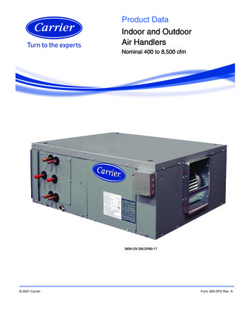
Application data (cont)velocities of 2500 fpm or less. For each additional 1000fpm, add one duct diameter to the length of the straightportion of the ductwork.As an example of how to size the straight portion of duct,assume the fan has a 34 x 34 in. discharge outlet(8.03 sq ft). The equivalent diameter is 39 in., so thestraight duct length required would be 8 ft long.Plenum fans do not require belts in the system. Therefore,users can expect improved efficiency.CUTOFFDISCHARGE DUCTCENTRIFUGALFANb. Compatibility with VAV control5. Sound levelsa. Fan-generated soundb. Terminal soundc. Control-generated soundd. System sound (ducts, fittings)6. Initial cost and operating cost7. Reliability and ease of maintenanceSystem parametersBefore a fan type or control is selected, the system must beanalyzed at both the design point and part load. The fan islikely to be operating at part load for a large percentage ofthe time.Methods of fan air-volume control100% EFFECTIVE DUCT LENGTH2 1/2 DIAMETERS AT 2500 FPMFan control on variable air volume systemsIntroductionWith their inherent characteristics of reducing airflow tomeet demand, VAV systems can be a source of major energy savings, because fan brake horsepower (bhp) varies withthe amount of air delivered.The degree to which bhp savings are realized, however, isalso affected by the type of fan volume control selected andthe effectiveness of its application. Effective fan control assures proper duct pressure for the required control stabilityof the air terminals and provides quiet terminal unit operation when “riding the fan curve.”Consider the following when selecting a fan volume controlmethod:1. System parametersa. Airflow (cfm)b. Static pressurec. Percent volume reduction (turndown)2. Fan type and selection pointa. Design point efficiencyb. Part load efficiency (especially the point where thefan will be operating most of the time)c. Part load stability3. Ease of control installation and use4. Motor selectiona. Higher bhp inputs due to efficiency of VAV control method “Riding the fan curve” with terminal throttling (forwardcurved fans) Variable frequency drives (VFDs)A short description of these control methods follows. Asummary comparison table is provided at the end of thesection.Forward-curved (FC) fans with terminal throttling(riding fan curve) — This is the simplest, most reliable,and most economical first-cost method of air volume control on VAV systems, since no accessories are required.This type of VAV control can be used on forward-curvedfans with flat pressure characteristics and in systems wherestatic pressure changes at the terminals are moderate. Airvolume reduction is produced solely by throttling of terminal units in response to load reduction. As the units throttle, system resistance changes.The chart below, Forward-Curved Fan with Air TerminalThrottling, illustrates the reduction in bhp and airflow atconstant speed. Point A is the peak airflow operatingpoint. Note the required bhp at this airflow. As airflow isreduced by terminal throttling, move along the fan constant rpm curve to point B. Note the lower cfm and bhpvalues at B.At reduced airflow conditions, the total system static pressure may undergo little or no change, although air pressureloss through the air-handling unit decreases. This meansthat duct pressure increases as pressure loss across the terminal unit increases. For low-static and medium- staticpressure systems, this increase in duct pressure should notresult in noticeable sound level changes. However, at higher design static pressures, sound levels and duct leakagemay increase and the control method should be reviewedto determine if it is feasible.9
Application data (cont)FAN TYPE AND APPLICATIONTYPEForward-Curved(FC)Side ViewPlenum(PAF)End ViewCHARACTERISTICSAPPLICATION Double-width, double-inlet (DWDI) construction. Best at low or medium pressure (approximately0 to 5 in. wg). Horsepower increases continuously withincrease in air quantity (overloads) as static pressuredecreases. Runs at relatively low speed, typically 400 to 1200 rpm. Blades curve toward direction of rotation.For low to medium pressure air-handlingapplications. Single-width, single-inlet (SWSI) construction. Characteristics similar to DWDI airfoil fan. Blades have aerodynamic shape similar toairplane wing and are curved away from directionof rotation. Fewer blades and wider bladespacing than AF fans.Best in applications with limited space ormultiple ducts.FORWARD-CURVED FAN WITH AIR TERMINAL THROTTLING VARIATIONS IN BHP AT CONSTANT RPM10
Application data (cont)Variable frequency drivesVariable frequency drives (VFDs) are used to modulate thefan motor speed in response to air volume requirements.To vary the motor speed, a VFD changes the input frequency and line voltage into a wide range of frequency andvoltage outputs, while maintaining a constant ratio of frequency to voltage.Variable frequency drives convert input ac power to dcpower and then convert the dc power to a different acpower output using an i
Central station air handler The central station air handler is a heating, ventilating, or air-conditioning unit that is centrally located in, or on, a building or structure and from which air is distributed to desired areas through a system of ducts. The 39S factory packaged unit Individual components, such as fans, coils, and filters, are