Transcription
MMVEINSTALLATION MANUALMODULAR AIR HANDLER WITH ELECTRIC OR HOT WATER HEATINGMODELS: MM SERIESLIST OF SECTIONS1 – General2 – Safety3 – Return Air and Clearance Requirements4 – Supply Air and Duct Connector Installation5 – Furnace Installation6 – Hydronic Heating1257887 – Line Voltage and Control Box Wiring8 – Field Installed Electric Heater Kits9 – Thermostat Wiring and Connections10 – Motor, Blower and Furnace Startup11 – Final System Checkout12 – Wiring Diagrams121617222425LIST OF FIGURES1 – Electric Air Handler Dimensions2 – Hydronic Air Handler Dimensions3 – Clearance for Service4 – Closet Clearances5 – Typical Closet Installations6 – Accessory Air Filter Box for 1” or 2” Air Filters7 – Combustible Floor Base Installation - Downflow8 – Component Locations – Electric Heat Control Box9 – Component Locations – No Heat Control Box10 – Component Locations – Hydronic Heat No Pump11 – Component Locations – Hydronic Heat With Pump12 – Control Box Circuit Breaker Location13 – Front Panel Circuit Breaker Location14 – No Heat & Electric Heat Control Box Power Connections15 – Hydronic Control Box Power Connection Locations16 – 1 Stage Heating / Cooling Wiring Diagram17 – 1 Stage Heating / Cooling Wiring Diagram18 – 1 Stage Heating / Heat Pump Wiring Diagram19 – 1 Stage Heating / Heat Pump Wiring Diagram445667815151515161617171819191920 – 2 Stage Heating / Cooling Wiring Diagram21 – 2 Stage Heating / Cooling Wiring Diagram22 – 2 Stage Heating / Heat Pump Wiring Diagram23 – 2 Stage Heating / Heat Pump Wiring Diagram24 – X-13 motor Terminals25 – Blower Mounting Plate and Screw Locations26 – Blower Assembly and Blower Deck27 – ECM Motor Control Plug Pin out28 – ECM Control Board Diagram29 – MMVE 18-72 – 0 kW Heater Wiring Diagram30 – MMVE 18-72 – 5 kW Heater Kit Wiring Diagram31 – MMVE 25-72 – 10 kW Heater Kit Wiring Diagram32 – MMVE 37-72 – 15 kW Heater Kit Wiring Diagram33 – MMVE 37-72 – 20 kW Heater Kit Wiring Diagram34 – MMVE 18-36 – Hydronic Heat w/ Pump No Choke Wire Dia35 – MMVE 37-72 – Hydronic Heat w/ Pump and Choke Wire Dia36 – MMVE 18-36 – Hydronic Heat No Pump or Choke Wire Dia37 – MMVE 37-72 – Hydronic Heat w/ Choke No Pump Wire Dia192020202222232324252626272728282929LIST OF TABLES1 – Electric / Hydronic Air Handler Model Specifications2 – Electric Air Handler Dimensions Table3 – Hydronic Air Handler Dimensions Table4 – Air Handler Model Nomenclature5 – Clearance to Combustibles6 - Htg Cap Boiler Loop 65 F EAT 180 F EAT 20 F Δt No Pump7 - Htg Cap Boiler Loop 65 F EAT 180 F EAT 20 F Δt No Pump8 - Htg Cap Boiler Loop 65 F EAT 180 F EAT 20 F Δt No Pump9 – Htg Cap Factory Pump 65 F EAT Stated EAT 1.5 and 2 Ton10 – Htg Cap Factory Pump 65 F EAT Stated EAT 2, 2.5 and 3 Ton11– Htg Cap Factory Pump 65 F EAT Stated EAT 3, 3.5, 4 & 5 Ton12 – Wiring Requirements–115V Hydronic Single Branch Circuit344568991010111213 – Wiring Requirements–115V Hydronic Single Branch Circuit1314 – Wiring Requirements–208/240V Electric Single Branch Circuit 1315 – Wiring Requirements–208/240V Electric Single Branch Circuit 1316 – Wiring Requirements–208/240V Electric Duel Branch Circuit 1417 – Wiring Requirements–208/240V Electric Duel Branch Circuit 1418 – Electric Heater Electrical Data1419 – Accessory Field Installed Electric Heater Kit Model Numbers 1620 - Accessory Field Installed Electric Heater Kit Nomenclature1721 – Low Voltage Wire Gauge and Max lengths1722 – Recommended Heating / Cooling /Heat Pump Wire Color Codes 2123 – X-13 Motor Terminal Connections2224 – ECM Motor Control Connector Terminal Description23SECTION I: GENERALThe following list includes important facts and informationregarding the electric furnace and its inclusions.1. Air handler is rated at either 120 volts AC or 240 volts AC at60 Hertz2. Air handler size varies by model3. Four-wire thermostat operation for heating and cooling4. Seven wire thermostat for heat pump operation.5. Air Handlers equipped with blower for A/C or Heat Pumpoperation6.This air handler is designed for multi position, upflow andhorizontal application7. This air handler must not be operated without the doorinstalledNOTE: This air handler and its components listed on the A/C andHeat Pump equipment sticker were listed in combination as asystem by ETL for the United States and Canada.SAVE THIS MANUAL FOR FUTURE REFERENCEMORTEX PRODUCTS INC. 501 TERMINAL RD FORT WORTH, TEXAS 76106Page 1
This product must be installed in strict compliance with theinstallation instructions and any applicable local, state, andnational codes including, but not limited to; building,electrical, and mechanical codes.IMPORTANTThe Clean Air Act of 1990 bans the intentional venting ofrefrigerant (CFC's and HFC's) as of July 1, 1992. Approvedmethods of reclaiming must be followed. Fines and/orincarceration may be levied for non-complianceSafety RequirementsSECTION II: SAFETYThis is a safety alert symbol. When you see this symbol onlabels or in manuals; be alert to the potential for personal injury.Understand and pay particular attention to the signal wordsDANGER, WARNING, or CAUTION.DANGER: indicates an imminently hazardous situation, which ifnot avoided, will result in death or serious injury.WARNING: indicates a potentially hazardous situation, which ifnot avoided, could result in death or serious injury.CAUTION: indicated a potentially hazardous situation, which ifnot avoided, may result in minor or moderate injury. It is alsoused to alert against unsafe practices and hazards involvingproperty damage.Improper installation may create a condition where theoperation of the product could cause personal injury orproperty damage.Improper installation, adjustment, alteration, service ormaintenance can cause injury or property damage. Refer tothis manual for assistance; or for additional informationconsult a qualified contractor, installer, or service agency.FIRE OR ELECTRICAL HAZARDFailure to follow the safety warnings exactly could result inserious injury, death, or property damage.A fire or electrical hazard may result causing propertydamage, personal injury or loss of life.This appliance should be installed in accordance with allnational and local building/safety codes and requirements, localplumbing or waste water codes, and other applicable codes. Inthe absence of local codes, install in accordance with thefollowing codes. Standard for the Installation of Air Conditioning andVentilating Systems (NFPA 90A) Standard for the Installation of Warm Air heating andAir Conditioning Systems (NFPA 90B) National Electrical Code (NFPA 70) Canadian Electrical Code, Part I (CSA C22.2) orANSI/NFPA No. 70 All local codes (State, City, and Township)NOTE: All applicable codes take precedence over anyrecommendation made in these instructions.SunTherm assumes no responsibility for units installed inviolation of any code or regulation.1. Refer to the unit rating plate for the air handler modelnumber, and then see the dimensions page of thisinstruction for return air plenum dimensions in Figures 1and 2. The plenum must be installed according to the abovelisted codes or the instructions in this manual.2. Refer to the dimensions page of this instruction for the ductconnector and combustible floor base dimensions shown inFigure 7. The duct connector and combustible floor basemust be installed according to the instructions in thismanual.3. These models ARE NOT ETL listed or approved forinstallation into a Manufactured (Mobile) Home.4. Provide clearances from combustible materials as listedunder Clearances to Combustibles.5. Provide clearances for servicing ensuring service access isallowed for the control box, electric elements, hot watercoil and the blower.Hot water from a boiler used to satisfy heating requirementscan be heated to temperatures of 180 F. Parts containingwater this hot can scald very quickly. Use extreme cautionwhen servicing or performing maintenance on any partscontaining hot water.MORTEX PRODUCTS INC. 501 TERMINAL RD FORT WORTH, TEXAS 76106Page 2
6.7.8.9.10.11.12.13.14.15.Check the rating plate and the power supply to be sure theelectrical characteristics match.Failure to carefully read and follow all instructions in thismanual can result in malfunction of the air handler, death,personal injury, and/or property damage.Electric air handler shall be installed so the electricalcomponents are protected from water.Installing and servicing heating/cooling equipment can behazardous due to electrical components.Only trained and qualified personnel should install repair orservice heating/cooling equipment. Untrained servicepersonnel can perform basic maintenance functions such ascleaning of exterior surfaces and replacing the air filters.Observe all precautions in the manuals and on the attachedlabels when working on this appliance.These instructions cover minimum requirements andconform to existing national standards and safety codes. Insome instances these instructions exceed certain local codesand ordinances, especially those who have not kept up withchanging home and/ or HUD construction practices. Theseinstructions are to be followed and are the minimumrequirement for a safe installation.The size of the unit should be based on an acceptable heatloss calculation for the structure. ACCA, Manual J or otherapproved methods may be used.Check the rating plate and power supply to be sure that theelectrical characteristics match. The 115 VAC models usenominal 115 VAC, 1 Phase, 60-Hertz power supply. DONOT CONNECT THIS APPLIANCE TO A 50 HZPOWER SUPPLY OR A VOLTAGE ABOVE 130VOLTS.The 240 VAC models use nominal 240 VAC, 1 Phase, 60Hertz power supply. DO NOT CONNECT THISAPPLIANCE TO A 50 HZ POWER SUPPLY OR AVOLTAGE ABOVE 250 VOLTS.Ground connections MUST BE securely fastened to thecontrol box and ground wires MUST BE secured to theground lugs control box with terminals.ALWAYS SHUT OFF ELECTRICITY AT THEDISCONNECT SWITCH OR TURN OFF THE CIRCUITBREAKERS IN THE MAIN ELECTRICAL ENTRANCEBEFORE PREFORMING ANY SERVICE ON THEAPPLIANCE.GENERAL INFORMATIONThis single piece air handler provides the flexibility forinstallation in any upflow, downflow, or horizontal application.The versatile models may be used with or without electric heator hot water heat. The direct drive variable speed ECM motor,optional (3) speed PSC motor, or the (5) five speed X-13motors provide a selection of air volume to match anyapplication.The unit can be positioned for bottom air return in the upflowposition, top air return in the downflow position, or air returnthrough the end of the unit in the horizontal position.NOTE: Refer to the instructions in this manual for the properdownflow conversion kit and instructions on the properconversion to downflow.InspectionAs soon as the furnace is received, it should be inspected forpossible damage during transit. If damage is evident, the extentof the damage should be noted on the carrier’s freight bill. Aseparate request for inspection by the carrier’s agent should bemade in writing. Before installing the air handler you shouldcheck the cabinet for screws or bolts which may have loosenedin transit. There are no shipping or spacer brackets which needto be removed before startup.See local Distributor for more information. Mortex Products,Inc assumes no liability for freight damage.Also check to be sure all accessories such as heater kits, andcoils are available. Installation of these accessories should beaccomplished before the air handler is set in place or theconnecting of the wiring, electric heat, ducts or piping.Electric HeatModelsMM**18,24 MM**25,30,36 MM**37,42,48,60MM**72Input, kW5,105,10,155,10,15,205,10,15,20Blower Size-Heat (D x W )9 X610 X 712 X 912 X 10Unit Voltage240V, 60 HZ, 1 PH0.50Max. External SP (Duct), In. W .C.24 VAC, 60 Hz, 40VAThermostat CircuitHydronic HeatModelsHot W ater Coil (Rows)Blower Size-Heat (D x W )MM**18,24 MM**25,30,36 MM**37,42,48,60MM**722,32,3,42,3,42,3,410 X 710 X 712 X 912 X 10Unit Voltage115V, 60 HZ, 1 PHMax. External SP (Duct), In. W .C.Thermostat Circuit0.5024 VAC, 60 Hz, 40VATable 1 Air Handler Model SpecificationsAvailable Blower Motors1. Standard Blower Motor - – VAR SPD ECM MOTOR2. Optional Blower Motor - 3 SPD PSC MOTOR3. Optional Blower Motor – 5 SPD X-13 MOTORMORTEX PRODUCTS INC. 501 TERMINAL RD FORT WORTH, TEXAS 76106Page 3
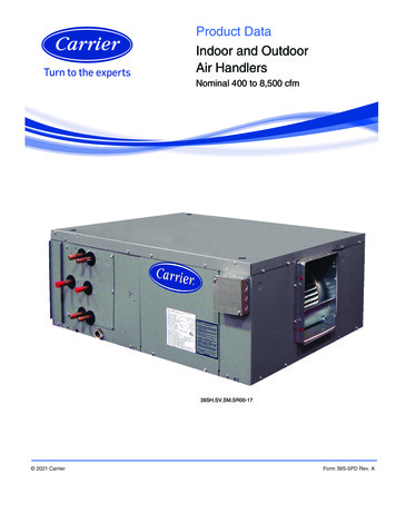
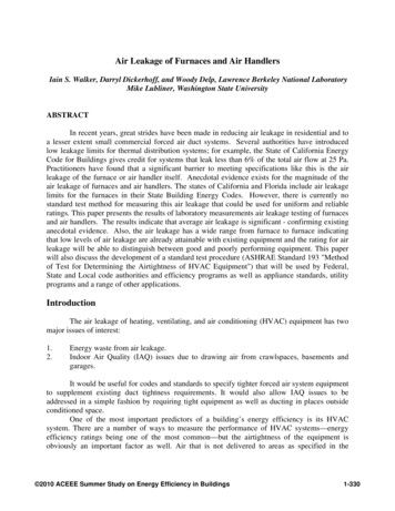
Figure 1: DIMENSIONAL DATA MODULAR ELECTRIC HEATModelMM**18, 24MM**30, 36MM**37, 42, 48, 60, e 2: DIMENSIONAL DATA MODULAR ELECTRIC HEATDIMENSIONAL DATA MODULAR HYDRONIC HEATFigure 2: DIMENSIONAL DATA MODULAR HYDRONIC HEATModelMM**18, 24MM**30, 36MM**37, 42, 48, 60, 72ModelMM**18, 24MM**30, 36MM**37, 42, 48, 60, 8753.8754.25H5.755.756.00I2.502.502.50Table 3: DIMENSIONAL DATA MODULAR HYDRONIC HEATMORTEX PRODUCTS INC. 501 TERMINAL RD FORT WORTH, TEXAS 76106Page 4
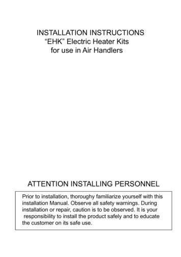
SeriesMotor TypeUnit SizeCapacity inMBTU/HHeatingConfigurationVoltageOption CodeAA Standard ConfigurationXX Motor Program CodeXX Pre-Painted Grey Top &Front Embossed GalvanizedXX Standard CoilXX 1" InsulationMM Multi-position ModularPS Standard PSCVT Variable Speed X-13VE Variable Speed ECMA 120 VAC, 1 PH, 60 HZB 208/230 VAC, 1 PH, 60 HZContact factory For Other VoltageAvailibilitySmall Cabinet 18, 18OS, 24, 24OSMedium Cabinet 25, 25OM, 30,30OM, 36, 36OMLarge Cabinet 37, 37OL, 42. 42OL,48, 48OL, 60, 60OL,72, 72OL0 0kW No Heat5 5kW Electric Heat10 10kW Electric Heat15 15kW Electric Heat20 20kW Electric Heat2P 2 Row HW Coil with Pump3P 3 Row HW Coil with Pump4P 4 Row HW Coil with Pump2N 2 Row HW Coil No Pump3N 3 Row HW Coil No Pump4N 4 Row HW Coil No PumpTable 4: Air Handler Model NomenclatureNOTE 1: Electric heaters may be factory or field installed.NOTE 2: MM Multiposition Modular “Heating Only”.FILTER BASE ASSEMBLY KIT – FIELD INSTALLED86ET0002 – 16”X 20” X 2” Small Cabinet, 86ET0001 – 20” X 20” X 2” Medium Cabinet, 86ET0003 – 20” X 24” X 2” Large CabinetSECTION IlI: CLEARANCE AND RETURNAIR REQUIREMENTSLOCATIONAccess for servicing is an important factor in the location of anyair handler. Provide a minimum of 30 inches in front of theappliance for access to the control box, heating elements, waterpump, blower and air filters. This access may be provided by acloset door or by locating the appliance so that a wall orpartition is not less than 30 inches from the front access PanelLocation is usually predetermined. Check with owner’s ordealer’s installation plans. If location has not been decided,consider the following in choosing a suitable location.1. Select a location with adequate structural support, space forservice access, clearance for return and supply ductconnections.2. Normal operating sound levels may be objectionable if theair handler is placed directly over or under some roomssuch as bedrooms, study, etc.3. Caution should be taken to locate the unit so that supplyand return air ducts are about the same length causing evenair distribution of supply and return air to and from theliving spaces.4. Locate appliance where electrical supply wiring can beeasily routed to main electrical panel and where electricalwiring will not be damaged.5. Locate appliance where thermostat wiring can be easilyrouted to the thermostat and where the wiring will not bedamaged.6. Some states, cities and counties require additionalinsulation to be installed on the exterior casing of the airhandler to prevent sweating. Refer to the state, city, countyor local code for insulation requirement to be sure theinstallation is in compliance.It is recommended that air handlers installed in nonconditioned spaces be insulated on the exterior of the entirecabinet, including the front access panel with one (1) inchthick fiberglass with the vapor barrier on the outside.Appliance ClearancesThis appliance is approved for zero (0) inches clearance tocombustible material on any part of the air handler exteriorcasing and the inlet or outlet ducts providing NO electric heateris being used. There is a one (1) inch clearance on the supplyplenum and supply air duct when an electric heater is installedin the appliance. Refer to Table 5 for clearance to combustiblesinformation.30”Figure 3: Clearance – Access for ServiceMORTEX PRODUCTS INC. 501 TERMINAL RD FORT WORTH, TEXAS 76106Page 5
MODELHydronicElectricTOP (in)00BACK (in)00FRONT OF FURNACESIDES (in) ALCOVE (in) CLOSET (in) DUCT (in)0306003061Table 5: Clearances to CombustiblesyyFigure 4: Closet ClearancesMinimum 430 in² free area openingUse Return Grille, or A/C Coil Cabinet, or any returngrille with a minimum 430 in² free area openingBottom Return Only – Recommended Grille Size800 CFM – 20 X 20 Grille – 324 in²1000 CFM – 20 X 25 Grille - 414 in²1200 CFM – 25 X 25 Grille - 414 in²1400 CFM – 25 X 30 Grille - 644 in²1600 CFM – 25 X 30 Grille - 644 in²1800 CFM – 30 X 30 Grille - 784 in²2000 CFM – 30 X 35 Grille - 924 in²2400 CFM – 30 X 40 Grille - 1064 in²The return air opening can be located in in the floor, on a closetfront door or in a side wall above the furnace casing. If openingfor the return air is located in the floor, side walls, or closet dooranywhere below the appliance casing, a 6 inch minimumclearance between the appliance and the wall or door must beprovided on the side where the return is located to provide forproper air flow. The 6 inch minimum clearance is not required ifthere is a return grille installed above the appliance casing,providing the grille has a sufficient return air opening.CLOSET WALLSReturn AirIn order for the air handler to work properly, a closet or alcovemust have a certain total free area opening for the return air.For Air Handlers with a 1/3 HP Blower Motor On (MMVE,MMVT, MMPS 18 and 24 models)y Minimum 200 in² free area openingy Use Return Grille or Coil CabinetFor Air Handlers with a 1/2 HP Blower Motors On (MMVE,MMVT, MMPS 25, 30, and 36 models)y Minimum 250 in² free area openingy Use Return Grille, A/C Coil Cabinet, or any returngrille with a minimum 250 in² free area openingFor Air Handlers with Electric Heat that use a 3/4 HPBlower Motor On (MMVE, MMVT, MMPS 37, 42, 48, and60 models)y Minimum 390 in² free area openingy Use Return Grille, or A/C Coil Cabinet, or any returngrille with a minimum 390 in² free area openingFor Air Handlers with Hydronic Heat that use a 1.0 HPBlower Motor On (MMVE 37, 42, 48, and 60 models)y Minimum 390 in² free area openingy Use Return Grille, or A/C Coil Cabinet, or any returngrille with a minimum 390 in² free area openingFor Air Handlers with hydronic heat that use a 3/4 HPBlower Motor On (MMPS 37, 42, 48, and 60 models)y Minimum 390 in² free area openingy Use Return Grille, or A/C Coil Cabinet, or any returngrille with a minimum 390 in² free area openingFor Air Handlers that use a 1.0 HP Blower Motor On(MMVE, MMVT 72 models)Figure 5: Typical Closet InstallationsProvisions shall be made to permit the air in the rooms and theliving spaces to return to the furnace. Failure to comply maycause a reduction in the amount of return air available to theblower, causing reduced air flow resulting in improper heatingof the living space. The reduced air flow may cause the furnaceto cycle on the limit causing premature heating element failure.Upflow Accessory Filter Box KitAccessory filter box kit can be used on the return air end of theair handler when configured in the upflow position. The filter kitis placed over the return plenum in the floor and sealed to theplenum using sealant or caulking material and/or tape. The AirHandler is placed on top of the return filter box and the returnopening sealed to prevent leaks.MORTEX PRODUCTS INC. 501 TERMINAL RD FORT WORTH, TEXAS 76106Page 6
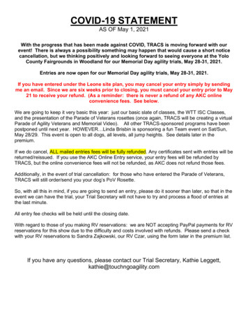
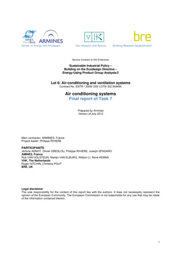
Accessory filter box kit can be used on the return air end of theair handler when configured in the downflow position in placeof a wall, door or ceiling mounted return filter grille.with screws. The unit is placed on top of the filter base andsecured to the base with screws. Use seal strip, tape or calkingto seal between the unit and the base.NOTE: Make sure the flow arrow on the air filter is pointingtowards the coil.Connect the supply air outlet to a plenum to the top of the unitand secure it with screws. Use a Non-tape sealant such as masticor an aerosol sealant to seal duct leakage.If installed in a basement, run supply and return duct work inaccordance with local codes. Use a Non-tape sealant such asmastic or an aerosol sealant to seal duct leakage.Figure 6: Accessory Air Filter Box for 1” or 2” AirFilters. Filter Size Adjustment knob is on both sidesSECTION IV: FURNACE & SUPPLY AIRDUCT INSTALLATIONAIRFLOW CONFIGURATION:Unit is shipped from the factory arranged to be installed in anupflow or horizontal right to left air flow position. Horizontalright to left means, when facing the front of the unit, when theunit is laid on its side, the supply air opening is to the left andthe return opening is to the right. These models are fieldconvertible to a horizontal left to right air flow positionUPFLOW APPLICATION:In an upflow installation the discharge outlet is at the top.Normal upflow installation will be in a closet or basement. Ifinstalled in a closet, the closet should have a platform framed in,that with an opening at the top of the platform centered in thecloset that measure at least 12 inches in height. A filter frameand filter can be used that covers the opening and is sealed toprevent air by-passing the filter. A filter grille can be used that islocated as described in RETURN AIR REQUIREMENTS. Theminimum filter size is shown in the table below.Standard Throw away Air Filter @ 300 ft/min or less800 CFM 20 x 20 x 11000 CFM 20 x 25 x 11200 CFM 20 x 30 x 11400 CFM 25 x 30 x 11600 CFM 25 x 30 x 11800 CFM 30 x 30 x 12000 CFM 30 x 40 x 1 or two 30 x 20 x 12400 CFM 30 x 40 x 1 or two 30 x 20 x 1HORIZONTAL APPLICATIONHorizontal applications will normally be used in an attic orcrawl space. This type of installation requires supply air plenumor duct to be connected to the supply collar and a return airplenum or duct be attached to the unit inlet collar. The supplyducts will be connected to the supply air plenum and routed thruthe attic to a register in each room. Use a Non-tape sealant suchas mastic or an aerosol sealant to prevent leaks in the ducts andthe plenum.The opposite end of the return air duct is attached to a returnfilter grille housing. The filter grille is usually located in a wall,just below the ceiling or the ceiling in a hallway. Use a Nontape sealant such as mastic or an aerosol sealant to prevent leaksin the ducts and the plenum.The unit is shipped to be installed without modification in aright to left configuration. See AIRFLOW CONFIGURATIONfor details.DOWNFLOW APPLICATION:The unit is designed for downflow configuration.Flip the unit so the top is now the bottom of the unit.INSTALLATION ON COMBUSTIBLE FLOORINGCombustible Floor Base MUST BE USED when the unit isbeing installed on combustible flooring. The unit cannot beinstalled on carpeting.Failure to use the combustible floor base combustibleflooring or installing the unit on carpeting could result in afire causing personnel injury, property damage or loss oflife.Before installing the combustible floor base make sure that thereis a minimum of R-12 insulation between the sheet metal andany wood or combustible flooring. Refer to Figure 7 for typicalcombustible floor base installation.Pleated Air Filter @ 500 ft/min or less800 CFM 16 x 16 x 11000 CFM 18 x 20 x 11200 CFM 20 x 20 x 11400 CFM 20 x 20 x 11600 CFM 20 x 25 x 11800 CFM 20 x 30 x 1 or two 20 x 15 x 12000 CFM 20 x 30 x 1 or two 20 x 15 x 12400 CFM 25 x 30 x 1 or two 14 x 30 x 1Pleated filters are not recommended for use with PSC Motors.The other option is to use the SunTherm Filter Base AccessoryKit. This filter base is placed on the closet floor and securedMORTEX PRODUCTS INC. 501 TERMINAL RD FORT WORTH, TEXAS 76106Page 7
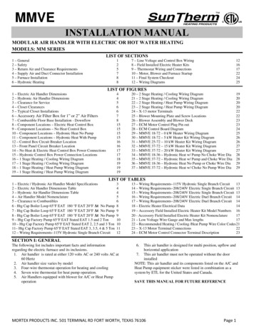
B. If the Combustible Floor Base is not used you secure theunit to the floor by drilling two holes through the furnacebase at the left and right front inside corners of the cabinet.Use two screws to secure the unit to the floor.6. Use calking, sealers, and/or tape to seal between thecombustible floor base and the opening on the unit orbetween the opening on the unit and the duct in the floor.7. Connect the electrical supply wires and the thermostatcontrol wires in the control box.8. Re-install the blower and control box access panel (door)and secure with the screws that were removed in step 29. Turn the power on to the unit by following the procedure inthe Users Information Manual.10. Set the thermostat to the desired temperature.Figure 7: Combustible Floor Base InstallationSECTION VI: HYDRONIC HEATINGSECTION V: FURNACE INSTALLATIONWater PipingInstalling the Air HandlerCloset InstallationPrior to installing the furnace make sure the holes are cut intothe floor for the refrigerant tubing, the drain line, the electricalwiring, the thermostat wiring and the condenser control wiring.1. Remove the top shipping cover and corner posts.2. Remove the bottom shipping cover.3. Remove the blower and control box access panel (door).4. Place the unit into position using one of the followingchoices:A. If the Combustible Floor Base is used you slide the unit onto the combustible floor base until the unit is touching theflanges on the back of the floor base.B. If the Combustible Floor Base is not used you slide the unitover the duct opening until the opening in the unit lines upwith the duct opening in the floor.5. Secure the unit by one of the two choices:A. If the Combustible Floor Base is used you secure thefurnace to the floor by drilling two holes through thefurnace base and the floor base at the right and left frontinside corners of the cabinet. Use two screws to secure thefurnace to the floor.All piping must be supported independent of coils to preventvibration and stress on coil headers. Swing joints or flexiblefittings must be provided to absorb expansion and contractionstrains. Rigid piping reduces the effectiveness of vibrationisolators. Coil water pipes must be adequately vented in order toprevent air binding. Units are provided with manual air ventsmounted through the manifold panel.Hot Water Piping:If a residential water heater is used for space heating water, do not exceed a distance of 70’ between the air handler and the water heater.The water heater should be the quick recovery type. Air handler and water heater must be located indoors and not subject to ,700LAT 4127.6125.7LWT OWSFPI231023Table 6: Hot Water Capacity-Boiler Loop 65 F EAT 180 F EWT 20 F Δt (No Pump) Small Cabinet 1.5 and 2.0 TonMORTEX PRODUCTS INC. 501 TERMINAL RD FORT WORTH, TEXAS 76106Page 8
1,08078,83089,45599,230LAT 2104.8128.0124.4121.4137.7133.7130.4LWT 76.6ROWSFPI23423104234Table 7: Hot Water Capacity-Boiler Loop 65 F EAT 180 F EWT 20 F Δt (No Pump) Med Cabinet 2.0, 2.5, 3.0 ,700143,400147,400155,600LAT 15.1113.3128.9126.8124.8LWT 04234234Table 8: Hot Water Cap-Boiler Loop 65 F EAT 180 F EWT 20 F Δt (No Pump) Large Cabinet 3.0, 3.5, 4.0, 5.0 TonMORTEX PRODUCTS INC. 501 TERMINAL RD FORT WORTH, TEXAS 76106Page 9
600800900600800900GPM4BTUH120 7,81020,17023,40024,800BTUH130 1,28024,00027,90029,500BTUH140 F18,84020,66022,23025,00027,84030,280
1. Air handler is rated at either 120 volts AC or 240 volts AC at 60 Hertz 2. Air handler size varies by model 3. Four-wire thermostat operation for heating and cooling 4. Seven wire thermostat for heat pump operation. 5. Air Handlers equipped with blower for A/C or Heat Pump operation 6. This air handler is designed for multi position, upflow and