Transcription
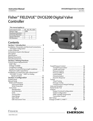
Instruction ManualDVC6200 Digital Valve ControllerD103605X012April 2022Fisher FIELDVUE DVC6200 Digital ValveControllerThis manual applies toInstrument LevelHC, AD, PD, ODVDevice Type1309Hardware Revision2Firmware Revision7Device Revision1 3DD Revision7 1ContentsSection 1 Introduction . . . . . . . . . . . . . . . . . 3Installation, Pneumatic and Electrical Connections, and Initial Configuration . . . . . . . . . . . . . . . . . . . . .Scope of Manual . . . . . . . . . . . . . . . . . . . . . . . . . . . . . .Conventions Used in this Manual . . . . . . . . . . . . . . . .Description . . . . . . . . . . . . . . . . . . . . . . . . . . . . . . . . . .Specifications . . . . . . . . . . . . . . . . . . . . . . . . . . . . . . . .Related Documents . . . . . . . . . . . . . . . . . . . . . . . . . . .Educational Services . . . . . . . . . . . . . . . . . . . . . . . . . . .3333558W9713Section 2 Wiring Practices . . . . . . . . . . . . . . 9Control System Requirements . . . . . . . . . . . . . . . . . . 9HART Filter . . . . . . . . . . . . . . . . . . . . . . . . . . . . . . . . . 9Voltage Available . . . . . . . . . . . . . . . . . . . . . . . . . . . . 9Compliance Voltage . . . . . . . . . . . . . . . . . . . . . . . . 11Auxiliary Terminal Wiring Length Guidelines . . . . 12Maximum Cable Capacitance . . . . . . . . . . . . . . . . . 12Installation in Conjunction with a Rosemountt 333 HART Tri‐Loopt HART‐to‐Analog Signal Converter . . . . . . . . . . . . . . . . . . . . . . . . . 13Section 3 Configuration . . . . . . . . . . . . . . . 15Guided Setup . . . . . . . . . . . . . . . . . . . . . . . . . . . . . . .Manual Setup . . . . . . . . . . . . . . . . . . . . . . . . . . . . . . .Mode and Protection . . . . . . . . . . . . . . . . . . . . . . . .Instrument Mode . . . . . . . . . . . . . . . . . . . . . . .Write Protection . . . . . . . . . . . . . . . . . . . . . . . .Instrument . . . . . . . . . . . . . . . . . . . . . . . . . . . . . . . .Identification . . . . . . . . . . . . . . . . . . . . . . . . . . .Serial Numbers . . . . . . . . . . . . . . . . . . . . . . . . .Units . . . . . . . . . . . . . . . . . . . . . . . . . . . . . . . . . .Terminal Box . . . . . . . . . . . . . . . . . . . . . . . . . . .Input Range . . . . . . . . . . . . . . . . . . . . . . . . . . . .Spec Sheet . . . . . . . . . . . . . . . . . . . . . . . . . . . . .Edit Instrument Time . . . . . . . . . . . . . . . . . . . essure Control . . . . . . . . . . . . . . . . . . . . . .Travel/Pressure Select . . . . . . . . . . . . . . . . . . .Cutoffs and Limits . . . . . . . . . . . . . . . . . . . . . . .Pressure Control . . . . . . . . . . . . . . . . . . . . . . . .Pressure Fallback . . . . . . . . . . . . . . . . . . . . . . . .Control Mode . . . . . . . . . . . . . . . . . . . . . . . . . .Characterization . . . . . . . . . . . . . . . . . . . . . . . .Dynamic Response . . . . . . . . . . . . . . . . . . . . . .Tuning . . . . . . . . . . . . . . . . . . . . . . . . . . . . . . . . . . . .Travel Tuning . . . . . . . . . . . . . . . . . . . . . . . . . . .Pressure Tuning . . . . . . . . . . . . . . . . . . . . . . . .Travel/Pressure Integral Settings . . . . . . . . . .Valve and Actuator . . . . . . . . . . . . . . . . . . . . . . . . . .Partial Stroke Test . . . . . . . . . . . . . . . . . . . . . . . . . .Outputs . . . . . . . . . . . . . . . . . . . . . . . . . . . . . . . . . . .Output Terminal Configuration . . . . . . . . . . . .Switch Configuration . . . . . . . . . . . . . . . . . . . .HART Variable Assignments . . . . . . . . . . . . . .Transmitter Output . . . . . . . . . . . . . . . . . . . . .Alert Setup . . . . . . . . . . . . . . . . . . . . . . . . . . . . . . . . .Change to HART 5 / HART 7 . . . . . . . . . . . . . . . . . . . .181819192020212324242727283036363637373838
Instruction ManualDVC6200 Digital Valve ControllerD103605X012April 2022Contents (continued)Section 4 Calibration . . . . . . . . . . . . . . . . . 39Calibration Overview . . . . . . . . . . . . . . . . . . . . . . . . .Travel Calibration . . . . . . . . . . . . . . . . . . . . . . . . . . .Auto Calibration . . . . . . . . . . . . . . . . . . . . . . . .Manual Calibration . . . . . . . . . . . . . . . . . . . . . .Pushbutton Calibration . . . . . . . . . . . . . . . . . .Sensor Calibration . . . . . . . . . . . . . . . . . . . . . . . . . .Pressure Sensors . . . . . . . . . . . . . . . . . . . . . . . .Analog Input Calibration . . . . . . . . . . . . . . . . .Relay Adjustment . . . . . . . . . . . . . . . . . . . . . . . . . . .Double‐Acting Relay . . . . . . . . . . . . . . . . . . . . .Single‐Acting Relays . . . . . . . . . . . . . . . . . . . . .PST Calibration . . . . . . . . . . . . . . . . . . . . . . . . . . . . .394040414243434445454647Section 5 Device Information, Alerts,and Diagnostics . . . . . . . . . . . . . . . . . . . . . 48Overview . . . . . . . . . . . . . . . . . . . . . . . . . . . . . . . . . . .Status & Primary Purpose Variables . . . . . . . . . . . .Device Information . . . . . . . . . . . . . . . . . . . . . . . . .Service Tools . . . . . . . . . . . . . . . . . . . . . . . . . . . . . . . .Device Status . . . . . . . . . . . . . . . . . . . . . . . . . . . . . .Alert Record . . . . . . . . . . . . . . . . . . . . . . . . . . . . . . .Alert Reporting . . . . . . . . . . . . . . . . . . . . . . . . . . . . .Deadband Principle of Operation . . . . . . . . . . . . . .Diagnostics . . . . . . . . . . . . . . . . . . . . . . . . . . . . . . . .Stroke Valve . . . . . . . . . . . . . . . . . . . . . . . . . . . .Partial Stroke Test (ODV only) . . . . . . . . . . . . .Variables . . . . . . . . . . . . . . . . . . . . . . . . . . . . . . . . . . .484848494949495254545456Section 6 Maintenance andTroubleshooting . . . . . . . . . . . . . . . . . . . . . 57Replacing the Magnetic Feedback Assembly . . . . . .Module Base Maintenance . . . . . . . . . . . . . . . . . . . . .Tools Required . . . . . . . . . . . . . . . . . . . . . . . . . . . . .Component Replacement . . . . . . . . . . . . . . . . . . . .Removing the Module Base . . . . . . . . . . . . . . . . . .Replacing the Module Base . . . . . . . . . . . . . . . . . . .2585858595960Submodule Maintenance . . . . . . . . . . . . . . . . . . . . . .I/P Converter . . . . . . . . . . . . . . . . . . . . . . . . . . . . . . .Printed Wiring Board (PWB) Assembly . . . . . . . . . .Pneumatic Relay . . . . . . . . . . . . . . . . . . . . . . . . . . . .Gauges, Pipe Plugs or Tire Valves . . . . . . . . . . . . . .Terminal Box . . . . . . . . . . . . . . . . . . . . . . . . . . . . . . . .Removing the Terminal Box . . . . . . . . . . . . . . . . . .Replacing the Terminal Box . . . . . . . . . . . . . . . . . . .Troubleshooting . . . . . . . . . . . . . . . . . . . . . . . . . . . . .Checking Voltage Available . . . . . . . . . . . . . . . . . . . .Restart Processor . . . . . . . . . . . . . . . . . . . . . . . . . . . .DVC6200 Technical Support Checklist . . . . . . . . . . .616163656566666767676870Section 7 Parts . . . . . . . . . . . . . . . . . . . . . . 71Parts Ordering . . . . . . . . . . . . . . . . . . . . . . . . . . . . . . .Parts Kits . . . . . . . . . . . . . . . . . . . . . . . . . . . . . . . . . . .PWB Assembly . . . . . . . . . . . . . . . . . . . . . . . . . . . . .Parts List . . . . . . . . . . . . . . . . . . . . . . . . . . . . . . . . . . .Housing . . . . . . . . . . . . . . . . . . . . . . . . . . . . . . . . . . .Common Parts . . . . . . . . . . . . . . . . . . . . . . . . . . . . .Module Base . . . . . . . . . . . . . . . . . . . . . . . . . . . . . . .I/P Converter Assembly . . . . . . . . . . . . . . . . . . . . . .Relay . . . . . . . . . . . . . . . . . . . . . . . . . . . . . . . . . . . . .Terminal Box . . . . . . . . . . . . . . . . . . . . . . . . . . . . . . .Feedback Connection Terminal Box . . . . . . . . . . . .Pressure Gauges, Pipe Plugs, or TireValve Assemblies . . . . . . . . . . . . . . . . . . . . . . . . .DVC6215 Feedback Unit . . . . . . . . . . . . . . . . . . . . .HART Filters . . . . . . . . . . . . . . . . . . . . . . . . . . . . . . .7171717373737373737474747474Appendix A Principle of Operation . . . . . . 81HART Communication . . . . . . . . . . . . . . . . . . . . . . . . 81DVC6200 Digital Valve Controller . . . . . . . . . . . . . . . 81Appendix B Device Communicator Menu Tree . . . . . . . . . . . . . . . . . . . . . . . . 85Glossary . . . . . . . . . . . . . . . . . . . . . . . . . . . . 95Index . . . . . . . . . . . . . . . . . . . . . . . . . . . . . 101
Instruction ManualD103605X012IntroductionApril 2022Section 1 IntroductionInstallation, Pneumatic and Electrical Connections,and Initial ConfigurationRefer to the DVC6200 Series Quick Start Guide (D103556X012) for DVC6200installation, connection and initial configuration information. If a copy of this quickstart guide is needed scan or click the QR code at the right, contact your Emersonsales office or visit our website at Fisher.com.Scan or clickto accessfield supportScope of ManualThis instruction manual is a supplement to the DVC6200 Series Quick Start Guide (D103556X012) that ships withevery instrument. This instruction manual includes product specifications, reference materials, custom setupinformation, maintenance procedures, and replacement part details.This instruction manual describes using an Emerson Device Communicator to set up and calibrate the instrument. Youcan also use Fisher ValveLink software or ValveLink Mobile software to setup, calibrate, and diagnose the valve andinstrument. For information on using ValveLink software with the instrument refer to ValveLink software help ordocumentation.Do not install, operate, or maintain a DVC6200 digital valve controller without being fully trained andqualified in valve, actuator, and accessory installation, operation, and maintenance. To avoid personalinjury or property damage, it is important to carefully read, understand, and follow all of the contentsof this manual, including all safety cautions and warnings. If you have any questions about theseinstructions, contact your Emerson sales office before proceeding.Conventions Used in this ManualNavigation paths and fast‐key sequences are included for procedures and parameters that can be accessed using theDevice Communicator.For example, to access Device Setup:Device CommunicatorConfigure Guided Setup Device Setup (2‐1‐1)Refer to Appendix B for Device Communicator menu trees.NoteFast-key sequences are only applicable to the 475 Field Communicator. They do not apply to the Trex Device Communicator.DescriptionDVC6200 digital valve controllers (figures 1‐1 and 1‐2) are communicating, microprocessor‐basedcurrent‐to‐pneumatic instruments. In addition to the traditional function of converting an input current signal to apneumatic output pressure, the DVC6200 digital valve controller, using the HARTr communications protocol, giveseasy access to information critical to process operation. You can gain information from the principal component of theprocess, the control valve itself, using the Device Communicator at the valve, or at a field junction box, or by using a3
Instruction ManualIntroductionD103605X012April 2022Figure 1‐1. FIELDVUE DVC6200 Digital ValveController Mounted on a Fisher Sliding-Stem ValveActuatorFigure 1‐2. FIELDVUE DVC6200 Digital ValveController Integrally Mounted to a Fisher GX ControlValveX1182-1W9616personal computer or operator's console within the control room. Additionally, an option is available which providesisolated circuitry for a valve position transmitter (for separate valve position feedback) or an integrated switch that canbe set as a limit switch or an alert switch.Using a personal computer and ValveLink software or AMS Suite: Intelligent Device Manager, or a DeviceCommunicator, you can perform several operations with the DVC6200 digital valve controller. You can obtain generalinformation concerning software revision level, messages, tag, descriptor, and date.Diagnostic information is available to aid you when troubleshooting. Input and output configuration parameters canbe set, and the digital valve controller can be calibrated. Refer to table 1‐1 for details on the capabilities of eachdiagnostic tier.Using the HART protocol, information from the field can be integrated into control systems or be received on a singleloop basis.The DVC6200 digital valve controller is designed to directly replace standard pneumatic and electro‐pneumatic valvemounted positioners.Table 1‐1. Instrument Level CapabilitiesCAPABILITYDIAGNOSTIC LEVEL(2)HCADPDODVAuto CalibrationXXXXCustom CharacterizationXXXXBurst CommunicationXXXXAlertsXXXXStep Response, Drive Signal Test & Dynamic Error BandXXXAdvanced Diagnostics (Valve Signature)XXXPerformance Tuner(3)XXXTravel Control ‐ Pressure FallbackXXXXXXPerformance DiagnosticsXXSolenoid Valve TestingXXSupply Pressure SensorX(4)Lead/Lag Set Point Filter(1)1. Refer to brochure part # D351146X012 for information on Fisher optimized digital valves for compressor antisurge applications.2. HC HART Communicating ; AD Advanced Diagnostics ; PD Performance Diagnostics ; ODV Optimized Digital Valve.3. Performance Tuner is only available in ValveLink software.4. Supply Pressure Sensor available starting with Firmware 7.4X
Instruction ManualIntroductionD103605X012April 2022SpecificationsWARNINGRefer to table 1‐2 for specifications. Incorrect configuration of a positioning instrument could result in the malfunction ofthe product, property damage or personal injury.Specifications for DVC6200 digital valve controllers are shown in table 1‐2. Specifications for the DeviceCommunicator can be found in the Device Communicator quick start guide.Related DocumentsThis section lists other documents containing information related to the DVC6200 digital valve controller. Thesedocuments include:D Bulletin 62.1:DVC6200 - Fisher FIELDVUE DVC6200 Digital Valve Controller (D103415X012)D Bulletin 62.1:DVC6200(S1) Fisher FIELDUVE DVC6200 Digital Valve Controller Dimensions (D103543X012)D Bulletin 62.1:Digital Valve Controller - Fisher FIELDVUE Digital Valve Controller Product Selection (D104363X012)D Fisher FIELDVUE DVC6200 Series Digital Valve Controller Quick Start Guide (D103556X012)D FIELDVUE Digital Valve Controller Split Ranging (D103262X012)D Using FIELDVUE Instruments with the Smart HART Loop Interface and Monitor (HIM) (D103263X012)D Using FIELDVUE Instruments with the Smart Wireless THUM Adapter and a HART Interface Module (HIM)(D103469X012)D Audio Monitor for HART Communications (D103265X012)D HART Field Device Specification - Supplement to Fisher FIELDVUE DVC6200 Digital Valve Controller (D103639X012)D Using the HART Tri‐Loop HART‐to‐Analog Signal Converter with FIELDVUE Digital Valve Controllers (D103267X012)D Implementation of Lock‐in‐Last Strategy (D103261X012)D Fisher HF340 Filter Instruction Manual (D102796X012)D AMS Trex Device Communicator User GuideD ValveLink Software Help or DocumentationAll documents are available from your Emerson sale office or at Fisher.com.5
Instruction ManualIntroductionD103605X012April 2022Table 1‐2. SpecificationsPer ISO 8573-1Maximum particle density size: Class 7Oil content: Class 3Pressure Dew Point: Class 3 or at least 10 C less thanthe lowest ambient temperature expectedAvailable MountingDVC6200 digital valve controller or DVC6215feedback unit: J Integral mounting to Fisher657/667 or GX actuators J Window mounting toFisher rotary actuators J Sliding‐stem linearapplications J Quarter‐turn rotary applicationsOutput SignalDVC6205 base unit for 2 inch pipestand or wallmounting (for remote‐mount)Pneumatic signal, up to full supply pressureMinimum Span: 0.4 bar (6 psig)Maximum Span: 9.5 bar (140 psig)Action: J Double, J Single Direct or J ReverseThe DVC6200 digital valve controller or DVC6215feedback unit can also be mounted on otheractuators that comply with IEC 60534‐6-1, IEC60534-6-2, VDI/VDE 3845 and NAMUR mountingstandards.Steady‐State Air Consumption(2)(3)Standard RelayAt 1.4 bar (20 psig) supply pressure:Less than 0.38 normal m3/hr (14 scfh)At 5.5 bar (80 psig) supply pressure:Less than 1.3 normal m3/hr (49 scfh)Communication ProtocolJ HART 5 or J HART 7Input SignalLow Bleed RelayAt 1.4 bar (20 psig) supply pressure:Average value 0.056 normal m3/hr (2.1 scfh)At 5.5 bar (80 psig) supply pressure:Average value 0.184 normal m3/hr (6.9 scfh)Point-to-PointAnalog Input Signal: 4-20 mA DC, nominal; splitranging availableMinimum Voltage Available at Instrument Terminalsmust be 9.5 VDC for analog control, 10 VDC for HARTcommunicationMinimum Control Current: 4.0 mAMinimum Current w/o Microprocessor Restart: 3.5 mAMaximum Voltage: 30 VDCOvercurrent protectedReverse Polarity protectedMaximum Output Capacity(2)(3)At 1.4 bar (20 psig) supply pressure:10.0 normal m3/hr (375 scfh)At 5.5 bar (80 psig) supply pressure:29.5 normal m3/hr (1100 scfh)Multi-dropInstrument Power: 11 to 30 VDC at 10 mAReverse Polarity protectedOperating Ambient Temperature Limits(1)(4)-40 to 85 C (-40 to 185 F)-52 to 85 C (-62 to 185 F) for instruments utilizingthe Extreme Temperature option (fluorosiliconeelastomers)-52 to 125 C (-62 to 257 F) for remote‐mountfeedback unitSupply Pressure(1)Minimum Recommended: 0.3 bar (5 psig) higherthan maximum actuator requirementsMaximum: 10.0 bar (145 psig) or maximum pressurerating of the actuator, whichever is lowerIndependent Linearity(5)Medium: Air or Natural GasTypical Value: 0.50% of output spanSupply medium must be clean, dry and noncorrosive.Electromagnetic CompatibilityPer ISA Standard 7.0.01A maximum 40 micrometer particle size in the airsystem is acceptable. Further filtration down to 5micrometer particle size is recommended. Lubricantcontent is not to exceed 1 ppm weight (w/w) orvolume (v/v) basis. Condensation in the air supplyshould be minimized.Meets EN 61326-1:2021 Immunity—Industrial locations per Table 2 of the EN 61326-1 standard. Performance is shown in table 1‐3 below. Emissions—Class A ISM equipment rating: Group 1, Class A-continued-6
Instruction ManualIntroductionD103605X012April 2022Table 1‐2. Specifications (continued)ESMA— Emirates Authority for Standardization andMetrology - ECAS-Ex (UAE)INMETRO— National Institute of Metrology, Quality,and Technology (Brazil)KOSHA— Korean Occupational Safety & HealthAgency (South Korea)KTL— Korea Testing Laboratory (South Korea)NEPSI— National Supervision and Inspection Centrefor Explosion Protection and Safety ofInstrumentation (China)PESO CCOE— Petroleum and Explosives SafetyOrganisation - Chief Controller of Explosives (India)SANS— South Africa National StandardsContact your Emerson sales office forclassification/certification specific information.Lightning and Surge Protection—The degree ofimmunity to lightning is specified as Surge immunityin table 1‐3. For additional surge protectioncommercially available transient protection devicescan be used.Vibration Testing MethodTested per ANSI/ISA-S75.13.01 Section 5.3.5. Aresonant frequency search is performed on all threeaxes. The instrument is subjected to the ISA specified1/2 hour endurance test at each major resonance.Input ImpedanceAn equivalent impedance of 500 ohms may be used.This value corresponds to 10V @ 20 mA.Humidity Testing MethodConnectionsSupply Pressure: 1/4 NPT internal and integral pad formounting 67CFR regulatorOutput Pressure: 1/4 NPT internalTubing: 3/8‐inch recommendedVent: 3/8 NPT internalElectrical: 1/2 NPT internal or M20Tested per IEC 61514‐2Electrical ClassificationHazardous Area ApprovalsCSA— Intrinsically Safe, Explosion‐proof,Division 2, Dust Ignition-proofFM— Intrinsically Safe, Explosion‐proof,Dust Ignition-proof, Non-IncendiveATEX— Intrinsically Safe, Flameproof, Type nDust by intrinsic safetyIECEx— Intrinsically Safe, Flameproof, Type nDust by intrinsic safety and enclosureActuator CompatibilitySliding‐Stem LinearLinear actuators with rated travel between 6.35 mm(0.25 inch) and 606 mm (23.375 inches)Quarter‐Turn RotaryRotary actuators with rated travel between45 degrees and 180 degrees(6)Electrical HousingCSA— Type 4X, IP66FM— Type 4X, IP66ATEX— IP66IECEx— IP66WeightDVC6200Aluminum: 3.5 kg (7.7 lbs)Stainless Steel: 8.6 kg (19 lbs)DVC6205: 4.1 kg (9 lbs)DVC6215: 1.4 kg (3.1 lbs)Other Classifications/CertificationsNatural Gas Certified, Single Seal Device— CSA, FM,ATEX, and IECExLloyds Register— Marine Type ApprovalCCC— China Compulsory CertificationCML— Certification Management Limited (Japan)CUTR— Customs Union Technical Regulations(Russia, Kazakhstan and Belarus)DNV— Marine Type ApprovalConstruction MaterialsHousing, module base and terminal box:A03600 low copper aluminum alloy (standard)Stainless steel (optional)Cover: Thermoplastic polyesterElastomers: Nitrile (standard)Fluorosilicone (extreme temperature)-continued-7
Instruction ManualIntroductionD103605X012April 2022Table 1‐2. Specifications (continued)OptionsOn State: up to 1 ASupply Voltage: 30 VDC maximumReference Accuracy: 2% of travel spanJ Supply and output pressure gauges orJ Tire valves J Integral mounted filter regulatorJ Low‐Bleed Relay(7) J Extreme TemperatureJ Remote Mount(8) J Stainless SteelJ Integral 4‐20 mA Position Transmitter(9):Contact your Emerson sales office or go to Fisher.comfor additional information4‐20 mA output, isolatedSupply Voltage: 8‐30 VDCReference Accuracy: 1% of travel spanThe position transmitter meets the requirements ofNAMUR NE43; selectable to show failure high( 22.5 mA) or failure low ( 3.6 mA). Fail high onlywhen the positioner is powered.J Integral Switch(9):One isolated switch, configurable throughout thecalibrated travel range or actuated from a device alertOff State: 0 mA (nominal)Declaration of SEPFisher Controls International LLC declares thisproduct to be in compliance with Article 4 paragraph3 of the PED Directive 2014/68/EU. It was designedand manufactured in accordance with SoundEngineering Practice (SEP) and cannot bear the CEmarking related to PED compliance.However, the product may bear the CE marking toindicate compliance with other applicable EuropeanCommunity Directives.NOTE: Specialized instrument terms are defined in ANSI/ISA Standard 51.1 - Process Instrument Terminology.1. The pressure/temperature limits in this document and any other applicable code or standard should not be exceeded.2. Normal m3/hour - Normal cubic meters per hour at 0 C and 1.01325 bar, absolute. Scfh - Standard cubic feet per hour at 60 F and 14.7 psia.3. Values at 1.4 bar (20 psig) based on a single-acting direct relay; values at 5.5 bar (80 psig) based on double-acting relay.4. Temperature limits vary based on hazardous area approval. Lower temperature limit for CUTR Ex d approval with fluorosilicone elastomers is -53 C (-63.4 F).5. Not applicable for travels less than 19 mm (0.75 inch) or for shaft rotation less than 60 degrees. Also not applicable for digital valve controllers in long‐stroke applications.6. Rotary actuators with 180 degree rated travel require a special mounting kit; contact your Emerson sales office for kit availability7. The Quad O steady-state consumption requirement of 6 scfh can be met by a DVC6200 with low bleed relay A option, when used with up to 4.8 bar (70 psi) supply ofNatural Gas at 16 C (60 F). The 6 scfh requirement can be met by low bleed relay B and C when used with up to 5.2 bar (75 psi) supply of Natural Gas at 16 C (60 F).8. 4‐conductor shielded cable, 18 to 22 AWG minimum wire size, in rigid or flexible metal conduit, is required for connection between base unit and feedback unit.Pneumatic tubing between base unit output connection and actuator has been tested to 91 meters (300 feet). At 15 meters (50 feet) there was no performancedegradation. At 91 meters there was minimal pneumatic lag.9. The electronic output is available with either the position transmitter or the integral switch.Table 1‐3. EMC Summary Results—ImmunityPortEnclosurePhenomenonBasic StandardElectrostatic discharge (ESD)IEC 61000‐4‐2Radiated EM fieldIEC 61000‐4‐3Rated power frequencymagnetic fieldBurstI/O signal/controlTest Level4 kV contact8 kV air80 to 1000 MHz @ 10V/m with 1 kHz AM at 80%1400 to 2000 MHz @ 3V/m with 1 kHz AM at 80%2000 to 2700 MHz @ 1V/m with 1 kHz AM at 80%2700 to 6000 MHz @ 10V/m with 1 kHz AM at 80%(2)PerformanceCriteria(1)AAIEC 61000‐4‐830 A/m at 50/60HzAAIEC 61000‐4‐41 kVSurgeIEC 61000‐4‐51 kVBConducted RFIEC 61000‐4‐6150 kHz to 80 MHz at 3 VrmsAPerformance criteria: /- 1% effect.1. A No degradation during testing. B Temporary degradation during testing, but is self‐recovering.2. Supplementary immunity testing performed from 1.4 GHz to 10 GHz to meet EN 61326-1:2021 requirements.Educational ServicesFor information on available courses for the DVC6200 digital valve controller, as well as a variety of other products,contact:Emerson Automation SolutionsEducational Services - RegistrationPhone: 1-641‐754‐3771 or 1-800‐338‐8158e‐mail: ng8
Instruction ManualWiring PracticesD103605X012April 2022Section 2 Wiring Practices22Control System RequirementsThere are several parameters that should be checked to ensure the control system is compatible with the DVC6200digital valve controller.HART FilterDepending on the control system you are using, a HART filter may be needed to allow HART communication. TheHART filter is a passive device that is inserted in field wiring from the HART loop. The filter is normally installed near thefield wiring terminals of the control system I/O (see figure 2‐1). Its purpose is to effectively isolate the control systemoutput from modulated HART communication signals and raise the impedance of the control system to allow HARTcommunication. For more information on the description and use of the HART filter, refer to the appropriate HARTfilter instruction manual.To determine if your system requires a filter contact your Emerson sales office.NoteA HART filter is typically NOT required for any of the Emerson control systems, including PROVOXt, RS3t, and DeltaVt systems.Figure 2‐1. HART Filter ApplicationNON‐HART BASED DCSI/OI/OHARTFILTER4‐20 mA HARTDIGITAL VALVECONTROLLERTxTxVALVEA6188‐1Voltage AvailableThe voltage available at the DVC6200 digital valve controller must be at least 10 VDC. The voltage available at theinstrument is not the actual voltage measured at the instrument when the instrument is connected. The voltagemeasured at the instrument is limited by the instrument and is typically less than the voltage available.9
Instruction ManualWiring PracticesD103605X012April 2022As shown in figure 2‐2, the voltage available at the instrument depends upon:D the control system compliance voltageD if a filter, wireless THUM adapter, or intrinsic safety barrier is used, andD the wire type and length.The control system compliance voltage is the maximum voltage at the control system output terminals at which thecontrol system can produce maximum loop current.The voltage available at the instrument may be calculated from the following equation:Voltage Available [Control System Compliance Voltage (at maximum current)] - [filter voltage drop (if a HART filter isused)] - [total cable resistance maximum current] - [barrier resistance x maximum current].The calculated voltage available should be greater than or equal to 10 volts DC.Table 2‐1 lists the resistance of some typical cables.The following example shows how to calculate the voltage available for a Honeywellt TDC2000 control system with aHF340 HART filter, and 1000 feet of Beldent 9501 cable:Voltage available [18.5 volts (at 21.05 mA)] - [2.3 volts] - [48 ohms 0.02105 amps]Voltage available [18.5] - [2.3] - [1.01]Voltage available 15.19 voltsFigure 2‐2. Determining Voltage Available at the InstrumentTOTAL LOOPCABLE RESISTANCECOMPLIANCE VOLTAGETHUM ADAPTER(IF USED)CONTROLSYSTEM -INTRINSIC SAFETYBARRIER(if used)HART FILTER(if used)Calculate Voltage Available at the Instrument as follows:VOLTAGE AVAILABLE AT THE- INSTRUMENTExample Calculation18.5 volts (at 21.05 mA)Control system compliance voltage– Filter voltage drop (if used)R1– 2.3 volts (for HF300 filter)– Intrinsic safety barrier resistance (if used) x maximum loop current– Smart Wireless THUM adapter voltage drop (if used) 2– 2.55 volts (121 ohms x 0.02105 amps)– Total loop cable resistance x maximum loop current– 1.01 volts (48 ohms x 0.02105 amps for1000 feet of Belden 9501 cable) Voltage available at the instrument3 15.19 volts, available—if safety barrier (2.55 volts)is not usedNOTES:1 Obtain filter voltage drop. The measured drop will be different than this value. The measured filter voltage dropdepends upon control system output voltage, the intrinsic safety barrier (if used), and the instrument. See note 3.102The voltage drop of the THUM adapter is linear from 2.25 volts at 3.5 mA to 1.2 volts at 25 mA.3The voltage available at the instrument is not the voltage measured at the instrument terminals. Once the instrument isconnected, the instrument limits the measured voltage to approximately 8.0 to 9.5 volts.
Instruction ManualWiring PracticesD103605X012April 2022Table 2‐1. Cable /mResistance(2)Ohms/ftResistance(2)Ohms/mBS5308/1, 0.5 sq mm61.02000.0220.074BS5308/1, 1.0 sq mm61.02000.0120.037BS5308/1, 1.5 sq mm61.02000.0080.025BS5308/2, 0.5 sq mm121.94000.0220.074BS5308/2, 0.75 sq mm121.94000.0160.053BS5308/2, 1.5 sq mm121.94000.0080.025BELDEN 8303, 22 awg63.0206.70.0300.098BELDEN 8441, 22 awg83.22730.0300.098BELDEN 8767, 22 awg76.82520.0300.098BELDEN 8777, 22 awg54.91800.0300.098BELDEN 9501, 24 awg50.01640.0480.157BELDEN 9680, 24 awg27.590.20.0480.157BELDEN 9729, 24 awg22.172.50.0480.157BELDEN 9773, 18 awg54.91800.0120.042BELDEN 9829, 24 awg27.188.90.0480.157BELDEN 9873, 20 awg54.91800.0200.069Cable Type1. The capacit
Using a personal computer and ValveLink software or AMS Suite: Intelligent Device Manager, or a Device Communicator, you can perform several operations with the DVC6200 digital valve controller. You can obtain general information concerning software revision level, messages, tag, descriptor, and date.