Transcription
Instruction Manual SupplementD103395X012June 2009DVC6000 SISSupplement to Fisherr FIELDVUEr DVC6000SIS Series Digital Valve Controllers forSafety Instrumented System (SIS) SolutionsInstruction ManualControl and Safety Valve Diagnostics Unleashed: EnableValve Alert Reporting on Non-Smart Communicating SystemsWARNING: This instruction manual supplement is not intended to be used as astand-alone document. It must be used in conjunction with the following manuals:FisherR FIELDVUEr DVC6000 Series Digital Valve Controllers for Safety Instrumented System(SIS) Solutions Instruction Manual (D103230X012) andThe appropriate Safety Manual for FIELDVUER DVC6000 SIS Series Digital Valve Controllers forSafety Instrumented System (SIS) Solutions (0-20 mA or 0-24 VDC [D103035X012] or 4-20 mA[D103294X012]).It may also be helpful to reference the Instruction Manual Supplement for HARTRCommunicating FisherR FIELDVUER Instruments—Using FIELDVUER Instruments with the SmartHARTR Loop Interface and Monitor (HIM) (D103263X012).Failure to use this application guide in conjunction with above referenced manuals could resultin personal injury or property damage. If you have any questions regarding these instructionsor need assistance in obtaining any of these documents, contact your Emerson ProcessManagement sale office.www.Fisher.com
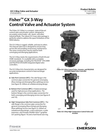
Instruction Manual SupplementDVC6000 SISJune 2009IntroductionFIELDVUE instrumentation provides NO EQUAL diagnostics capabilities that clearly differentiate Fisher controlvalve packages from other control valve packages. However, end-users often do not have a HART orfieldbus-capable control system that enables them to get the benefit of FIELDVUE diagnostic capabilities.There are two easy ways to unleash the power of valve diagnostics in such an environment:Wireless—the THUMr adapter, orHardwiring—using HART to analog convertersThis document provides a hardwiring technical solution, using the Smart HART Loop Interface and Monitor(HIM) from Moore Industries, shown in figure 1, that will enable conventional analog control system users tobenefit from FIELDVUE diagnostic capabilities.Figure 1. Moore Industries HARTr Loop Monitor2
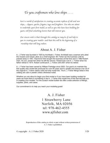
Instruction Manual SupplementDVC6000 SISJune TIONALERTS &ALARMSFIELDVUE PDFIELDVUE ADFigure 2. Four Phases of Valve DiagnosticsUsing the Moore HIM to Convert a HARTR Signal into Analog and DigitalControl SignalsFIELDVUE diagnostics allow you to better manage abnormal situations and/or implement preventivemaintenance on control and safety valves.The practice of valve diagnostics includes four phases:D Fault DetectionD Fault DiscriminationD Process RecoveryD ValidationThe first phase, Fault Detection, is the only phase that requires a FIELDVUE instrument (as the diagnostic tool) tobe capable of automatically reporting the unanticipated or abnormal situation. The other three phases can beperformed by temporarily attaching asset management software to the FIELDVUE instrument.By converting a HART signal into an analog and digital control signal, the Moore HIM can be used to automaticallyreport a FIELDVUE instrument alert on a conventional analog control system.3
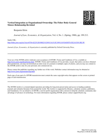
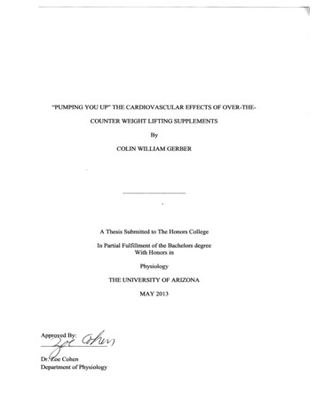
Instruction Manual SupplementDVC6000 SISAIJune 2009ANALOG INPUT: 4-20 mA VALVE TRAVEL READBACKBINARY DIGITAL INPUT: TRAVEL DEVIATIONDIDIBINARY DIGITAL INPUT: DIAGNOSTIC AVAILABLE FOR DOWNLOADAO100%4-20 mA HARTHIMDCSPORT ASUPPLY PRESSURESPORT BFigure 3. Using the HIM in a Conventional Analog Control SystemExample: Control ValveIn this example, shown in figure 3, the HIM is used to automatically report on a conventional analog controlsystem:D the real valve travel is 4-20 mA analog inputD Travel Deviation alert is a binary digital input, andD Diagnostic Data is available as a binary digital inputWhen the valve deviates from the set parameters, an alert is reported in the conventional system, allowing theoperator to trigger a point-to-point diagnostic on the valve (second phase of the valve diagnostic practice: FaultDiscrimination). In this same way, the Diagnostic Data Available alert indicates to the operator that the valve hasdeviated from the set parameters and that this data is available for download to facilitate the Fault Discriminationphase.4
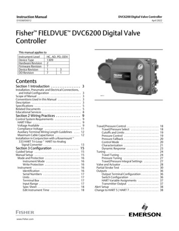
Instruction Manual SupplementDVC6000 SISJune 2009DIBINARY DIGITAL INPUT: VALVE STUCK ALERTBINARY DIGITAL INPUT: PST DIAGNOSTIC IN PROGRESSDIDOS24 VOLTS100%24 VOLTS HARTDIPLCSSHIMPORT ASUPPLY PRESSURESPORT BVALVE OPEN LIMIT SWITCHFigure 4. Using the HIM in a Safety Control SystemExample: Safety ValveThe DVC6000 SIS digital valve controller can be used in conjunction with the HIM to provide additional diagnosticcoverage. Installed transparently across the 4-20 mA or 24 volt instrument loop, the HIM receives the HARTdigital process data and converts the digital information into up to three scalable, isolated analog (4-20 mA)process signals and two relay outputs that are readily accepted by an existing safety or control system, such asthe DCS or PLC.The HIM can be used to hardwire to a PLC (through its two relay outputs) the following DVC6000 SIS alerts:D Valve Stuck, andD Diagnostic in Progress (PST in Progress)The Moore HIM can also be used to automatically report the safety valve position. In some instances, this mayeliminate the need for external limit switches.Additionally, as shown in figure 4, the HIM can also be used to disable an open external limit switch on a safetyvalve during a Partial Stroke Test sequence.NoteNeither Emerson, Emerson Process Management, nor any of their affiliated entities assumesresponsibility for the selection, use, and maintenance of any product. Responsibility for theselection, use, or maintenance of any product remains with the purchaser and end-user.5
Instruction Manual SupplementDVC6000 SISJune 2009FIELDVUE, Fisher, and THUM are marks owned by one of the companies in the Emerson Process Management business division of EmersonElectric Co. Emerson Process Management, Emerson, and the Emerson logo are trademarks and service marks of Emerson Electric Co. HART isa mark owned by the HART Communication Foundation. All other marks are the property of their respective owners.The contents of this publication are presented for informational purposes only, and while every effort has been made to ensure their accuracy, they arenot to be construed as warranties or guarantees, express or implied, regarding the products or services described herein or their use or applicability.All sales are governed by our terms and conditions, which are available upon request. We reserve the right to modify or improve the designs orspecifications of such products at any time without notice. Neither Emerson, Emerson Process Management, nor any of their affiliated entities assumesresponsibility for the selection, use or maintenance of any product. Responsibility for proper selection, use, and maintenance of any product remainssolely with the purchaser and end-user.Emerson Process ManagementMarshalltown, Iowa 50158 USASorocaba, 18087 BrazilChatham, Kent ME4 4QZ UKDubai, United Arab EmiratesSingapore 128461 Singaporewww.Fisher.com6EFisherControls International LLC 2009; All Rights Reserved
Using the HIM in a Conventional Analog Control System Example: Control Valve In this example, shown in figure 3, the HIM is used to automatically report on a conventional analog control system: the real valve travel is 4-20 mA analog input Travel Deviation alert is a binary digital input, and Diagnostic Data is available as a binary digital input