Transcription
CONTROLVALVESOURCEBOOKOIL&GAS
2013 Fisher Controls International LLC. All rights reserved.Fisher, Cavitrol, Control‐Disk, easy‐e, easy‐Drive, ENVIRO‐SEAL, FIELDVUE, High‐Seal, NotchFlo, WhisperFlo, Whisper Trim, andVee‐Ball are marks owned by one of the companies in the Emerson Process Management business unit of Emerson Electric Co.Emerson Process Management, Emerson, and the Emerson logo are trademarks and service marks of Emerson Electric Co. All othermarks are the property of their respective owners. The contents of this publication are presented for informational purposes only, andwhile every effort has been made to ensure their accuracy they are not to be construed as warranties or guarantees, express orimplied, regarding the products or services described herein or their use or applicability. All sales are governed by our terms andconditions, which are available upon request. We reserve the right to modify or improve the designs or specifications of such productsat any time without notice. Neither Emerson, Emerson Process Management, nor any of their affiliated entities assumes responsibilityfor the selection, use, or maintenance of any product. Responsibility for proper selection, use, and maintenance of any product remainssolely with the purchaser and end user.This publication may not be reproduced, stored in a retrieval system, or transmitted in whole or in part, in any form or by any means,electronic, mechanical, photocopying, recording or otherwise, without the written permission of Fisher Controls International LLC.Printed in U.S.A.
Table of ContentsPreface: Oil and Gas Value StreamSection 1: Control Valve Sizing and SelectionChapter 1: Control Valve SelectionChapter 2: Actuator SelectionChapter 3: Liquid Valve SizingChapter 4: Gas Valve SizingChapter 5: Control Valve NoiseChapter 6: Control Valve Cavitation and FlashingSection 2: Oil and Gas Control Valve ApplicationsChapter 7: Onshore Oil and Gas ProductionChapter 8: Offshore Oil and Gas ProductionChapter 9: Natural Gas TreatmentChapter 10: FractionationChapter 11: Oil and Gas TransportationChapter 12: Natural Gas StorageChapter 13: LNG LiquefactionChapter 14: LNG Receiving Terminals
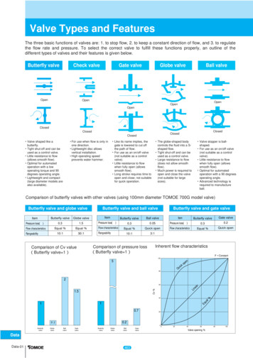
PrefaceThis Oil and Gas Control Valve Sourcebook is intended to be a resource to aid in the understanding of control valve applications for the oil and gasindustry. Under no circumstances should this information alone be used to select a control valve.All valve considerations should be reviewed withyour Fisher sales office or representative as partof any valve selection or specification activity.Section I of this book covers control valve sizingWELLHEADand selection basics. If not familiar with controlvalve terminology it is recommended that this section be reviewed before moving on to Section II.Section II covers the basics of oil and gas production and transportation processes with a focus oncommon control valve applications. Below is ageneral flow diagram of the major topics coveredwithin this section in this edition, and where they fitwithin the oil and gas value chain:FLUIDOIL, GAS, & ACTIONATIONEND USEGASLIQUEFACTIONGASSTORAGEEND USELNGTRANSPORTATIONLNGRECEIVINGWATERINJECTIONOR DISPOSALCHAPTERS7, 8, & 9CHAPTER10CHAPTER11CHAPTERS12 & 13CHAPTER14E1542Oil and Gas Value Chainwww.Fisher.comOILNGLGAS
Section II starts where all oil and gas starts, thewellhead. For any given well a combination of oil,water, and natural gas is produced among otherminor constituents. After production the fluid needsto be processed in order to meet customer specifications. The first process is the separation ofthe components. Descriptions of separation processes in onshore and offshore production facilities can be found in Chapters 7 and 8. Not coveredin this edition are secondary and tertiary production processes, including heavy oil and bitumenproduction. Look for this information in a futureedition.After separation, the oil, gas, and water streamsneed further processing before they are ready forsale, disposal, or reinjection into a reservoir.Chapter 9 is dedicated to gas treatment processes, including dehydration and sulfur removal.Brief oil treatment process descriptions can befound in Chapters 7 and 8. After the oil is treated itis transported to a refinery. For details on controlvalves for refining applications please refer to theFisher Refining Control Valve Sourcebook. Notcovered in this edition are water treatment processes. Look for this and more information on oiltreatment in a future edition.After separation, dehydration, and sulfur removal(if needed) natural gas is usually sold as is to anend user. Often, however, higher value natural gasliquids such as ethane, propane, and butane canbe separated out of the natural gas and sold individually. Chapter 11 covers the natural gas fractionation process.After treatment the oil and gas is ready for transportation. Chapter 10 covers traditional onshoretransportation of both oil and gas. Because thereare seasonal fluctuations in demand for naturalgas, natural gas storage is required (Chapter 12).Liquefying natural gas (Chapter 13) is performedto reduce its volume (1/600th) in order to easilytransport it around the globe. Once at its end destination the LNG needs to be re-gasified beforesale to an end user (Chapter 14).The content in this sourcebook is continually awork in progress, with future editions intended toexpand upon, amend, and add to existing content.For further information, or to answer any questions, please contact your local Fisher sales officeor representative.
Section 1:Control Valve Sizingand Selection
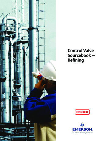
Chapter 1Control Valve SelectionPicking a control valve for a particular applicationused to be straightforward. Usually only one general type of valve was considered, a sliding-stemvalve. Each manufacturer offered a product suitable for the job, and the choice among them depended upon such obvious matters as cost, delivery, vendor relationships and user preference.Today, control valve selection is considerablymore complex, especially for engineers with limited experience or those who have not kept up withchanges in the control valve industry.For many applications, an assortment of slidingstem and rotary valve styles are available. Someare touted as “universal” valves for almost any sizeand service, while others are claimed to be optimum solutions for narrowly defined needs. Eventhe most knowledgeable user may wonder whether they are really getting the most for their moneyin the control valves they have been specifying.Like most decisions, selection of a control valveinvolves a great number of variables. Presentedhere is an overview of the selection process. Thediscussion includes categorization of availablevalve types and a set of criteria to be considered inthe selection process.General Categories ofControl Valves“Control valve” in this discussion means any power-operated valve, whether used for throttling orfor on-off control. Other valve varieties such asmotorized gate valves, louvers, pinch valves andself-operated regulators are not considered here.www.Fisher.comW8119-2Figure 1-1. Modern control valve combinesactuator, valve assembly and digital valvecontroller to provide maximum performance in awide variety of control applications.The major valve types, sliding-stem and rotary, arefurther divided within Table 1-2 into a total of ninesubcategories according to relative performanceand cost. Despite variations found within eachcategory, such as cage-guiding versus stem-guiding, all valves within a given subcategory may beconsidered very much alike in the early stages ofthe selection process.Selecting a valve involves narrowing down to oneof these nine subcategories and then comparingspecific valves in that group.
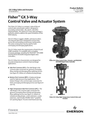
TFE V-RINGBONNET GASKETSPIRALWOUNDGASKETBACKUP RINGSEAL RINGCAGEGASKETVALVE PLUGGROOVEPINSEAT RINGGASKETMETALDISK SEATPTFE DISKMETAL DISKRETAINERW0992-4Figure 1-2. Standard globe sliding-stem valve design is typified by the ET. A broad range of sizes, materials and endconnections is available. The balanced plug reduces plug force and allows use of smaller actuators. These valves arethe first choice for applications less than NPS 3 size.X0215-1Figure 1-3. Severe service capability in globe valves demonstrated by this Large ET. The drilled hole cage providesattenuation of flow noise by splitting the flow into multiple passages. Spacing of the holes is carefully controlled toeliminate jet interaction and higher resultant noise levels.1 2
Sliding-Stem ValvesThe most versatile of control valves are the slidingstem designs. Globe, angle, and Y-pattern valvescan be purchased in sizes ranging from NPS 1/2 36. More choices of materials, end connectionsand control characteristics are included here thanin any other product family.Globe valves are available in cage-guided, postguided and stem-guided designs, with flanged,screwed or weld ends. Economical cast iron aswell as carbon steel, stainless steel and otherhigh-performance body materials are available.Available valve body pressure ratings range toASME CL4500 or API 10,000.The globe valve’s precise throttling capabilities,overall performance and general sturdiness makethem a bargain despite their slight cost premium.With the globe valve, the buyer gets a rugged, dependable unit intended for long, trouble-free service.W3379Figure 1-4. EHD is typical of high-pressure globevalves. Rated at ASME CL2500, it provides throttling control of high-pressure steam and fluids.Anti-noise and anti-cavitation trims are availableto handle flow problems.Sliding-stem valves are ruggedly built to handlefield conditions such as piping stress, vibration,and temperature changes. In sizes through NPS 3- 4, incremental costs over rotary valves are low incontrast to the increments in benefits received.For many extreme service conditions, sliding-stemvalves are the only suitable choice. These situations include high pressures and temperatures,excessive noise, and the potential for cavitation.Due to process demands, these applications require the rugged construction of the sliding-stemdesign.Barstock valves are small, economical slidingstem valves featuring bodies machined from barstock. Body sizes range from fractions of NPS 1 3; flow capacities generally are lower than those ofgeneral purpose valves. End connections usuallyare flangeless (for mounting between pipingflanges) or screwed.The main advantage of the barstock valve is thatfar more materials are readily available in bar formthan in cast form. Consequently, these valves areoften used where there are special corrosion considerations.Also, the compactness and general high-qualityconstruction of barstock valves make them attractive for low flow rate applications. Overall, they arean economical choice when they can be used.X0184Figure 1-5. NPS 1 Baumann 24000 Little Scottyvalve with a size 32 actuator anda FIELDVUE DVC6200The third subcategory, which involves the lowestcost products among sliding-stem valves, utilizes“economy” bodies (Figure 1-5). These valves areused for low-pressure steam, air and water applications that are not demanding. Sizes availablerange from NPS 1/2 - 4. Body materials includebronze, cast iron, steel and SST. Pressure classesgenerally stop at ASME CL300. Compared to regular sliding-stem valves, these units are very simple; their actuators are smaller, and their construc-1 3
BODY OUTLETVALVE BALLOUTLETVALVE BODYTHRUSTWASHERMAIN SHAFTBEARINGSEALCARRIERDRIVE SHAFTO-RINGFOLLOWER SHAFTW7169SEAL PROTECTORRING OR FLOW RINGVALVE BALLINLET SEALSHIM SEALSFigure 1-6. High-pressure ball valves feature heavy shafts and full ball designs. This V250 is suitable forpressure drops to 2220 psig. ASME CL600 and CL900 bodies are available—sizes range to NPS 24.W7435Figure 1-7. Applications to ASME CL600 can be handled by the V150/V200/V300 Vee-Ballt.This product incorporates many features to improve throttling performance and rangeability. Tight shutoff isachieved by using either heavy-duty metal seals or composition seals.tion is economical. Severe service trims for noiseand cavitation service are not available in theseproducts.Ball ValvesThere are two subcategories of ball valves. Thethrough-bore or full-ball type illustrated in Figure1-6 is used typically for high pressure drop throttling and on-off applications in sizes to NPS 24.Full port designs exhibit high flow capacity and lowsusceptibility to wear by erosive streams. However, sluggish flow response in the first 20% of balltravel may make full-bore ball valves unsuitable forsome throttling applications.1 4Another popular kind of ball valve is the segmented-ball style (Figure 1-7). This subcategoryutilizes a reduced bore, and the edge of the ballsegment has a contoured notch shape for betterthrottling control and higher rangeability. Intendedprimarily for modulating service, segmented-ballvalves are generally higher in overall control performance than full-ball products.Segmented-ball valves with their splined shaft connections are engineered to eliminate lost motion,which is detrimental to performance. The use ofheavy-duty metal and fluoroplastic sealing elements allows wide temperature and fluid applicability. Their straight-through flow design achieveshigh capacity with sizes ranging through NPS 24and pressure ratings to ASME CL600. Price isgenerally lower than that of globe valves.
RETAINERVALVE PLUGFACE SEALSSEAT RINGPACKINGBEARINGVALVE SHAFTBEARING STOPTAPER ANDEXPANSION PINSTHRUST WASHERVALVE BODYW4170-3 / ILFigure 1-8. The V500 eccentric plug valve is specially designed for severe rotary applications. Since the valve plug“cams” into the seat ring upon closure, it features tight shutoff with globe valve style seating. It also offers excellentresistance to abrasive wear and flashing induced erosion.Eccentric Plug ValvesThis class of valves combines many features ofsliding-stem and rotary products. Eccentric plugvalves feature rotary actuation. But, unlike mostrotary valves, this product utilizes a massive, rigidseat design.Eccentric-plug valves (Figure 1-8) exhibit excellentthrottling capability and resistance to erosion.Thus, many of the good aspects of both rotary andsliding-stem designs are combined.Sizes generally range through NPS 8; pressureratings go to ASME CL600. Both flanged andflangeless body styles are available in a variety ofmaterials.The requirement for zero or low leakage gave riseto new designs such as the lined and high performance butterfly valves (BFV’s).Lined butterfly valves feature an elastomer or fluoropolymer (TFE) lining that contacts the disk toprovide tight shutoff. Since this valve design depends on interference between the disc and linerfor shutoff, it is more limited in pressure drop.Temperature ranges typically are limited due to theelastomer disk seal.In addition to serving as the disk seal, the lineralso protects the inner bore of the valve body fromthe process fluid, which allows these valves to beused in many corrosive situations. Elastomer-linedBFV’s are generally the lowest price productsavailable as control valves in medium to largesizes.Heavy shafts and discs, full-rated bodies and sophisticated seals that allow tight shutoff againsthigh pressures characterize high performance but-1 5
SPRINGW6235-2 / ILTAPER PINSAND HOLLOWPINSSEALRINGVALVE BODYDISKBEARINGPACKING FOLLOWERPTFE V-RINGPACKINGSPLINED SHAFTFigure 1-9. High performance butterfly valves provide excellent performance and value. High-pressure capability, tightshutoff and excellent control are featured as standard. This 8560 design is made for ASME CL150 applications.terfly valves such as the one in Figure 1-9. Thesevalves provide an excellent combination of performance features, lightweight and very reasonablepricing.In offset disc designs, eccentric shaft mountingallows the valve disc to swing clear of its seal tominimize wear and torque. The offset disc allowsuninterrupted sealing and a seal ring that can bereplaced without removing the disc. High performance butterfly valves come in sizes from NPS 2through NPS 72, with flangeless, lugged, doubleflanged connections, carbon steel or stainlesssteel bodies, and pressure ratings to ASMECL2500. Tight metal-to-metal seals, made possible with advanced eccentric design, provide tightshutoff in applications that are too hot for elastomer lined valves. Considering this tight shutoffcapability and heavy-duty construction, high performance butterfly valves can be a suitable optionto many applications where sliding-stem valvesare normally specified.Classes 150, 300 and 600. (Source documentsare ASME/ANSI Standards B16.34, “Steel Valves,”and ANSI/ASME B16.1, “Cast Iron Pipe Flangesand Flanged Fittings.”) For a given body material,each ASME Class corresponds to a prescribedprofile of maximum pressures that decrease withtemperature according to the strength of the material. Each material also has a minimum and maximum service temperature based on loss of ductilityor loss of strength. For most applications, the required pressure rating is dictated by the application. However, since all products are not availablefor all ASME Classes, it is an important consideration for selection.Table 1-1. Suggested General Criteria for Selecting Typeand Brand of Control ValveBody pressure ratingHigh and low temperature limitsMaterial compatibility and durabilityInherent flow characteristic and rangeabilityMaximum pressure drop (shutoff and flowing)Noise and cavitationEnd connectionsGeneral Selection CriteriaShutoff leakageMost of the considerations that guide the selectionof valve type and brand are rather basic. However,there are some matters that may be overlooked byusers whose familiarity is mainly limited to just oneor a few valve types. Table 1-1 below provides achecklist of important criteria; each is discussed atlength following the table.Nature of flowing mediaPressure RatingsBody pressure ratings ordinarily are consideredaccording to ASME pressure classes—the mostcommon ones for steel and stainless steel being1 6Capacity versus costDynamic performanceTemperature ConsiderationsRequired temperature capabilities are also a foregone conclusion, but one that is likely to narrowvalve selection possibilities. The considerationsinclude the strength or ductility of the body material as well as relative thermal expansion of variousparts.Temperature limits also may be imposed due todisintegration of soft parts at high temperatures or
Temperature affects valve selection by excludingcertain valves that do not have high- or low-temperature options. It also may have some effect onthe valve’s performance. For instance, going fromPTFE to metal seals for high temperatures generally increases the shutoff leakage flow. Similarly,high temperature metal bearing sleeves in rotaryvalves impose more friction on the shaft than doPTFE bearings, so that the shaft cannot withstandas high a pressure-drop load at shutoff. Selectionof valve packing is also based largely on servicetemperature.Material SelectionThe third criterion in Table 1-1, material compatibility and durability, is a more complex consideration. At issue may be corrosion by the processfluid, erosion by abrasive material, flashing, cavitation or simply a matter of process pressure andtemperature. The piping material usually indicatesthe body material. However, since velocity is higher in valves other factors must be considered.When these items are included, often valve andpiping materials will differ. The trim materials, inturn, are usually a function of the body material,temperature range and qualities of the fluid.Flow CharacteristicThe next selection criterion, inherent flow characteristic, refers to the pattern in which the flow atconstant pressure drop changes according tovalve position.Typical characteristics are quick-opening, linearand equal-percentage. The choice of characteristicmay have a strong influence on the stability orcontrollability of the process (see Table 1-3), sinceit represents the change of valve gain relative totravel.Most control valves are carefully ”characterized”by means of contours on a plug, cage, or ball ele-100QUICKOPENING80PERCENT OF MAXIMUM FLOWloss of resiliency at low temperatures. The softmaterials under consideration include various elastomers, plastics, and PTFE. They may be found inparts such as seat rings, seal or piston rings, packing, rotary shaft bearings and butterfly valve liners.Typical upper temperature limits for elastomersare in the 200-350 F (93-176 C) range, and thegeneral limit for PTFE is 450 F (232 CENT OF RATED TRAVELFigure 1-10. Many control valves offer a choiceof characteristic. Selection to match processrequirements is guided by simple rules.Adherence to these guidelines will help assurestable operation.ment. Some valves are available in a variety ofcharacteristics to suit the application, while othersoffer little or no choice. To quantitatively determinethe best flow characteristic for a given application,a dynamic analysis of the control loop can be performed.The accompanying drawing illustrates typical flowcharacteristic curves (Figure 1-10). The quickopening flow characteristic provides for maximumchange in flow rate at low valve travels with a fairlylinear relationship. Additional increases in valvetravel give sharply reduced changes in flow rate,and when the valve plug nears the wide open position, the change in flow rate approaches zero. In acontrol valve, the quick opening valve plug is usedprimarily for on-off service.The linear flow characteristic curve shows that theflow rate is directly proportional to the valve travel.This proportional relationship produces a characteristic with a constant slope so that, with constantpressure drop, the valve gain will be the same atall flows. The linear valve plug is commonly specified for liquid level control and for certain flow control applications requiring constant gain.In the equal percentage flow characteristic, equalincrements of valve travel produce equal percentage changes in the existing flow. The change inflow rate is always proportional to the flow rate justbefore the change in valve plug, disc, or ball position is made. When the valve plug, disc, or ball isnear its seat and the flow is small, the change in1 7
flow rate will be small; with a large flow, thechange in flow rate will be large.An equal percentage flow characteristic is usedgenerally on pressure control applications and onother applications where a large percentage of thepressure drop is normally absorbed by the systemitself with only a relatively small percentage available at the control valve. Valves with an equal percentage characteristic should also be consideredwhere highly varying pressure drop conditionscould be expected.RangeabilityAnother aspect of a valve’s flow characteristic is itsrangeability, which is the ratio of its maximum andminimum controllable flow rates. Exceptionallywide rangeability may be required for certain applications to handle wide load swings or a combination of start-up, normal and maximum workingconditions. Generally speaking, rotary valves—especially partial ball valves—have greater rangeability than sliding-stem varieties.Use of PositionersA positioner is an instrument that helps improvecontrol by accurately positioning a control valveactuator in response to a control signal. They areuseful in many applications and are required withcertain actuator styles in order to match actuatorand instrument pressure signals or to provide operating stability. To a certain extent, a valve withone inherent flow characteristic can also be madeto perform as though it had a different characteristic by using a nonlinear (i.e., characterized) positioner-actuator combination. The limitation of thisapproach lies in the positioner’s frequency response and phase lag compared to the characteristic frequency of the process.Although it is common practice to use a positioneron every valve application, each application shouldbe reviewed carefully.Pressure DropThe maximum pressure drop a valve can tolerateat shutoff or when partially or fully open is an important selection criteria. Sliding-stem valves aregenerally superior in both regards because of the1 8rugged nature of their moving parts. Many rotaryvalves are limited to pressure drops well below thebody pressure rating, especially under flowing conditions, due to dynamic stresses that high velocityflow imposes on the disk or ball segment.Noise and CavitationNoise and cavitation are two considerations thatoften are grouped together because both may result from high pressure drops and large flow rates.They are treated by special modifications to standard valves. Chapter 5 discusses noise generation and abatement, while Chapter 6 discusses thecavitation phenomenon and its impact and treatment.End ConnectionsThe three common methods of installing controlvalves in pipelines are by means of screwed pipethreads, bolted flanges, and welded end connections. At some point in the selection process, thevalve’s end connections must be considered withthe question simply being whether the desiredconnection style is available in the valve beingconsidered. Maintenance, weight, size, and service conditions all contribute to what end connection is used.In some situations, this matter can limit the selection rather narrowly. For instance, if a piping specification calls for welded connections only, thechoice usually is limited to sliding-stem valves.Screwed end connections, popular in small controlvalves, offer more economy than flanged ends.The threads usually specified are tapered femaleNPT (National Pipe Thread) on the valve body.They form a metal-to-metal seal by wedging overthe mating male threads on the pipeline ends.This connection style is usually limited to valvesnot larger than NPS 2, and is not recommendedfor elevated temperature service.Valve maintenance might be complicated byscrewed end connections if it is necessary to takethe body out of the pipeline. Screwed connectionsrequire breaking a flanged joint or union connection to permit unscrewing the valve body from thepipeline.Flanged end valves are easily removed from thepiping and are suitable for use through the range
ends come in two styles, socket weld and buttweld.Shutoff CapabilityFLAT‐FACERAISED‐FACERING‐TYPE JOINTA7098Figure 1-11. Popular varieties of bolted flangeend connections.Some consideration must be given to a valve’sshutoff capability, which usually is rated in terms ofClasses specified in ANSI/FCI70-2 (Table 1-4). Inservice, shutoff leakage depends on many factors,including but not limited to, pressure drop, temperature, the condition of the sealing surfaces, andactuator force.Since shutoff ratings are based on standard testconditions that can be very different from serviceconditions, service leakage cannot be predictedaccurately. However, the shutoff Class provides agood basis for comparison among valves of similarconfiguration. It is not uncommon for valve usersto overestimate the shutoff class required.Since tight shutoff valves generally cost more bothin initial cost as well as in later maintenance expense, serious consideration is warranted. Tightshutoff is particularly important in high-pressurevalves, considering that leakage in these applications can lead to the ultimate destruction of thetrim. Special precautions in seat material selection,seat preparation and seat load are necessary toensure success.SOCKET WELDING ENDSFlow CapacityA7099BUTT WELDING ENDSFigure 1-12. Common welded end connections.of working pressures that most control valves aremanufactured (Figure 1-11).Flanged end connections can be used in a temperature range from absolute zero ( 273 F) toapproximately 1500 F (815 C). They are used onall valve sizes. The most common flanged endconnections include flat face, raised face, and ringtype joint.Welded ends on control valves are leak tight at allpressures and temperatures and are economicalin initial cost (Figure 1-12). Welded end valves aremore difficult to remove from the line and are obviously limited to weldable materials. WeldedFinally, the criterion of capacity or size can be anoverriding constraint on selection. For very largelines, sliding-stem valves are more expensive thanrotary types. On the other hand, for very smallflows, a suitable rotary valve may not be available.If future plans call for significantly larger flow, thena sliding-stem valve with replaceable restrictedtrim may be the answer. The trim can be changedto full size trim to accommodate higher flow ratesat less cost than replacing the entire valve bodyassembly.Rotary style products generally have much highermaximum capacity than sliding-stem valves for agiven body size. This fact makes rotary productsattractive in applications where the pressure dropavailable is rather small. However, it is of little orno advantage in high-pressure drop applicationssuch as pressure regulation or letdown.ConclusionWe may simplify the process of selection as follows:1 9
For most general applications, it makes senseboth economically as well as technically to usesliding-stem valves for lower flow ranges, ballvalves for intermediate capacities, and high performance butterfly valves for the very largest requiredflows.For sizes less than NPS 3, general-purpose sliding-stem valves provide an exceptional value. Fora minimal price premium over rotary products, theyoffer unparalleled performance, flexibility and service life. In NPS 3 size and larger, the premium forthese devices over rotary products is warranted.For severe service applications the most frequently used and often the only available product is thesliding-stem valve.Applications ranging from NPS 4 to NPS 6 arebest served by such transitional valve styles as thee
ing of control valve applications for the oil and gas industry. Under no circumstances should this in-formation alone be used to select a control valve. All valve considerations should be reviewed with your Fisher sales office or representative as part of any valve selection or specification activity. Section I of this