Transcription
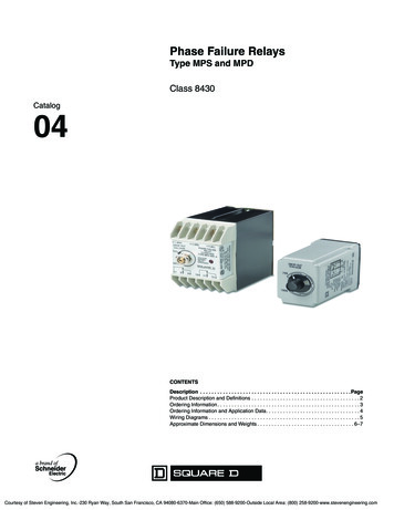
Phase Failure RelaysType MPS and MPDClass 8430Catalog04CONTENTSDescription . . . . . . . . . . . . . . . . . . . . . . . . . . . . . . . . . . . . . . . . . . . . . . . . . . . . .PageProduct Description and Definitions . . . . . . . . . . . . . . . . . . . . . . . . . . . . . . . . . . . . . . 2Ordering Information. . . . . . . . . . . . . . . . . . . . . . . . . . . . . . . . . . . . . . . . . . . . . . . . . . 3Ordering Information and Application Data. . . . . . . . . . . . . . . . . . . . . . . . . . . . . . . . . 4Wiring Diagrams . . . . . . . . . . . . . . . . . . . . . . . . . . . . . . . . . . . . . . . . . . . . . . . . . . . . . 5Approximate Dimensions and Weights . . . . . . . . . . . . . . . . . . . . . . . . . . . . . . . . . . 6–7Courtesy of Steven Engineering, Inc.-230 Ryan Way, South San Francisco, CA 94080-6370-Main Office: (650) 588-9200-Outside Local Area: (800) 258-9200-www.stevenengineering.com
Phase Failure Relays Types MPS and MPDClass 8430 – Product Description and DefinitionsThree-Phase MonitoringIf, for any reason, the motor windings draw morecurrent than they are rated for, excess heat isgenerated, causing deterioration of the motorinsulation. This deterioration is irreversible andcumulative. Eventually, the windings will short to themotor housing, causing motor failure. The reactiontime of thermal overload units may be too slow toprovide effective protection from the excess heatgenerated by high current. A phase failure relay, bylimiting the overcurrent will help to:from the excessive heat generated in the motorwindings when a phase failure occurs. Increase motor life Reduce the very costly repair or replacement ofmotors Minimize downtime due to motor problems Reduce the risk of electric shock or fire due to theshorting out of motor windingsProtecting a three-phase motor against phasefailure is difficult because a lightly loaded threephase motor operating only on single phase willgenerate a voltage, often called regenerated voltageor back EMF, in its open winding almost equal to thelost voltage. Therefore, voltage sensing deviceswhich monitor only the voltage magnitude may notprovide complete protection from a phase failurewhich occurs when the motor is running. A greaterdegree of protection can be obtained from a devicewhich can detect the phase angle displacementaccompanying a phase failure. Under normalconditions, the three-phase voltages are 120degrees out of phase with respect to one another. Aphase failure will cause a phase angle displacementaway from the normal 120 degrees.Types of Protective RelaysPhase Reversal DetectionThere are two major types of protective relays forthree-phase systems: current sensing and voltagesensing. The advantages of current sensingprotective relays over voltage sensing relays are thatthey are not fooled by back EMF (ElectromotiveForce) which accompanies a phase failure on motorloads and they also can detect an abnormalcondition on either the line side or load side in abranch circuit in which the relay is used. Voltagesensing devices can only detect abnormalconditions on the line side of where the relay isconnected.Phase reversal can occur when maintenance isperformed on motor-driven machinery, whenmodifications are made to the power distributionsystem, or when power restoration results in adifferent phase sequence than before the poweroutage. Phase reversal detection is important if amotor running in reverse may damage the drivenmachinery or injure personnel. The National ElectricCode (NEC) requires phase reversal protection onall equipment transporting people, such asescalators or elevators.However, a voltage sensing relay has an importantadvantage in that it can detect an abnormalcondition independent of the motor’s running status.A current sensing device requires the motor to berunning before an abnormal condition can bedetected. Therefore, a voltage sensing device willprovide pre-start protection while a current sensingdevice will not. Other advantages of voltage sensingdevices are that they are easy to install, aregenerally less expensive because they do not needcurrent transformers, and require only voltageconnections so that they may be appliedindependent of the system load.Phase Failure DetectionA phase failure may occur because of a blown fusein some part of the power distribution system, amechanical failure within the switching equipment,or if one of the power lines open. A three-phasemotor running on single phase draws all of itscurrent from the remaining two lines. Attempting tostart a three-phase motor on single phase will causethe motor to draw locked-rotor current and the motorwill not start. The reaction time of thermal overloadunits may be too slow to provide effective protectionVoltage Unbalance DetectionVoltage unbalance can occur when incoming linevoltages delivered by the power company are ofdifferent levels, or when single-phase loads such aslighting, electrical outlets and single-phase motorsare connected on individual phases and notdistributed in a balanced way. In either case, acurrent unbalance will result on the system whichshortens motor life and diminishes motor efficiency.An unbalanced voltage applied to a three-phasemotor can result in a current unbalance in the motorwindings equal to several times the voltageunbalance. This will increase the heat generated, amajor cause of rapid deterioration of motorinsulation.UndervoltageUndervoltage may occur if the power supplied by thelocal power company is overloaded, causing thevoltage to drop, which is known as a brown out. Anundervoltage condition can also occur in remoteareas at the end of long power lines. As the voltageavailable to the motor is decreased, the currentdrawn by the motor increases, resulting in generatedheat which deteriorates the motor insulation.2 1998–2004 Schneider Electric All Rights Reserved6/2004Courtesy of Steven Engineering, Inc.-230 Ryan Way, South San Francisco, CA 94080-6370-Main Office: (650) 588-9200-Outside Local Area: (800) 258-9200-www.stevenengineering.com
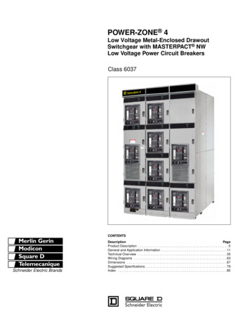
Phase Failure Relays Type MPS and MPDOrdering Information – Class 84308430MPS8430MPD Socket mountedUndervoltage adjustment from 75 to 100%Detects phase unbalances over 10%Hard output contacts with 240 Vac ratingOffers the same protection as the 8430MPSSurface mountedLED indication when relay is energizedLocking potentiometer undervoltageadjustment Hard output contacts with 600 Vac ratingBoth relays protect motors against: Phase failureVoltage unbalancePhase iptionMonitoredVoltageCatalog NumberRecommendedSocket240 V–60 Hz8430MPSV248501NR51 or8501NR52480 V–60 Hz8430MPSV298501NR82120 V–60 Hz8430MPDV20240 V–60 Hz8430MPDV24480 V–60 Hz8430MPDV29600 V–60 Hz8430MPDV32A socket-mountedvoltage sensingphase failure relaySPDTA surface-mountedvoltage sensingphase failure relayNot requiredDPDTSockets for 8430MPS Relays35mm DIN 3 Track Mount or Direct Panel MountSocket RatingProductDescription8 pin tubular single tierscrew terminal8 pin tubular double tierscrew terminal11 pin spade double tierscrew terminalCatalog NumberULCSA10 A, 600 V15 A, 300 V10 A, 300 V5 A, 600 V16 A, 300 V15 A, 300 V Package 01NR8218501NR82B1010 A, 300 V15 A, 300 V Depending on the application, the RM4 relay should be considered. Rated 10 A, 480 V when used withan 8430MPSV29 phase failure relay.36/2004 1998–2004 Schneider Electric All Rights ReservedCourtesy of Steven Engineering, Inc.-230 Ryan Way, South San Francisco, CA 94080-6370-Main Office: (650) 588-9200-Outside Local Area: (800) 258-9200-www.stevenengineering.com
Phase Failure Relays Type MPS and MPDClass 8430 – Ordering Information, Application Data35 mm DIN 3 Mounting TrackHeightLengthCatalog NumberPackage 109080MH279100.5 m (19.68 in.)1.0 m (39.37 in.)7.5 mm (0.30 in.)2.0 m (78.74 in.)15.0 mm (0.60 in.)9080MH37910AM1DP20010AM1ED20010AM1DE200102.0 m (78.74 in.)For additional track lengths or technical data, refer to the IEC Type Terminal Block Catalog, 9080CT9602.AccessoriesProductDescriptionCatalog NumberPackage QuantityScrew-on end clamp9080MHA1050Screw-on end clampAB1AB8M3550Hold down for8430MPS relays8501NH71Undervoltage Adjustment:Conformity to Standards:75 to 100% of nominal voltage8430MPSPhase Unbalance Detection:File E78351 CCN NLDX with proper socket8430MPSV24 – With 8501NR51 or NR52 socket8430MPSV29 – With 8501NR82 socket Greater than 10%Maximum Power Consumption:File E42240 CCN NLDX without sockets8430MPS–5.0 VA (240 V), 5.5 VA (480 V)8430MPD–5.0 VA (120 V), 5.5 VA (240 V),6.5 VA (480 V), 7 VA (600 V)File 060905 Class 3211 038430MPD Transient Spike Protection:File E78351 CCN NLDX5000 volts for 50 microsecondsFile 060905 Class 3211 038501NRTemperature Rating:Operating: -5 to 50 C (23 to 122 F)Storage: -20 to 70 C (-4 to 158 F)File E66924 CCN SW1V2File LR84913 Class 3211 07Screw Tightening Torque:8430MPD Relay: 7–9 lb-in (0.8–1.0 N m)8501NR51, 52 or 82 sockets: 7–9 lb-in (0.8–1.0 N m)Output Contact Rating:AC ageInductiveWire Range:ResistiveMakeVABreakVAMake 360360360552.52.555558430MPD Relay: One or two #18 to #14 AWG Copperwire (75 C insulation or higher)8501NR Sockets: One or two #12 to #22 AWG Copperwire (75 C insulation or higher)Pick-up Time:Typically 0.1 seconds when correct three-phase voltageis appliedDrop Out Time:Typically 3 seconds for any incorrect voltage condition.4 1998–2004 Schneider Electric All Rights Reserved6/2004Courtesy of Steven Engineering, Inc.-230 Ryan Way, South San Francisco, CA 94080-6370-Main Office: (650) 588-9200-Outside Local Area: (800) 258-9200-www.stevenengineering.com
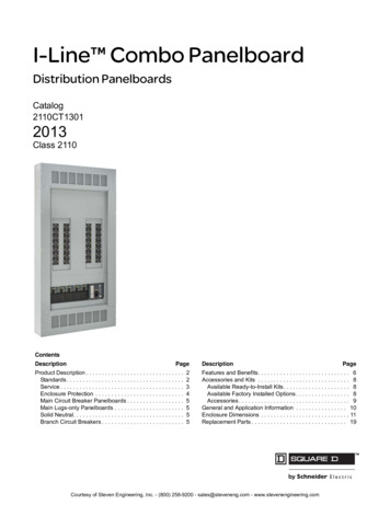
Phase Failure Relays Type MPS and MPDClass 8430 – Wiring Diagrams8430 MPS and MPD relays will resetautomatically when the phase abnormality iscorrected. Therefore, 3-wire control should beused to accomplish safe operation ofequipment.Line Side MonitoringInterfacing Phase Failure Relays With ShuntTrip Circuit BreakersPhase failure relays are often used to control ashunt trip circuit breaker. When this is done, caremust be taken to insure that the shunt trip circuitalways has an adequate source available. Thiscan be accomplished by using the diagram below.With the relay connected before the starter, themotor can be started in the reverse direction.However the motor is unprotected against phasefailures between the relay and the motor.With a Nonreversing PDML1MotorConnection L2L33-PhaseMotorMM8430MPS8430MPDWith a Reversing 3RRRIf a phase failure occurs on L2 or L3, the shunt tripcoil will draw power from L1 through the controlrelay (CR) contacts and phase failure relaycontacts (which will change state upon detectinga phase failure). If a phase failure occurs on L1,the control relay (CR) contacts change state. Theshunt trip coil will now draw power from L2through the CR contacts and phase failure relaycontacts.If the control relay coil or contacts, the phasefailure relay contacts, or the shunt trip coil doesnot have the same voltage rating as the motor,control transformers may be interposed whereneeded.8430MPS8430MPDLoad Side MonitoringWith the relay connected directly to the motor, thetotal feed lines are monitored. This connectionshould not be used with reversing motors.With a Nonreversing DL1MotorConnection L2L3M3-PhaseMotorMM8430MPS8430MPD56/2004 1998–2004 Schneider Electric All Rights ReservedCourtesy of Steven Engineering, Inc.-230 Ryan Way, South San Francisco, CA 94080-6370-Main Office: (650) 588-9200-Outside Local Area: (800) 258-9200-www.stevenengineering.com
Phase Failure Relays Type MPS and MPDApproximate Dimensions and Weights – Class 8430543216ØA7ØB8ØC8430MPSV24Weight: 7.1 oz (0.20 kg)Terminal screws M3 .5 x .77201.30331.6041Top View0.97258501NR51Weight: 1.6 oz (0.05 kg)TerminalscrewsM3.5 x 780.88221.09281.42360.71181.112827Top View8501NR52Weight: 1.6 oz (0.05 kg)Dimensions in.------mm6 1998–2004 Schneider Electric All Rights Reserved6/2004Courtesy of Steven Engineering, Inc.-230 Ryan Way, South San Francisco, CA 94080-6370-Main Office: (650) 588-9200-Outside Local Area: (800) 258-9200-www.stevenengineering.com
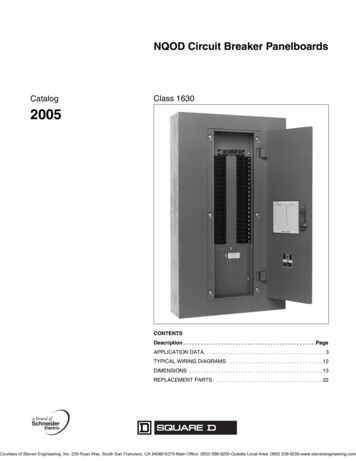
Phase Failure Relays Type MPS and MPDApproximate Dimensions and Weights – Class 8430123456789BAØCØBØA8430 MPSV29Weight: 7.9 oz (0.23 9871.5238.701.5539.311.70343.25Terminal Screws M3.5 x P VIEW8501NR82Weight: 2.3 oz (0.07 kg)ØAØBØC123456789 10 11 128430MPDWeight: 15.9 oz (0.45 kg)Dimensions in.------mm76/2004 1998–2004 Schneider Electric All Rights ReservedCourtesy of Steven Engineering, Inc.-230 Ryan Way, South San Francisco, CA 94080-6370-Main Office: (650) 588-9200-Outside Local Area: (800) 258-9200-www.stevenengineering.com
Schneider Electric USA8001 Highway 64 EastKnightdale, NC omSchneider Electric Canada19 Waterman Avenue,M4B 1 Y2Toronto, log No. 8430CT9701R6/04 June 2004 1998–2004 Schneider Electric All Rights ReservedReplaces 8430CT9701 dated 01/1998.Courtesy of Steven Engineering, Inc.-230 Ryan Way, South San Francisco, CA 94080-6370-Main Office: (650) 588-9200-Outside Local Area: (800) 258-9200-www.stevenengineering.com
Phase Failure Relays Type MPS and MPD -----