Transcription
Cortex -M0 Revision: r0p0Technical Reference ManualCopyright 2009 ARM Limited. All rights reserved.ARM DDI 0432C (ID113009)
Cortex-M0Technical Reference ManualCopyright 2009 ARM Limited. All rights reserved.Release InformationThe following changes have been made to this book.Change historyDateIssueConfidentialityChange19 March 2009ANon-Confidential, Restricted AccessFirst release for r0p027 July 2009BNon-Confidential, Restricted AccessSecond release for r0p030 November 2009CNon-ConfidentialThird release for r0p0Proprietary NoticeWords and logos marked with or are registered trademarks or trademarks of ARM Limited in the EU andother countries, except as otherwise stated below in this proprietary notice. Other brands and namesmentioned herein may be the trademarks of their respective owners.Neither the whole nor any part of the information contained in, or the product described in, this documentmay be adapted or reproduced in any material form except with the prior written permission of the copyrightholder.The product described in this document is subject to continuous developments and improvements. Allparticulars of the product and its use contained in this document are given by ARM Limited in good faith.However, all warranties implied or expressed, including but not limited to implied warranties ofmerchantability, or fitness for purpose, are excluded.This document is intended only to assist the reader in the use of the product. ARM Limited shall not be liablefor any loss or damage arising from the use of any information in this document, or any error or omission insuch information, or any incorrect use of the product.Where the term ARM is used it means “ARM or any of its subsidiaries as appropriate”.Confidentiality StatusThis document is Non-Confidential. The right to use, copy and disclose this document may be subject tolicense restrictions in accordance with the terms of the agreement entered into by ARM and the party thatARM delivered this document to.Unrestricted Access is an ARM internal classification.Product StatusThe information in this document is final, that is for a developed product.iiCopyright 2009 ARM Limited. All rights reserved.Non-Confidential, Unrestricted AccessARM DDI 0432CID113009
Web Addresshttp://www.arm.comARM DDI 0432CID113009Copyright 2009 ARM Limited. All rights reserved.Non-Confidential, Unrestricted Accessiii
ivCopyright 2009 ARM Limited. All rights reserved.Non-Confidential, Unrestricted AccessARM DDI 0432CID113009
ContentsCortex-M0 Technical Reference ManualPrefaceAbout this book . xiiFeedback . xvChapter 1Introduction1.11.21.31.41.51.6Chapter 2About the functions . 2-2Interfaces . 2-4Programmers Model3.13.23.33.43.5ARM DDI 0432CID1130091-21-31-41-51-61-9Functional Description2.12.2Chapter 3About the processor .Features .Interfaces .Configurable options .Product documentation, design flow and architecture .Product revisions .About the programmers model . 3-2Modes of operation and execution . 3-3Instruction set summary . 3-4Memory model . 3-9Processor core registers summary . 3-11Copyright 2009 ARM Limited. All rights reserved.Non-Confidential, Unrestricted Accessv
Contents3.6Chapter 4Exceptions . 3-12System Control4.14.2Chapter 5About system control . 4-2System control register summary . 4-3Nested Vectored Interrupt Controller5.15.2Chapter 6Debug6.16.2Appendix AAbout the NVIC . 5-2NVIC register summary . 5-3About debug . 6-2Debug register summary . 6-9RevisionsGlossaryviCopyright 2009 ARM Limited. All rights reserved.Non-Confidential, Unrestricted AccessARM DDI 0432CID113009
List of TablesCortex-M0 Technical Reference ManualTable 1-1Table 3-1Table 3-2Table 3-3Table 4-1Table 4-2Table 5-1Table 6-1Table 6-2Table 6-3Table 6-4Table 6-5Table 6-6Table 6-7Table 6-8Table A-1Table A-2Table A-3ARM DDI 0432CID113009Change history . iiProcessor configurable options . 1-5Cortex-M0 instruction summary . 3-4Memory map usage . 3-9Processor core register set summary . 3-11System control registers . 4-3CPUID bit register assignments . 4-4NVIC registers . 5-3Cortex-M0 ROM table identification values . 6-4Cortex-M0 ROM table components . 6-4SCS identification values . 6-5DWT identification values . 6-6BPU identification registers . 6-7Debug registers summary . 6-9BPU register summary . 6-9DWT register summary . 6-9Issue A . A-1Differences between issue A and issue B . A-1Differences between issue B and issue C . A-2Copyright 2009 ARM Limited. All rights reserved.Non-Confidential, Unrestricted Accessvii
List of TablesviiiCopyright 2009 ARM Limited. All rights reserved.Non-Confidential, Unrestricted AccessARM DDI 0432CID113009
List of FiguresCortex-M0 Technical Reference ManualFigure 2-1Figure 4-1Figure 6-1ARM DDI 0432CID113009Functional block diagram . 2-2CPUID bit register assignments . 4-4CoreSight discovery . 6-3Copyright 2009 ARM Limited. All rights reserved.Non-Confidential, Unrestricted Accessix
List of FiguresxCopyright 2009 ARM Limited. All rights reserved.Non-Confidential, Unrestricted AccessARM DDI 0432CID113009
PrefaceThis preface introduces the Cortex-M0 Technical Reference Manual. It contains thefollowing sections: About this book on page xii Feedback on page xv.ARM DDI 0432CID113009Copyright 2009 ARM Limited. All rights reserved.Non-Confidential, Unrestricted Accessxi
PrefaceAbout this bookThis book is for the Cortex-M0 processor.Product revision statusThe rnpn identifier indicates the revision status of the product described in this manual,where:rnIdentifies the major revision of the product.pnIdentifies the minor revision or modification status of the product.Intended audienceThis book is written to help: system designers, system integrators, and verification engineers software developers who want to use the processor.Using this bookThis book is organized into the following chapters:Chapter 1 IntroductionRead this chapter for an introduction to the processor and its features.Chapter 2 Functional DescriptionRead this chapter for a functional overview of the processor and itscomponents.Chapter 3 Programmers ModelRead this chapter for an overview of the processor register set, modes ofoperation, and other information for programming the processor.Chapter 4 System ControlRead this chapter for a summary of the system control registers andprogrammers model.Chapter 5 Nested Vectored Interrupt ControllerRead this chapter for a summary of the Nested Vectored InterruptController (NVIC) registers and programmers model.Chapter 6 DebugRead this chapter for a summary of the debug registers and programmersmodel.xiiCopyright 2009 ARM Limited. All rights reserved.Non-Confidential, Unrestricted AccessARM DDI 0432CID113009
PrefaceAppendix A RevisionsRead this for a description of the technical changes between releasedissues of this book.GlossaryRead this for definitions of terms used in this book.ConventionsConventions that this manual can use are described in: Typographical.TypographicalThe typographical conventions are:italicHighlights important notes, introduces special terminology,denotes internal cross-references, and citations.boldHighlights interface elements, such as menu names. Denotessignal names. Also used for terms in descriptive lists, whereappropriate.monospaceDenotes text that you can enter at the keyboard, such ascommands, file and program names, and source code.monospaceDenotes a permitted abbreviation for a command or option. Youcan enter the underlined text instead of the full command or optionname.monospace italicDenotes arguments to monospace text where the argument is to bereplaced by a specific value.monospace boldDenotes language keywords when used outside example code.Additional readingThis section lists publications by ARM and by third parties.See http://infocenter.arm.com for access to ARM documentation.ARM publicationsThis book contains information that is specific to the processor. See the followingdocuments for other relevant information: ARMv6-M Architecture Reference Manual (ARM DDI 0419)ARM DDI 0432CID113009Copyright 2009 ARM Limited. All rights reserved.Non-Confidential, Unrestricted Accessxiii
Preface ARMv6-M Instruction Set Quick Reference Guide (ARM QRC 0011)ARM AMBA 3 AHB-Lite Protocol Specification (ARM IHI 0033)ARM CoreSight Components Technical Reference Manual (ARM DDI 0314)ARM Debug Interface v5, Architecture Specification (ARM IHI 0031)NoteA Cortex-M0 implementation can include a Debug Access Port (DAP). This DAPis defined in v5.1 of the ARM Debug interface specification, or in the erratadocument to Issue A of the ARM Debug Interface v5 Architecture Specification. Application Binary Interface for the ARM Architecture (The Base Standard)(IHI0036)Cortex-M0 Integration and Implementation Manual (ARM DII 0238)Cortex-M0 User Guide Reference Material (ARM DUI 0467A).Other publicationsThis section lists relevant documents published by third parties: IEEE Standard, Test Access Port and Boundary-Scan Architecture specification1149.1-1990 (JTAG).xivCopyright 2009 ARM Limited. All rights reserved.Non-Confidential, Unrestricted AccessARM DDI 0432CID113009
PrefaceFeedbackARM welcomes feedback on the processor and its documentation.Feedback on the processorIf you have any comments or suggestions about this product, contact your suppliergiving: The product name. The product revision or version. An explanation with as much information as you can provide. Include symptomsif appropriate.Feedback on this manualIf you have any comments on this manual, send an email to errata@arm.com. Give: the title the number, ARM DDI 0432C the page numbers to which your comments apply a concise explanation of your comments.ARM also welcomes general suggestions for additions and improvements.ARM DDI 0432CID113009Copyright 2009 ARM Limited. All rights reserved.Non-Confidential, Unrestricted Accessxv
PrefacexviCopyright 2009 ARM Limited. All rights reserved.Non-Confidential, Unrestricted AccessARM DDI 0432CID113009
Chapter 1IntroductionThis chapter introduces the Cortex-M0 processor and its features. It contains thefollowing sections: About the processor on page 1-2 Features on page 1-3 Interfaces on page 1-4 Configurable options on page 1-5 Product documentation, design flow and architecture on page 1-6 Product revisions on page 1-9.ARM DDI 0432CID113009Copyright 2009 ARM Limited. All rights reserved.Non-Confidential, Unrestricted Access1-1
Introduction1.1About the processorThe Cortex-M0 processor is a very low gate count, highly energy efficient processorthat is intended for microcontroller and deeply embedded applications that require anarea optimized processor.1-2Copyright 2009 ARM Limited. All rights reserved.Non-Confidential, Unrestricted AccessARM DDI 0432CID113009
Introduction1.2FeaturesThe processor features and benefits are: tight integration of system peripherals reduces area and development costs Thumb instruction set combines high code density with 32-bit performance power control optimization of system components integrated sleep modes for low power consumption fast code execution permits slower processor clock or increases sleep mode time hardware multiplier deterministic, high-performance interrupt handling for time-critical applications Serial Wire Debug reduces the number of pins required for debugging.For information about Cortex-M0 architectural compliance, see the Architecture andprotocol information on page 1-8.ARM DDI 0432CID113009Copyright 2009 ARM Limited. All rights reserved.Non-Confidential, Unrestricted Access1-3
Introduction1.3InterfacesThe interfaces included in the processor for external access include: external AHB-Lite interface Debug Access Port (DAP).1-4Copyright 2009 ARM Limited. All rights reserved.Non-Confidential, Unrestricted AccessARM DDI 0432CID113009
Introduction1.4Configurable optionsTable 1-1 shows the processor configurable options available at implementation time.Table 1-1 Processor configurable optionsFeatureConfigurable optionInterruptsExternal interrupts 1, 2, 4, 8, 16, 24 or 32Data endiannessLittle-endian or big-endianSysTick timerPresent or absentNumber of watchpoint comparatorsa0, 1, 2Number of breakpoint comparatorsa0, 1, 2, 3, 4Halting debug supportPresent or absentMultiplierFast or smalla. Only when halting debug support is present.1.4.1Configurable multiplierThe MULS instruction provides a 32-bit x 32-bit multiply that yields the least-significant32-bits. The processor can implement MULS in one of two ways: as a fast single-cycle array as a 32-cycle iterative multiplier.The iterative multiplier has no impact on interrupt response time because the processorabandons multiply operations to take any pending interrupt.ARM DDI 0432CID113009Copyright 2009 ARM Limited. All rights reserved.Non-Confidential, Unrestricted Access1-5
Introduction1.5Product documentation, design flow and architectureThis section describes the processor books, how they relate to the design flow, and therelevant architectural standards and protocols.See Additional reading on page xiii for more information about the books described inthis section.1.5.1DocumentationThis section describes the documents for the processor.Technical Reference ManualThe Technical Reference Manual (TRM) describes the functionality andthe effects of functional options on the behavior of the processor. It isrequired at all stages of the design flow. The choices made in the designflow can mean that some behavior described in the TRM is not relevant.If you are programming the processor then contact: the implementer to determine:—the build configuration of the implementation—what integration, if any, was performed before implementingthe processorthe integrator to determine the input configuration of the devicethat you are using.Integration and Implementation ManualThe Integration and Implementation Manual (IIM) describes: The available build configuration options and related issues inselecting them. How to configure the Register Transfer Level (RTL) with the buildconfiguration options. How to integrate the processor into a SoC. This includes describingthe pins that the integrator must tie off to configure the macrocellfor the required integration. The processes to sign off the integration and implementation of thedesign.The ARM product deliverables include reference scripts and informationabout using them to implement your design.Reference methodology documentation from your EDA tools vendorcomplements the IIM.1-6Copyright 2009 ARM Limited. All rights reserved.Non-Confidential, Unrestricted AccessARM DDI 0432CID113009
IntroductionThe IIM is a confidential book that is only available to licensees.1.5.2Design FlowThe processor is delivered as synthesizable RTL. Before it can be used in a product, itmust go through the following processes:ImplementationThe implementer configures and synthesizes the RTL to produce a hardmacrocell. This might include integrating RAMs into the design.Integration The integrator connects the configured design into a SoC. This includesconnecting it to a memory system and peripherals.ProgrammingThis is the last process. The system programmer develops the softwarerequired to configure and initialize the processor, and tests the requiredapplication software.Each process can be performed by a different party. The implementation and integrationchoices affect the behavior and features of the processor.For MCUs, often a single design team integrates the processor before synthesizing thecomplete design. Alternatively, the team can synthesise the processor on its own orpartially integrated, to produce a macrocell that is then integrated, possibly by a separateteam.The operation of the final device depends on:Build configurationThe implementer chooses the options that affect how the RTL source filesare pre-processed. These options usually include or exclude logic thataffects one or more of the area, maximum frequency, and function of theresulting macrocell.Configuration inputsThe integrator configures some features of the processor by tying inputsto specific values. These configurations affect the start-up behaviorbefore any software configuration is made. They can also limit theoptions available to the software.Software configurationThe programmer configures the processor by programming particularvalues into registers. This affects the behavior of the processor.ARM DDI 0432CID113009Copyright 2009 ARM Limited. All rights reserved.Non-Confidential, Unrestricted Access1-7
IntroductionNoteThis manual refers to implementation-defined features that can be included by selectingthe appropriate build configuration options. Reference to a feature that is includedmeans the appropriate build and pin configuration options have been selected.References to an enabled feature means one that has also been configured by software.1.5.3Architecture and protocol informationThe processor complies with, or implements, the specifications described in: ARM architecture Advanced Microcontroller Bus Architecture Debug Access Port architecture.This TRM complements architecture reference manuals, architecture specifications,protocol specifications, and relevant external standards. It does not duplicateinformation from these sources.ARM architectureThe processor implements the ARMv6-M architecture profile. See the ARMv6-M ARM.Advanced Microcontroller Bus ArchitectureThe system bus of the processor implements AMBA-3 AHB-Lite. See the ARM AMBA3 AHB-Lite Protocol Specification.Debug Access Port architectureThe Debug Access Port (DAP) is an optional component, defined by v5.1 of the ARMDebug interface specification, see the ARM Debug Interface v5 ArchitectureSpecification.1-8Copyright 2009 ARM Limited. All rights reserved.Non-Confidential, Unrestricted AccessARM DDI 0432CID113009
Introduction1.6Product revisionsThis section describes the differences in functionality between product revisions.r0p0ARM DDI 0432CID113009First release.Copyright 2009 ARM Limited. All rights reserved.Non-Confidential, Unrestricted Access1-9
Introduction1-10Copyright 2009 ARM Limited. All rights reserved.Non-Confidential, Unrestricted AccessARM DDI 0432CID113009
Chapter 2Functional DescriptionThis chapter provides an overview of the processor functions. It contains the followingsections: About the functions on page 2-2 Interfaces on page 2-4.ARM DDI 0432CID113009Copyright 2009 ARM Limited. All rights reserved.Non-Confidential, Unrestricted Access2-1
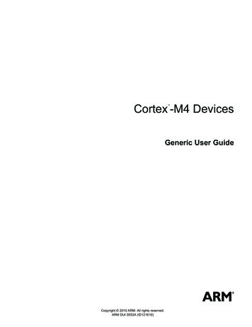
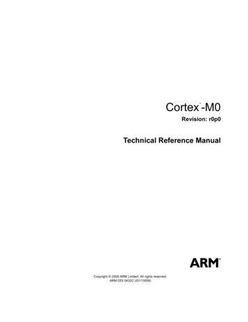
Functional Description2.1About the functionsThe Cortex-M0 processor is a configurable, multistage, 32-bit RISC processor. It has anAMBA AHB-Lite interface and includes an NVIC component. It also has optionalhardware debug functionality. The processor can execute Thumb code and iscompatible with other Cortex-M profile processors.Figure 2-1 shows the functional blocks of the processor.Cortex-M0 componentsCortex-M0 terrupts‡WakeupInterruptController tchpointunitBus matrix‡DebuggerinterfaceAHB-Lite interface‡DebugAccess Port(DAP)‡Serial Wire or JTAG debug port‡ Optional componentFigure 2-1 Functional block diagramThe implemented device provides: 2-2A low gate count processor that features:—The ARMv6-M Thumb instruction set.—Thumb-2 technology—Optionally, an ARMv6-M compliant 24-bit SysTick timer.—A 32-bit hardware multiplier. This can be the standard single-cyclemultiplier, or a 32-cycle multiplier that has a lower area and performanceimplementation.—The system interface supports either little-endian or byte invariantbig-endian data accesses.—The ability to have deterministic, fixed-latency, interrupt handling.—Load/store-multiples and multicycle-multiplies that can be abandoned andrestarted to facilitate rapid interrupt handling.—C Application Binary Interface compliant exception model.Copyright 2009 ARM Limited. All rights reserved.Non-Confidential, Unrestricted AccessARM DDI 0432CID113009
Functional DescriptionThis is the ARMv6-M, C Application Binary Interface (C-ABI) compliantexception model that enables the use of pure C functions as interrupthandlers.— ARM DDI 0432CID113009Low power sleep-mode entry using Wait For Interrupt (WFI), Wait ForEvent (WFE) instructions, or the return from interrupt sleep-on-exit feature.NVIC that features:—1, 2, 4, 8, 16, 24, or 32 external interrupt inputs, each with four levels ofpriority—dedicated Non-Maskable Interrupt (NMI) input—support for both level-sensitive and pulse-sensitive interrupt lines—optional Wake-up Interrupt Controller (WIC), providing ultra-low powersleep mode support.Optional debug support:—Zero to four hardware breakpoints.—Zero to two watchpoints.—Program Counter Sampling Register (PCSR) for non-intrusive codeprofiling, if at least one hardware data watchpoint is implemented.—Single step and vector catch capabilities.—Support for unlimited software breakpoints using BKPT instruction.—Non-intrusive access to core peripherals and zero-waitstate system slavesthrough a compact bus matrix. A debugger can access these devices,including memory, even when the processor is running.—Full access to core registers when the processor is halted.—Optional, low gate-count CoreSight compliant debug access through aDebug Access Port (DAP) supporting either Serial Wire or JTAG debugconnections.Bus interfaces:—single 32-bit AMBA-3 AHB-Lite system interface that provides simpleintegration to all system peripherals and memory—single 32-bit slave port that supports the DAP.Copyright 2009 ARM Limited. All rights reserved.Non-Confidential, Unrestricted Access2-3
Functional Description2.2InterfacesThis section describes the external interface functions.This manual does not include pinout and signal naming because each deviceimplementation can be different. See the Cortex-M0 Integration Manual or yourimplementers documentation for more information.2.2.1AHB-Lite interfaceTransactions on the AHB-Lite interface are always marked as non-sequential. Forinformation about the supported transactions, see the Cortex-M0 Integration Manual.Processor accesses and debug accesses share the external interface to external AHBperipherals. The processor accesses take priority over debug accesses.Any vendor specific components can populate this bus.2.2.2Debug Access PortThe processor has a low gate count Debug Access Port (DAP). This provides a SerialWire or JTAG debug-port, and connects to the processor slave port to provide fullsystem-level debug access.You can configure the processor slave port to connect to a full CoreSight DAP system,with the processor providing full multiprocessor debug simultaneous halt and releasecross-triggering capabilities.For more information on:2-4 DAP, see the ADI v5.1 version of the ARM Debug Interface v5, ArchitectureSpecification CoreSight DAP, see the ARM CoreSight Components Technical ReferenceManual.Copyright 2009 ARM Limited. All rights reserved.Non-Confidential, Unrestricted AccessARM DDI 0432CID113009
Chapter 3Programmers ModelThis chapter provides an overview of the application-level programmers model. Itcontains the following sections: About the programmers model on page 3-2 Modes of operation and execution on page 3-3 Instruction set summary on page 3-4 Memory model on page 3-9 Processor core registers summary on page 3-11 Exceptions on page 3-12.ARM DDI 0432CID113009Copyright 2009 ARM Limited. All rights reserved.Non-Confidential, Unrestricted Access3-1
Programmers Model3.1About the programmers modelThe ARMv6-M ARM provides a complete description of the programmers model. Thischapter gives an overview of the Cortex-M0 programmers model that describes theimplementation-defined options. It also contains the ARMv6-M Thumb instructions ituses and their cycle counts for the processor. In addition: Chapter 4 summarizes the system control features of the programmers model Chapter 5 summarizes the NVIC features of the programmers model Chapter 6 summarizes the Debug features of the programmers model.3-2Copyright 2009 ARM Limited. All rights reserved.Non-Confidential, Unrestricted AccessARM DDI 0432CID113009
Programmers Model3.2Modes of operation and executionSee the ARMv6-M Architecture Reference Manual for information about the modes ofoperation and execution.NoteOther ARM architectures support the concept of privileged or unprivileged softwareexecution. This processor does not support different privilege levels. Softwareexecution is always privileged, meaning software can access all the features of theprocessor.ARM DDI 0432CID113009Copyright 2009 ARM Limited. All rights reserved.Non-Confidential, Unrestricted Access3-3
Programmers Model3.3Instruction set summaryThe processor implements the ARMv6-M Thumb instruction set, including a numberof 32-bit instructions that use Thumb-2 technology. The ARMv6-M instruction setcomprises: all of the 16-bit Thumb instructions from ARMv7-M excluding CBZ, CBNZ and IT the 32-bit Thumb instructions BL, DMB, DSB, ISB, MRS and MSR.Table 3-1 shows the Cortex-M0 instructions and their cycle counts. The cycle countsare based on a system with zero wait-states.Table 3-1 Cortex-M0 instruction t immediateMOVS Rd, # imm 1Lo to LoMOVS Rd, Rm1Any to AnyMOV Rd, Rm1Any to PCMOV PC, Rm33-bit immediateADDS Rd, Rn, # imm 1All registers LoADDS Rd, Rn, Rm1Any to AnyADD Rd, Rd, Rm1Any to PCADD PC, PC, Rm38-bit immediateADDS Rd, Rd, # imm 1With carryADCS Rd, Rd, Rm1Immediate to SPADD SP, SP, # imm 1Form address from SPADD Rd, SP, # imm 1Form address from PCADR Rd, label 1Lo and LoSUBS Rd, Rn, Rm13-bit immediateSUBS Rd, Rn, # imm 18-bit immediateSUBS Rd, Rd, # imm 1With carrySBCS Rd, Rd, Rm1Immediate from SPSUB SP, SP, # imm 1AddSubtract3-4Copyright 2009 ARM Limited. All rights reserved.Non-Confidential, Unrestricted AccessARM DDI 0432CID113009
Programmers ModelTable 3-1 Cortex-M0 instruction summary ractNegateRSBS Rd, Rn, #01MultiplyMultiplyMULS Rd, Rm, Rd1 or 32aCompareCompareCMP Rn, Rm1NegativeCMN Rn, Rm1ImmediateCMP Rn, # imm 1ANDANDS Rd, Rd, Rm1Exclusive OREORS Rd, Rd, Rm1ORORRS Rd, Rd, Rm1Bi
ARMv6-M Instruction Set Quick Reference Guide (ARM QRC 0011) ARM AMBA 3 AHB-Lite Protocol Specification (ARM IHI 0033) ARM CoreSight Components Technical Reference Manual (ARM DDI 0314) ARM Debug Interface v5, Architecture Specification (ARM IHI 0031) Note A Cortex-M0 implemen tation can include a Debug Access Port (DAP .