Transcription
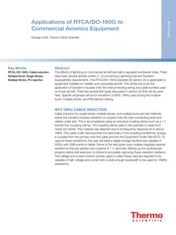
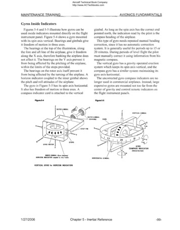
Aircraft Technical Book Companyhttp://www.ACTechbooks.comAVIONICS FUNDAMENTALSMAINTENANCE TRAININGGyros Inside IndicatorsFigures 5-4 and 5-5 illustrate how gyros can beused inside indicators mounted directly on the flightinstrument panel. Figure 5-4 shows a gyro mountedwith its spin axis vertical. Bearings and gimbals giveit freedom of motion in three axes.The bearings at the top of the illustration, alongthe fore and aft line of the airplane, give it freedomalong the X axis, therefore banking the airplane doesnot affect it. The bearings on the Y axis prevent itfrom being affected by the pitching of the airplane,within the limits of the stops provided.The bearings on the rotor axis itself prevent itfrom being affected by the turning of the airplane. Ahorizon indicator coupled to the inner gimbal showsthe pitch and roll attitudes of the airplane.The gyro in Figure 5-5 has its spin axis horizontal.It also has freedom of motion in three axes. Acompass indicator card is attached to the verticalgimbal. As long as the spin axis has the correct endpointed north, the indication read by the pilot is thecompass heading of the airplane.This type of gyro needs repeated manual headingcorrection, since it has no automatic correctionsystem. It is generally useful for periods up to 15 or20 minutes. During periods of level flight the pilotmust manually correct it using information from hismagnetic compass.The vertical gyro has a gravity operated erectionsystem which keeps its spin axis vertical, and thecompass gyro has a similar system maintaining itsgyro axis horizontal.The uncorrected gyro compass indicators are nolonger used in commercial airplanes. Instead, largeexpensive gyros are mounted not too far from thecenter of gravity and control remote indicators onthe flight instrument panels.Figure 5-5Figure 5-4Z'KOUTER,GIMBALVERTICAL GIMBALOUTER GIMBALBEARINGCARDFree STOP PINYSTOPSGYRO ROTORGYROCOMPASS INDICATOR(Uncorrected)I FreeINNER GIMBAL (Gyro housing)HORIZON INDICATOR coupled to this frameHORIZONTAL GIMBALVERTICAL GYRO for HORIZON INDICATION1/27/2006Chapter 5 - Inertial Reference-99-
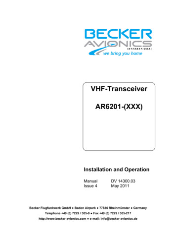
Aircraft Technical Book Companyhttp://www.ACTechbooks.comMAINTENANCE TRAININGAVIONICS FUNDAMENTALSGyro Horizon Indicator No. 1Figures 5-6 through 5-14 illustrate the indicationsgiven by a gyro horizon indicator for a variety of airplane attitudes. The inner portion of this indicator(and most others) is a movable part of a sphere. Aheavy black line represents the horizon, andseparates the light colored upper half from the darkcolored lower half The "W" with a dot in the centerand horizontal bars extending from the sidesrepresents the airplane. This symbol is in a fixedposition in front of the sphere.Figure 5-6 shows the airplane flying wings level("W" bars parallel with the horizon), and 6 nosedown. Pitch attitude is read on the scale drawn onthe sphere, at the point where the dot in the mi idleof the "W" is showing. In this case it is at the 6position below the horizon.Figure 5-7 shows the airplane flying wings 1 vel("W" bars parallel with the horizon), and nose in thehorizon ("W" dot on horizon line).Figure 5-8 shows the airplane flying wings 1 vel("W" bars parallel to the horizon), and 6 nose up("W" dot at the 6 position above the horizon).Figure 5-6HorizonPLANE—NOSED DOWNFigure 5-7HorizonA'NPLANE—FLYING LEVELFigure 5-8Horizon-100-PLANE—NOSED UPChapter 5 - Inertial Reference1/27 2006
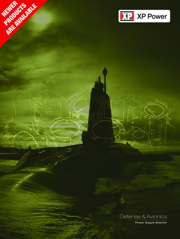
Aircraft Technical Book Companyhttp://www.ACTechbooks.comAVIONICS FUNDAMENTALSMAINTENANCE TRAININGGyro Horizon Indicator No. 2In Figures 5-9 and 5-10 the case of the indicatorhas been banked along with the airplane to showhow it would look to us if we could see through theairplane body to the instrument panel.In Figures 5-11 through 5-14 the indicator isdrawn to show how it appears to the pilot in theairplane.In Figure 5-9 the pilot sees that his left wing islower than his right wing and that the nose of theairplane is 6 below the horizon. The pilot reads hisbank angle at the top of the indicator. The index atthe top of the indicator is three spaces off to the rightFigure 5-9of center. Since each space represents 10 he is in a30 left bank.In Figure 5-10 the airplane is 6 nose down, whilein a 30 right bank.In Figure 5-11, the airplane nose is on the horizon,and the left wing is down 30 .In Figure 5-12, the airplane nose is also on thehorizon, but the right wing is down 30 .In Figure 5-13, the airplane nose is above thehorizon by 6 , while in a 30 left bank.In Figure 5-14, the airplane nose is above thehorizon 6 , while in a 30 right bank.Figure 5-10PLANE—BANKED LEFT (Nose down)PLANE—BANKED NIGHT (Nose down)HorizonHomanFigure 5-11Figure 5- 12PLANE—BANKED LEFT (Level)Figure 5-13PLANE-BANKED RIGHT (Level)Figure 5- 14HorizonPLANE—BANKED LEFT (Nose up)1/27/2006PLANE—BANKED RIGHT (Nose up)Chapter 5 - Inertial Reference-101-
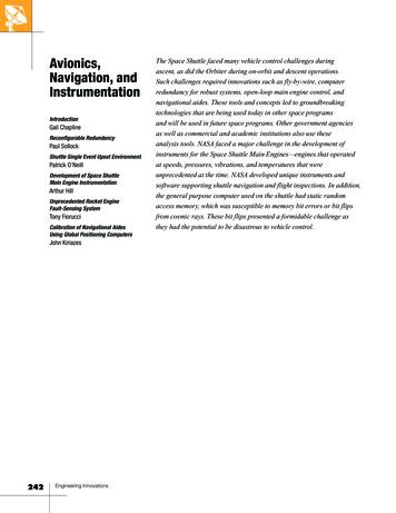
Aircraft Technical Book Companyhttp://www.ACTechbooks.comMAINTENANCE TRAININGAVIONICS FUNDAMENTALSRemote Gyro HorizonFigures 5-15 through 5-18 are photographs of alate model gyro horizon indicator. It is an integratedinstrument showing not only airplane pitch and rollattitude, but other indications as well.At the extreme bottom is a slip indicator. This is asimple device, with a ball enclosed in a curved tubefilled with a damping fluid, and a center positionindicated. If the ball is not centered, the aircraft isslipping or skidding to one side or the other, asituation which is infrequent in commercial aircraft.Just above that is a rate of turn indicator socalibrated that if the needle is directly below one ofthe outside dots, the airplane is turning at a rate of180 per minute in the direction indicated.Figure 5-16Figure 5-15PLANE—NOSE UP (Right wing down)PLANE—NOSE UP (Left wing down)Figure 5-18Figure 5-17PLANE—NOSE DOWN (Right wing down)-102-On the right is a glideslope deviation indicatr.On the left is a speed error indicator showingwhether the airplane is traveling faster or slowerthan a preselected speed.The upper right corner has a decision lightshowing when a preselected radio altitude abo e therunway has been reached on descent.On the left is a light which indicates whethe aflight director is turned on. The flight directorcommand hart also part of this instrument, areretracted from view in these pictures.There is provided a failure warning flag for achindication.At the lower left is the push-to-test button.PLANIE—NOSE DOWN (Left wing down)Chapter 5 - Inertial Reference1/27/2006
Aircraft Technical Book Companyhttp://www.ACTechbooks.comMAINTENANCE TRAININGAVIONICS FUNDAMENTALSRemote Vertical Gyro SchematicFigure 5-19 is a remote vertical gyro. It is called avertical gyro because its spin axis is automaticallymaintained vertically by gravity sensing pitch androll erection systems. The torquers and synchros arenot drawn, only their position is indicated.The black arrow pointing forward indicates thatthe inner gimbal bearing shafts must be aligned withthe fore and aft line of the airplane. This is so thatthe roll synchro will not be affected by pitch attitudechanges, and the pitch synchro will not be affectedby roll attitude changes.In order to maintain the spin axis vertically, twoerection systems must be used, one in the roll axisand one in the pitch axis. The obstinate reaction of agyro to an applied force (Figure 5-1) makes itnecessary to use erection forces at right angles to thedesired direction of motion. This accounts for thepitch erection torquer mounted in the roll axis, andthe roll erection torquer mounted in the pitch axis.A torquer is a frustrated motor. It never gets toturn anything, not even itself; but when called uponto do so, will try. A gravity sensing liquid switch,constructed on the principle of a carpenter's level,provides power to the torquer when the switch is notlevel. The torquer then provides the force to erect thespin axis vertically in one axis.Roll erection torquing is cut off when the bankangle exceeds about 6 to eliminate the tendency toerect to a false sense of vertical.Two types of signals are developed from the rolland pitch transmit synchros. The three legged signalis unambiguous in that any attitude through 360 could not be mistaken for any other attitude. Thesesignals are always used for controlling gyro horizonindicators. They will also be used by any othersystem where an unambiguous signal may be desired. The two legged error signals will be nullswhen the airplane is wings level and has its nose onthe horizon. For example, the roll transmit synchrois positioned in the gyro so that when the airplane iswings level, the voltages developed on the two upperlegs of the roll synchro are equal. There is, therefore,a null signal between them.An isolation transformer is used in the output tolessen possible bad effects on the three leggedsignal. If the airplane is banked to the right, thesevoltages are no longer equal, and the difference willbe of one phase. If the airplane is banked to the left,the voltages are no longer equal and the differencewill be of the other phase. Pitch error signals aredeveloped similarly.These error signals are ambiguous. For example,the phase and amplitude of a 5 right bank signal isthe same as the phase and amplitude of a 175 rightbank signal. Also, the phase and amplitude of an 85 right bank signal is the same as the phase andamplitude of a 95 right bank signal.Every signal developed has a twin at anotherattitude. However, within the first 90 of bank angleor pitch attitude, there is no ambiguity. Sincecommercial aircraft never bank or pitch beyond 90 ,some less critical systems can use these errorsignals, which are frequently more convenient.Figure 5-19ROLL ERECTIONTORQUER HereROLL POSITION SIGNAL11ROLL ERROR SIGNALPITCH ERROR SIGNAL}}PITCH POSITION SIGNALPITCH ERECTIONTORQUER Here1/27/2006Chapter 5 - Inertial Reference-103-
MAINTENANCE TRAINING AVIONICS FUNDAMENTALS Gyro Horizon Indicator No. 2 In Figures 5-9 and 5-10 the case of the indicator has been banked along with the airplane to show how it would look to us if we could see through the airplane body to the instrument panel. In Figures 5-11 through 5-14 the indicator is drawn to show how it appears to the pilot in the airplane. In Figure 5-9 the pilot sees .