Transcription
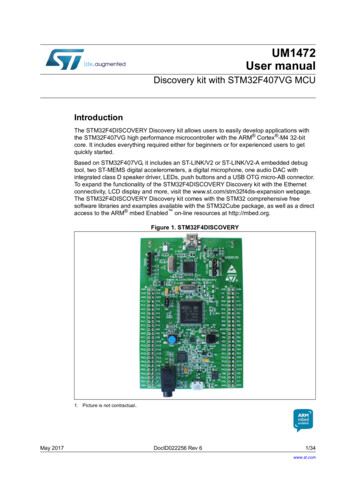
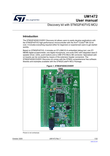
UM1472User manualDiscovery kit with STM32F407VG MCUIntroductionThe STM32F4DISCOVERY Discovery kit allows users to easily develop applications withthe STM32F407VG high-performance microcontroller with the Arm Cortex -M4 32-bitcore. It includes everything required either for beginners or experienced users to get startedquickly.Based on STM32F407VG, it includes an ST-LINK/V2-A embedded debug tool, one STMEMS digital accelerometer, one digital microphone, one audio DAC with integrated class Dspeaker driver, LEDs, push-buttons and a USB OTG Micro-AB connector. Specialized addon boards can be connected by means of the extension header connectors. TheSTM32F4DISCOVERY Discovery kit comes with the STM32 comprehensive free softwarelibraries and examples available with the STM32CubeF4 MCU Package.Figure 1. STM32F4DISCOVERYPicture is not contractual.October 2020UM1472 Rev 71/32www.st.com1
ContentsUM1472Contents1Features . . . . . . . . . . . . . . . . . . . . . . . . . . . . . . . . . . . . . . . . . . . . . . . . . . . 62Ordering information . . . . . . . . . . . . . . . . . . . . . . . . . . . . . . . . . . . . . . . . 72.13Codification . . . . . . . . . . . . . . . . . . . . . . . . . . . . . . . . . . . . . . . . . . . . . . . . . 7Development environment . . . . . . . . . . . . . . . . . . . . . . . . . . . . . . . . . . . . 83.1System requirements . . . . . . . . . . . . . . . . . . . . . . . . . . . . . . . . . . . . . . . . . 83.2Development toolchains . . . . . . . . . . . . . . . . . . . . . . . . . . . . . . . . . . . . . . . 83.3Demonstration software . . . . . . . . . . . . . . . . . . . . . . . . . . . . . . . . . . . . . . . 84Conventions . . . . . . . . . . . . . . . . . . . . . . . . . . . . . . . . . . . . . . . . . . . . . . . . 85Quick start . . . . . . . . . . . . . . . . . . . . . . . . . . . . . . . . . . . . . . . . . . . . . . . . . 95.16Hardware and layout . . . . . . . . . . . . . . . . . . . . . . . . . . . . . . . . . . . . . . . . 106.1Embedded ST-LINK/V2-A . . . . . . . . . . . . . . . . . . . . . . . . . . . . . . . . . . . . . 126.1.1Drivers . . . . . . . . . . . . . . . . . . . . . . . . . . . . . . . . . . . . . . . . . . . . . . . . . . 146.1.2ST-LINK/V2-A firmware upgrade . . . . . . . . . . . . . . . . . . . . . . . . . . . . . . 146.1.3ST-LINK/V2-A VCP configuration . . . . . . . . . . . . . . . . . . . . . . . . . . . . . 156.1.4Using ST-LINK/V2-A to program/debug the STM32F407VG on board . 166.1.5Using ST-LINK/V2-A to program/debug an external STM32 application 176.2Power supply and power selection . . . . . . . . . . . . . . . . . . . . . . . . . . . . . . 186.3LEDs . . . . . . . . . . . . . . . . . . . . . . . . . . . . . . . . . . . . . . . . . . . . . . . . . . . . 186.4Push buttons . . . . . . . . . . . . . . . . . . . . . . . . . . . . . . . . . . . . . . . . . . . . . . 186.5On-board audio capability . . . . . . . . . . . . . . . . . . . . . . . . . . . . . . . . . . . . 196.6USB OTG supported . . . . . . . . . . . . . . . . . . . . . . . . . . . . . . . . . . . . . . . . 196.7Motion sensor . . . . . . . . . . . . . . . . . . . . . . . . . . . . . . . . . . . . . . . . . . . . . . 196.8JP1 (Idd) . . . . . . . . . . . . . . . . . . . . . . . . . . . . . . . . . . . . . . . . . . . . . . . . . . 196.9OSC clock . . . . . . . . . . . . . . . . . . . . . . . . . . . . . . . . . . . . . . . . . . . . . . . . 206.102/32Getting started . . . . . . . . . . . . . . . . . . . . . . . . . . . . . . . . . . . . . . . . . . . . . . 96.9.1OSC clock supply . . . . . . . . . . . . . . . . . . . . . . . . . . . . . . . . . . . . . . . . . 206.9.2OSC 32 KHz clock supply . . . . . . . . . . . . . . . . . . . . . . . . . . . . . . . . . . . 20Solder bridges . . . . . . . . . . . . . . . . . . . . . . . . . . . . . . . . . . . . . . . . . . . . . 21UM1472 Rev 7
UM1472Contents6.11Extension connectors . . . . . . . . . . . . . . . . . . . . . . . . . . . . . . . . . . . . . . . . 217Mechanical drawing . . . . . . . . . . . . . . . . . . . . . . . . . . . . . . . . . . . . . . . . 288STM32F4DISCOVERY Discovery kit information . . . . . . . . . . . . . . . . . 298.1Product marking . . . . . . . . . . . . . . . . . . . . . . . . . . . . . . . . . . . . . . . . . . . . 298.2Board revision history . . . . . . . . . . . . . . . . . . . . . . . . . . . . . . . . . . . . . . . . 298.2.1MB997 . . . . . . . . . . . . . . . . . . . . . . . . . . . . . . . . . . . . . . . . . . . . . . . . . . 29Appendix A Federal Communications Commission (FCC) and ISED CanadaCompliance Statements30A.1A.29FCC Compliance Statement . . . . . . . . . . . . . . . . . . . . . . . . . . . . . . . . . . . 30A.1.1Part 15.19 . . . . . . . . . . . . . . . . . . . . . . . . . . . . . . . . . . . . . . . . . . . . . . . . 30A.1.2Part 15.21 . . . . . . . . . . . . . . . . . . . . . . . . . . . . . . . . . . . . . . . . . . . . . . . . 30A.1.3Part 15.105 . . . . . . . . . . . . . . . . . . . . . . . . . . . . . . . . . . . . . . . . . . . . . . . 30ISED Compliance Statement. . . . . . . . . . . . . . . . . . . . . . . . . . . . . . . . . . . 30Revision history . . . . . . . . . . . . . . . . . . . . . . . . . . . . . . . . . . . . . . . . . . . 31UM1472 Rev 73/323
List of tablesUM1472List of tablesTable 1.Table 2.Table 3.Table 4.Table 5.Table 6.Table 7.Table 8.4/32Ordering information . . . . . . . . . . . . . . . . . . . . . . . . . . . . . . . . . . . . . . . . . . . . . . . . . . . . . . . 7Codification explanation . . . . . . . . . . . . . . . . . . . . . . . . . . . . . . . . . . . . . . . . . . . . . . . . . . . . 7ON/OFF conventions . . . . . . . . . . . . . . . . . . . . . . . . . . . . . . . . . . . . . . . . . . . . . . . . . . . . . . 8Jumper states . . . . . . . . . . . . . . . . . . . . . . . . . . . . . . . . . . . . . . . . . . . . . . . . . . . . . . . . . . . 13Debug connector CN2 (SWD) . . . . . . . . . . . . . . . . . . . . . . . . . . . . . . . . . . . . . . . . . . . . . . 17Solder bridges. . . . . . . . . . . . . . . . . . . . . . . . . . . . . . . . . . . . . . . . . . . . . . . . . . . . . . . . . . . 21STM32 pin description versus board functions . . . . . . . . . . . . . . . . . . . . . . . . . . . . . . . . . . 22Document revision history . . . . . . . . . . . . . . . . . . . . . . . . . . . . . . . . . . . . . . . . . . . . . . . . . 31UM1472 Rev 7
UM1472List of figuresList of figuresFigure 1.Figure 2.Figure 3.Figure 4.Figure 5.Figure 6.Figure 7.Figure 8.Figure 9.STM32F4DISCOVERY . . . . . . . . . . . . . . . . . . . . . . . . . . . . . . . . . . . . . . . . . . . . . . . . . . . . . 1Hardware block diagram . . . . . . . . . . . . . . . . . . . . . . . . . . . . . . . . . . . . . . . . . . . . . . . . . . 10STM32F4DISCOVERY top layout . . . . . . . . . . . . . . . . . . . . . . . . . . . . . . . . . . . . . . . . . . . 11STM32F4DISCOVERY bottom layout . . . . . . . . . . . . . . . . . . . . . . . . . . . . . . . . . . . . . . . . 12USB composite device . . . . . . . . . . . . . . . . . . . . . . . . . . . . . . . . . . . . . . . . . . . . . . . . . . . . 14ST-LINK VCP connection to USART2 . . . . . . . . . . . . . . . . . . . . . . . . . . . . . . . . . . . . . . . . 15STM32F4DISCOVERY connections . . . . . . . . . . . . . . . . . . . . . . . . . . . . . . . . . . . . . . . . . 16ST-LINK connections . . . . . . . . . . . . . . . . . . . . . . . . . . . . . . . . . . . . . . . . . . . . . . . . . . . . . 17STM32F4DISCOVERY mechanical drawing . . . . . . . . . . . . . . . . . . . . . . . . . . . . . . . . . . . 28UM1472 Rev 75/325
Features1UM1472FeaturesThe STM32F4DISCOVERY offers the following features: STM32F407VGT6 microcontroller featuring 32-bit Arm (a) Cortex -M4 with FPU core,1-Mbyte Flash memory, 192-Kbyte RAM in an LQFP100 package USB OTG FS ST MEMS 3-axis accelerometer ST-MEMS audio sensor omni-directional digital microphone Audio DAC with integrated class D speaker driver User and reset push-buttons Eight LEDs:–LD1 (red/green) for USB communication–LD2 (red) for 3.3 V power on–Four user LEDs, LD3 (orange), LD4 (green), LD5 (red) and LD6 (blue)–Two USB OTG LEDs, LD7 (green) VBUS and LD8 (red) over-current Board connectors:–USB with Micro-AB–Stereo headphone output jack– 2.54 mm pitch extension header for all LQFP100 I/Os for quick connection toprototyping board and easy probingFlexible power-supply options: ST-LINK, USB VBUS, or external sourcesExternal application power supply: 3 V and 5 VComprehensive free software including a variety of examples, part of STM32CubeF4MCU Package, or STSW-STM32068 for using legacy standard librariesOn-board ST-LINK/V2-A debugger/programmer with USB re-enumeration capability:mass storage, Virtual COM port, and debug portSupport of a wide choice of Integrated Development Environments (IDEs) including IAREmbedded Workbench , MDK-ARM, and STM32CubeIDEa. Arm is a registered trademark of Arm Limited (or its subsidiaries) in the US and or elsewhere.6/32UM1472 Rev 7
UM14722Ordering informationOrdering informationTo order the Discovery kit for the STM32F407 product line of microcontrollers, refer toTable 1. Additional information is available from the datasheet and reference manual of thetarget microcontroller.Table 1. Ordering informationOrder codeBoard referenceTarget STM32STM32F407G-DISC1(1)MB997STM32F407VGT61. STM32F407G-DISC1 with ST-LINK/V2-A replaces the obsolete STM32F4DISCOVERY order code withST-LINK/V2.2.1CodificationThe meaning of the codification is explained in Table 2.Table 2. Codification ionExample: STM32F407G-DISC1MCU series in STM32 32-bit Arm CortexSTM32F4 SeriesMCUsMCU product line in the seriesSTM32F407STM32 Flash memory size:– G for 1 Mbyte1 MbyteDiscovery kitDiscovery kitUM1472 Rev 77/3231
Development environmentUM14723Development environment3.1System requirements3.23.3 Windows OS (7, 8 and 10), Linux 64-bit, or macOS (a) USB Type-A or USB Type-C to Mini-B cableDevelopment toolchains IAR Systems - IAR Embedded Workbench (b) Keil - MDK-ARM(b) STMicroelectronics - STM32CubeIDEDemonstration softwareThe demonstration software, included in the STM32Cube MCU Package corresponding tothe on-board microcontroller, is preloaded in the STM32 Flash memory for easydemonstration of the device peripherals in standalone mode. The latest versions of thedemonstration source code and associated documentation can be downloaded fromwww.st.com.4ConventionsTable 3 provides the definition of some conventions used in the present document.Table 3. ON/OFF conventionsConventionDefinitionJumper JP1 ONJumper fittedJumper JP1 OFFJumper not fittedSolder bridge SBx ONSBx connections closed by solderSolder bridge SBx OFF SBx connections left opena. macOS is a trademark of Apple Inc. registered in the U.S. and other countries.All other trademarks are the property of their respective owners.b. On Windows only.8/32UM1472 Rev 7
UM14725Quick startQuick startThe STM32F4DISCOVERY is a low-cost and easy-to-use development kit to quicklyevaluate and start a development with an STM32F407VGT6 high-performancemicrocontroller.Before installing and using the product, accept the Evaluation Product License Agreementfrom the www.st.com/stm32f4-discovery webpage.For more information on the STM32F4DISCOVERY and for demonstration software, visitthe www.st.com/stm32f4-discovery webpage.5.1Getting startedFollow the sequence below to configure the STM32F4DISCOVERY board and launch theDISCOVER application:1.Check the jumpers positions on the board: JP1 ON, CN3 ON (DISCOVERY selected).2.Connect the STM32F4DISCOVERY board to a PC with a USB cable ‘Type-A to Mini-B’through USB connector CN1 to power the board. Red LED LD2 (PWR) then lights up.3.Four LEDs between buttons B1 and B2 are blinking.4.Press user button B1 to enable the ST MEMS sensor, move the board and observe thefour LEDs blinking according to the motion direction and speed. (If a second USB cable‘Type-A to Micro-B’ is connected between the PC and CN5 connector, then the board isrecognized as a standard mouse and its motion will also control the PC cursor).5.To study or modify the DISCOVER project related to this demonstration, visit thewww.st.com/stm32f4-discovery webpage and follow the tutorial.6.Discover the STM32F407VG features, download and execute programs proposed inthe list of projects.7.Develop the application using available examples.UM1472 Rev 79/3231
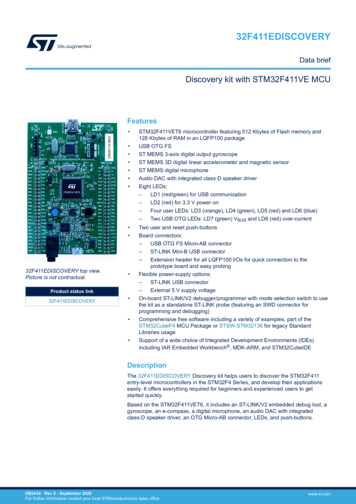
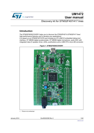
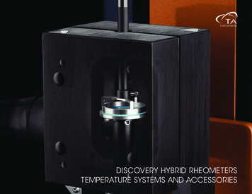
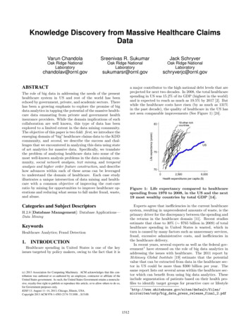
Hardware and layout6UM1472Hardware and layoutThe STM32F4DISCOVERY is designed around the STM32F407VGT6 microcontroller in a100-pin LQFP package.Figure 2 illustrates the connections between the STM32F407VGT6 and its peripherals (STLINK/V2-A, push buttons, LEDs, audio DAC, USB, ST-MEMS accelerometer andmicrophone, and connectors).Figure 3 and Figure 4 help users to locate these features on the STM32F4DISCOVERYboard.Figure 2. Hardware block I/ORESETLEDsLD3 to LD8B2RSTAudio sensorB1USERAudio DACMini-JackHeaderI/OHeaderI/OMotion sensorMicro-USBMSv30007V310/32UM1472 Rev 7
UM1472Hardware and layoutFigure 3. STM32F4DISCOVERY top layoutST-LINK/V2LD1 (red/green LED)COMCN2SWD connectorSTM32F407G-DISC1LD2 (red 8PA9PC8PC9PC6PC7GNDGND5V powersupply input/output3V powersupply outputSB1 (B2-RESET)LD3(orange 6LD7R64R63C60R65U9LD8
the www.st.com/stm32f4-discovery webpage. 5.1 Getting started Follow the sequence below to configure the STM32F4DISCOVERY board and launch the DISCOVER application: 1. Check the jumpers positions on the board: JP1 ON, CN3 ON (DISCOVERY selected). 2. Connect the STM32F4DISCOVERY board to a PC with a USB cable ‘Type-A to Mini-B’