Transcription
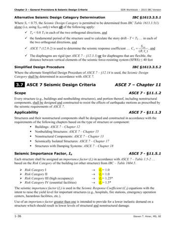
Chapter 3 – General Provisions & Seismic Design CriteriaSDR Workbook – 2015 IBC VersionAlternative Seismic Design Category DeterminationIBC §1613.3.5.1Where S1 0.75, the Seismic Design Category is permitted to be determined from IBC Table 1613.3.5(1)alone (i.e, using SDS only) when all of the following apply: Ta 0.8 TS in each of the two orthogonal directions, and the fundamental period of the structure used to calculate the story drift - T TS in each ofthe two orthogonal directions, andS ASCE 7 (12.8-2) is used to determine the seismic response coefficient CS DS , and(R Ie ) The diaphragms are rigid (per ASCE 7 – §12.3.1) or for diaphragms that are flexible, thedistance between vertical elements of the seismic force-resisting system (SFRS) 40 feetSimplified Design ProcedureIBC §1613.3.5.2Where the alternate Simplified Design Procedure of ASCE 7 – §12.14 is used, the Seismic DesignCategory shall be determined in accordance with ASCE 7.3.7 ASCE 7 Seismic Design CriteriaASCE 7 – Chapter 11ScopeASCE 7 - §11.1.2Every structure (e.g., buildings and nonbuilding structures), and portion thereof, including nonstructuralcomponents, shall be designed and constructed to resist the effects of earthquake motions as prescribed bythe seismic requirements of ASCE 7.ApplicabilityASCE 7 - §11.1.3Structures and their nonstructural components shall be designed and constructed in accordance with therequirements of the following chapters based on the type of structure or component: Buildings: ASCE 7 – Chapter 12 Nonbuilding Structures: ASCE 7 – Chapter 15 Nonstructural Components: ASCE 7 – Chapter 13 Seismically Isolated Structures: ASCE 7 – Chapter 17 Structures with Damping Systems: ASCE 7 – Chapter 18Seismic Importance Factor, IeASCE 7 - §11.5.1Each structure shall be assigned an importance factor (Ie) in accordance with ASCE 7 – Table 1.5-2 based on the Risk Category of the building (or other structure) from IBC – Table 1604.5. Risk Category IRisk Category IIRisk Category III (high occupancy)Risk Category IV (essential facilities) Ie 1.0Ie 1.0Ie 1.25*Ie 1.5*The seismic importance factor (Ie) is used in the Seismic Response Coefficient (CS) equations with theintent to raise the yield level for important structures (e.g., hospitals, fire stations, emergency operationcenters, hazardous facilities, etc.).Use of an importance factor greater than one is intended to provide for a lower inelastic demand on astructure which should result in lower levels of structural and nonstructural damage.1-36Steven T. Hiner, MS, SE
Chapter 4 – Seismic Design Requirements for Building StructuresSDR Workbook – 2015 IBC VersionApproximate Fundamental Period, TaASCE 7 – §12.8.2.1The approximate fundamental period shall be determined by the following:Ta Ct hnxASCE 7 (12.8-7)where:Ct & x are determined from ASCE 7 – Table 12.8-2hn height in feet, from the base to the uppermost level of the structureNOTE: See Table C1 – Approximate Fundamental Period, Ta (Appendix C, p. 5-17) for tabulated valuesof ASCE 7 (12.8-7). Steel Moment-Resisting Frames (SMF, IMF & OMF) –Ta 0.028hn0.8Or alternatively (for Steel MRF structures 12 stories and average story height 10 feet):Ta 0.1NASCE 7 (12.8-8)where:N number of stories (i.e., levels) above the base Concrete Moment-Resisting Frames (SMF, IMF & OMF) –Ta 0.016hn0.9Or alternatively (for Concrete MRF structures 12 stories and average story height 10 feet):Ta 0.1N ASCE 7 (12.8-8)Steel EBF, Steel BRBF, or Dual System w/ EBF & SMF –Ta 0.03hn0.75 All Other Structural Systems – (e.g., shear walls, CBF, Dual Systems)Ta 0.02hn0.75NOTE: Refer to ASCE 7 – §12.8.2.1 and equations (12.8-9) & (12.8-10) for an alternative method ofcalculating Ta for structures with concrete or masonry shear walls.4.10Actual vs. Design Seismic ForcesThe Risk-Targeted Maximum Considered Earthquake (MCER) ground motion is the most severeearthquake effects considered by the IBC & ASCE 7.The basis for the mapped MCER ground motions in ASCE 7-10 is significantly different from that of themapped MCE ground motions in ASCE 7-05 and previous editions of ASCE 7. The MCER probabilisticground motions are based on a uniform collapse risk (e.g., 1% probability of collapse in 50 years), ratherthan a uniform hazard (e.g., 2% probability of being exceeded in 50 years). The assumption is thatbuildings designed in accordance with ASCE 7-10 have a collapse probability of not more than 10% (onaverage) if MCER ground motions were ever to occur at the building site.In regions of high seismicity (e.g., many areas of California), the seismic hazard is typically controlled bylarge magnitude events occurring on a limited number of well defined fault systems. For these regions, itis considered more appropriate to use deterministic MCER ground motions where a collapse probability of1-56Steven T. Hiner, MS, SE
Chapter 5 – Earthquake Loads and Load CombinationsSDR Workbook – 2015 IBC VersionEv effect of vertical seismic forces (i.e., due to vertical ground motions) as defined inASCE 7 – §12.4.2.2. Ev can be positive or negative due to the cyclic nature of(vertical) seismic ground motions.Horizontal Seismic Load Effect with Overstrength Factor, EmhASCE 7 – §12.4.3.1The horizontal seismic load effect with overstrength factor (Emh) shall be determined in accordance withthe following: Emh 0QEASCE 7 (12.4-7)where:QE effects of horizontal seismic forces from the seismic base shear V (per ASCE 7 –§12.8.1) or the seismic lateral force Fp (per ASCE 7 – §13.3.1). See ASCE 7 – §12.5.3& ASCE 7 – §12.5.4 for consideration of orthogonal effects) 0 overstrength factor per ASCE 7 – Table 12.2-1Exception: Emh need not exceed the maximum force that can develop in the element asdetermined by see ASCE 7 – §12.4.3.15.2 Load CombinationsGeneralIBC §1605IBC §1605.1Buildings (and other structures) and portions thereof shall be designed to resist the load combinationsspecified in: IBC §1605.2 (Strength Design or Load & Resistance Factor Design – SD/LRFD) orIBC §1605.3 (Allowable Stress Design – ASD), andIBC Chapters 18 through 23, andThe seismic load effects including overstrength factor ( 0) in accordance with ASCE 7 – §12.4.3where required by ASCE 7 – §12.2.5.2, §12.3.3.3, or ASCE 7 – §12.10.2.1NOTE: When using the Simplified Procedure of ASCE 7 – §12.14, the seismic load effects includingoverstrength factor of ASCE 7 – §12.14.3.2 shall be used (i.e., 0 2.5 assumed).Load combinations are a way of considering the maximum (or minimum) forces on a structural elementusing principles of superposition.The load combinations consider combined effects of gravity loads (e.g., dead load, floor live load, rooflive load, rain load, snow load) and other load effects as a result of earthquake, wind, flood, earthpressure, fluid pressure, etc.Notations –D Dead loadE Combined effect of horizontal and vertical earthquake induced forces as defined inASCE 7 – §12.4.2F Load due to fluids with well-defined pressures and maximum heightsFa Flood load in accordance with ASCE 7 – Chapter 5H Load due to earth pressure, ground water pressure, or pressure of bulk materialsL Floor live load, and roof live load 20 psf1-74Steven T. Hiner, MS, SE
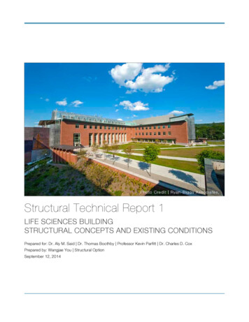
SDR Workbook – 2015 IBC VersionChapter 8 – Diaphragm Design & Wall RigidityChapter 8Diaphragm Design & Wall Rigidity8.1 Diaphragm DesignASCE 7 – §12.10.1Diaphragms shall be designed for both the shear and bending stresses resulting from design forces.Diaphragm Design Force, FpxStrength Design force levelFloor and roof diaphragms shall be designed to resist design seismic forces from the structural analysis,but shall not be less than that determined in accordance with the following:nFpx Fi xni wi xw pxASCE 7 (12.10-1)iThe diaphragm design force shall not be less than:Fpx 0.2 S DS I e w px minimumASCE 7 (12.10-2)The diaphragm design force need not exceed:Fpx 0.4 S DS I e w px maximumwhere:ASCE 7 (12.10-3)wpx weight of the diaphragm and the elements tributary thereto at Level x includingapplicable portions of other loads from ASCE 7 – §12.7.2 (e.g., 25% of floor live load forstorage/warehouse, 10 psf minimum for partitions, total operating weight of permanentequipment, 20% of design snow load where Pf 30 psf, etc.).Figure 8.1 – Diaphragm Design Force F F3 F4 F5 w p 2Fp 2 2 w2 w3 w4 w5 Steven T. Hiner, MS, SE1-105
SDR Workbook – 2015 IBC VersionChapter 9 – IBC Chapter 23 – WoodThe weight of the wall (WW) can be considered a dead load effect (D). While the weight of the wall mightbe considered in the determination of the total seismic force on the shear wall (i.e., V1 CS WW), it willnot be used to determine Ev because the dead load effect (D) does not contribute to the determination ofthe calculated unit wall shear.NOTE: The Redundancy factor ( ) shall be considered in the design of the shear walls.Therefore, E E h QE V1 So the ASD calculated unit wall shear:ASD calculated wall (0.7)(total wall shear) shear wall width (0.7 V1 ) b(units of plf)sNOTE: The equation above is used to determine the drag force, and may be used for shear wall designwhen the wall weight (Ww) is not significant, not given in a problem statement, or when the diaphragmdesign force (e.g., ws fpx Fpx / L) includes all perimeter walls of the building essentially when thebase shear (V ) is used to design the diaphragm.Otherwise, the weight of the shear wall (Ww) can be included in the ASD calculated unit wall shear:ASD calculated wall (0.7)(V1 CSWW ) b(units of plf)sUsing the ASD calculated wall and SDPWS Table 4.3A (see Table 9.5), choose the appropriate: WSP panel gradeWSP nominal panel thicknessFastener (nail) sizeFastener (nail) spacingSuch that the ASD allowable wall ASD calculated wall Shear Walls in a LineSDPWS §4.3.3.4The shear distribution to individual shear walls in a shear wall line shall provide the same calculateddeflection (δsw) in each shear wall (i.e., the shear force shall be distributed based on the relative stiffnessesof the individual shear walls).Alternatively, where nominal shear capacities of all WSP shear walls with aspect ratios h/bs 2:1 aremultiplied by 2bs/h for design, shear distribution to individual full-height (shear) wall segments shall bepermitted to be taken as proportional to the shear capacities of the individual full height wall segmentsused in design, and the nominal shear capacities need not be reduced by the ARFWSP in SDPWS §4.3.4.2. h/bs 2:1 use nominal unit shear capacities from SDPWS Table 4.3A with no reduction 2:1 h/bs 3.5:1 use nominal unit shear capacities from SDPWS Table 4.3A multiplied by 2bs/hExample - given two WSP shear walls on same wall line. Wall A: h 12′ & bs 7′ and Wall B: h 12′& bs 4′. Determine the percent shear in each shear wall with an applied total shear of V1 assumingboth shear walls use the same WSP and nailing with a nominal capacity of 520 plf: Wall A: h/bs (12′ / 7′) 1.71 2:1 no unit shear capacity reduction necessaryCapacity of Wall A 520 plf (bs) 520 plf (7′) 3,640 lbsSteven T. Hiner, MS, SE1-139
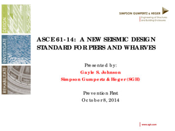
Chapter 10 – Other Material ChaptersSDR Workbook – 2015 IBC VersionHoop - closed tie reinforcement that provides strength for shear and confinement for the concretecore.Confinement - provides for the ductile performance of members and increases the compressivestrength of the confined concrete which helps to compensate for strength loss due to the "spalled"outer concrete shell.Strong Column - Weak Beam DesignACI 318-14 – §18.7.3.2Intent is to confine flexural yielding (inelastic) to the beams while the columns remain elastic throughouttheir seismic response.At any beam/column joint: Mnc (6/5) MnborACI 318 (18.7.3.2) nominal flexural strength of 6 nominal flexural strength of columns framing into the joint 5 beams framing into the joint Intermediate Moment Frames (IMF)(Not permitted in Seismic Design Category D, E & F) ACI 318-14 – §18.4R 5 for reinforced concrete IMFLimited special detailing of beam-column joint, therefore limited ductility (i.e., lower R).Ordinary Moment Frames (OMF)(Not permitted in Seismic Design Category C, D, E & F) ACI 318-14 – §18.3R 3 for reinforced concrete OMFNo special detailing of beam-column joint, therefore very limited ductility (i.e., very low R).Special Reinforced Concrete Shear Walls(Typically required in Seismic Design Category D, E & F)ACI 318-14 – §18.10Special reinforced concrete structural walls (i.e., shear walls) need to comply with the requirements ofACI 318 – §18.2.3 through §18.2.8 and §18.10. R 5 for special reinforced concrete shear walls - Bearing Wall SystemR 6 for special reinforced concrete shear walls - Building Frame SystemFigure 10.4 – Special Reinforced Concrete Shear Wall1-160Steven T. Hiner, MS, SE
SDR Workbook – 2015 IBC VersionIntermediate Reinforced Masonry Shear Walls(Not permitted in Seismic Design Category D, E & F) ACI 530-13 – §7.3.2.5R 3½ for intermediate reinforced masonry shear walls - Bearing Wall SystemR 4 for intermediate reinforced masonry shear walls - Building Frame SystemOrdinary Reinforced Masonry Shear Walls(Not permitted in Seismic Design Category D, E & F) Chapter 10 – Other Material ChaptersACI 530-13 – §7.3.2.4R 2 for ordinary reinforced masonry shear walls - Bearing Wall SystemR 2 for ordinary reinforced masonry shear walls - Building Frame SystemFigure 10.6 – 8 x 8 x 16 Concrete Masonry Units (CMU)10.4 IBC Chapter 22 – SteelGeneralIBC §2205.1The design, fabrication and erection of structural steel elements of buildings, structures and portionsthereof shall be in accordance with AISC 360-10 – Specification for Structural Steel Buildings (includedin the AISC Steel Construction Manual).Structural Steel Seismic Force-Resisting SystemsIBC §2205.2.1The design, detailing, fabrication and erection of structural steel seismic force-resisting systems shall bein accordance with the provisions of IBC §2205.2.1.1 or §2205.2.1.2.Seismic Design Category B or C –IBC §2205.2.1.1Structures assigned to SDC B or C shall be of any construction permitted in IBC §2205.Where a response modification factor (R) in accordance with ASCE 7-10 – Table 12.2.1 is used for thedesign the structures shall be designed and detailed in accordance with the requirements of AISC 34110 – Seismic Provisions for Structural Steel Buildings. See IBC §2205.2.1.1 - Exception for “structuralsteel systems not specifically detailed for seismic resistance, excluding cantilever column systems” perASCE 7-10 – Table 12.2-1, item H.Steven T. Hiner, MS, SE1-163
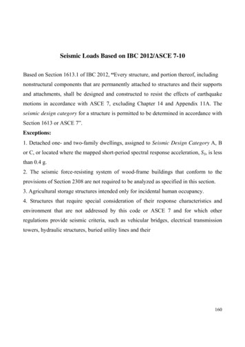
Chapter 10 – Other Material ChaptersSDR Workbook – 2015 IBC VersionSeismic Design Category D, E or F –IBC §2205.2.1.2Structures assigned to SDC D, E or F shall be designed and detailed in accordance with AISC 341-10 –Seismic Provisions for Structural Steel Buildings (included in the AISC Seismic Design Manual), exceptas permitted in ASCE 7-10 – Table 15.4-1 (i.e., for nonbuilding structures similar to buildings).Composite Structural Steel & Concrete StructuresIBC §2206GeneralIBC §2206.1Systems of structural steel elements acting compositely with reinforced concrete shall be designed inaccordance with: AISC 360-10 – Specification for Structural Steel Buildings, and ACI 318-14 – Building Code Requirements for Structural Concrete (excluding Chapter 14)Where required, the seismic design, fabrication and erection of composite steel and concrete systems shallbe in accordance with IBC 2206.2.1.Seismic requirementsIBC §2206.2.1Where a response modification coefficient R (per ASCE 7 – Table 12.2-1) is used for the design ofsystems of structural steel acting compositely with reinforced concrete, the structures shall be designedand detailed in accordance with the requirements of AISC 341-10 – Seismic Provisions for StructuralSteel Buildings.Special Moment Frames (SMF)(Typically required in Seismic Design Category D, E & F) AISC 341-10 – §E.3R 8 for steel SMFSMF’s are expected to withstand significant inelastic deformations when subjected to the Design BasisEarthquake ground motions. Beam-column joints and members are designed to behave in a ductilemanner.Figure 10.7 – Steel Beam-Column Joint (pre-Northridge)1-164Steven T. Hiner, MS, SE
SDR Workbook – 2015 IBC VersionChapter 10 – Other Material ChaptersNOTE: Following the January 17, 1994 Northridge Earthquake, over 100 steel buildings with weldedmoment-resisting frames were found to have beam-to-column connection fractures. Usually the fracturesinitiated at the complete joint penetration weld between the beam bottom flange and the column flange.Investigators have suggested that the fractures may be due to a number of factors such as notch effectscreated by a left in place weld backing bar; sub-standard welding (excessive porosity, slag inclusions,incomplete fusion); and/or pre-earthquake fractures due to initial shrinkage of the weld during cool-down.In September 1994, the International Conference of Building Officials (ICBO) adopted an emergencycode change to the 1994 Uniform Building Code (UBC). This code change omitted the pre-qualifiedconnection (see Figure 10.7) and required that connections be designed to sustain inelastic rotation anddevelop the strength criteria as demonstrated by cyclic testing or calculation.In November 2000, the SAC Joint Venture finalized the welded steel moment frame issues which werepublished by the Federal Emergency Management Agency (FEMA) in the following documents: FEMA 350 – Recommended Seismic Design Criteria for New Steel Moment-Frame Buildings FEMA 351 – Recommended Seismic Evaluation and Upgrade Criteria for Existing Welded SteelMoment-Frame Buildings FEMA 352 – Recommended Post-Earthquake Evaluation and Repair Criteria for Welded SteelMoment-Frame Buildings FEMA 353 – Recommended Specifications and Quality Assurance Guidelines for Steel MomentFrame Construction for Seismic ApplicationsDoubler PlatesDoubler plates are sometimes added to one (or both sides) of the column web and are intended to increasethe column’s web shear strength and web crippling capacity within the panel zone.Continuity PlatesContinuity plates are sometimes added to provide “continuity” of the intersecting beam (or girder) flangesacross the column web. The requirement for continuity plates is a function of the column yield strength,flange width, and flange thickness, and the intersecting beam yield strength, flange width, and flangethickness.Intermediate Moment Frames (IMF) AISC 341-10 – §E.2R 4½ for steel IMF*IMF’s are expected to withstand limited inelastic deformations (in their members and connections) whensubjected to the Design Basis Earthquake ground motions.Limited special detailing of beam-column joint, therefore limited ductility (i.e., lower R).Ordinary Moment Frames (OMF) AISC 341-10 – §E.1R 3½ for steel OMF*OMF’s are expected to withstand minimal inelastic deformations (in their members and connections)when subjected to the Design Basis Earthquake ground motions.Very limited special detailing of beam-column joint, therefore very limited ductility (i.e., very low R).*NOTE: Typically steel IMF’s and OMF’s will not be permitted in structures assigned to Seismic DesignCategory D, E or F with the exception of steel OMF’s meeting the requirements of ASCE 7 –§12.2.5.6.1 for SDC D or E or §12.2.5.6.2 for SDC F, and steel IMF’s meeting requirements of ASCE7 – §12.2.5.7.1 for SDC D or §12.2.5.7.2 for SDC E or §12.2.5.7.3 for SDC F.Steven T. Hiner, MS, SE1-165
SDR Workbook – 2015 IBC VersionChapter 11 – IBC Inspection & Observation Requirements1. Structural Steel - special inspections for seismic resistance of: Seismic force-resisting systems (SFRS) of buildings & structures assigned to SDC B, C, D,E or F in accordance with the quality assurance requirements of AISC 341-10. Structural steel elements in the SFRS of buildings & structures assigned to SDC B, C, D, Eor F (other than the SFRS elements covered above including struts, collectors, chords andfoundation elements) in accordance with the quality assurance requirements of AISC 341-10.2. Structural wood - for the SFRS of structures assigned to SDC C, D, E or F per IBC §1705.12.2.Exception: When sheathing fastener spacing is 4″ o.c., special inspections are not requiredfor wood shear walls, shear panels and diaphragms, including nailing, bolting, anchoring, andother fastening to other components of the SFRS.3. Cold-formed steel light-frame construction - periodic special inspection for the SFRS ofstructures assigned to SDC C, D, E or F per IBC §1705.12.3.4. Designated seismic systems - for structures assigned to SDC C, D, E or F per IBC §1705.12.4.5. Architectural components - periodic special inspection for the erection and fastening of exteriorcladding, interior and exterior nonbearing walls, and interior and exterior veneer in structuresassigned to SDC D, E or F.6. Plumbing, mechanical and electrical components - periodic special inspection in structuresassigned to SDC C, D, E or F per IBC §1705.12.6.7. Storage racks - periodic special inspection for the anchorage of storage racks 8 feet in height instructures assigned to SDC D, E or F.8. Seismic isolation systems - periodic special inspection for seismically isolated (i.e., base isolated)structures assigned to SDC B, C, D, E or F.9. Cold-formed steel special bolted moment frames - periodic special inspection for the SFRS ofstructures assigned to SDC D, E or F.Exception: Special inspections noted above are not required for structures designed and constructedin accordance with one of the following: Light-frame construction where SDS 0.5 and the height of the structure 35 feet, or Reinforced masonry (or reinforced concrete) seismic force-resisting systems where SDS 0.5and the height of the structure 25 feet, or Detached one- or two-family dwellings two stories (above grade plane), provided thestructure does not have any of the following horizontal irregularities or vertical irregularities inaccordance with ASCE 7 – §12.3: 11.7Torsional or extreme torsional irregularityNonparallel systems irregularityStiffness-soft story or stiffness-extreme soft story irregularityDiscontinuity in lateral strength-weak story irregularityTesting for Seismic ResistanceIBC §1705.13Unless exempted from special inspections by the exceptions of IBC §1704.2 testing for seismicresistance shall be provided for the following:1. Structural Steel – nondestructive testing for seismic resistance of: Seismic force-resisting systems (SFRS) of buildings & structures assigned to SDC B, C, D,E or F in accordance with the quality assurance requirements of AISC 341-10.Steven T. Hiner, MS, SE1-173
Chapter 11 – IBC Inspection & Observation RequirementsSDR Workbook – 2015 IBC Version Structural steel elements of the SFRS of buildings & structures assigned to SDC B, C, D, Eor F (other than the SFRS elements covered above including struts, collectors, chords andfoundation elements) in accordance with the quality assurance requirements of AISC 341-10.2. Nonstructural components - for structures assigned to SDC B, C, D, E or F where therequirements of ASCE 7 – §13.2.1, item 2 (a, b, or c) apply for nonstructural components,supports, or attachments. Certificates of compliance for the seismic qualification shall besubmitted to the building official per IBC §1704.5.3. Designated seismic systems - for structures assigned to SDC C, D, E or F with designatedseismic systems subject to ASCE 7 – §13.2.2 for seismic certification certificates of complianceshall be submitted to the building official per IBC §1704.5.4. Seismic isolation systems - in seismically isolated (i.e., base isolated) structures assigned toSDC B, C, D, E or F shall be tested in accordance with ASCE 7 – §17.8.11.8Structural ObservationsIBC §1704.6Where required by the provisions of IBC §1704.6.1 or §1704.6.2, the owner or owner’s authorized agentshall employ a registered design professional to perform structural observations as defined in IBC §202.Structural observation is the visual observation of the structural system by a registered designprofessional (i.e., engineer or architect) for general conformance to the approved construction documents.Structural observation does not include or waive the responsibility for: General inspections per IBC §110, or Special inspections per IBC §1705 (or other sections of the IBC)Ideally, the structural observer should be: The engineer (or architect) responsible for the structural design, or Another engineer (or architect) designated by the engineer (or architect) responsible for thestructural designPrior to the commencement of observations, the structural observer shall submit to the building official awritten statement identifying the frequency and extent of structural observations.At the conclusion of the work included in the permit, the structural observer shall submit to the buildingofficial a written statement that the site visits have been made and identify any reported deficiencies that,to the best of the structural observer’s knowledge, have not been resolved.Structural Observations for Seismic ResistanceIBC §1704.6.1Structural observations shall be provided for those structures assigned to SDC D, E or F where one ormore of the following conditions exist:1. The structure is classified as Risk Category III or IV (per IBC Table 1604.5)2. The height of the structure is 75 feet above the base (as defined in ASCE 7-10)3. The structure is assigned to SDC E, is classified as Risk Category I or II (per IBC Table1604.5), and is two stories (above grade plane)4. When so designated by the registered design professional responsible for the structural design5. When such observation is specifically required by the building official1-174Steven T. Hiner, MS, SE
SDR Workbook – 2015 IBC VersionPart 2 – Example Problems4. Drag Force Diagram on lines A & B, Fdroof A B 494 plfWall Line A: Fd 0 lbsWall Line B: Fd (494 plf)(20′) 9,880 lbs(SD/LRFD force level) Drag Force – Line A Drag Force – Line BNOTE: The actual design of the “collector elements and their connections ” would need to considerthe overstrength factor as required by ASCE 7 - §12.10.2.1 for this structure assigned to SDC D (i.e.,design for Ω0 QE where QE is the drag force determined above see p. 1-115).B.) E-W DIRECTION: L 40′, d 70′1. Design Seismic Force to Diaphragm, ws fp1 Fp1/Lroof DL 20% snowEast & West exterior wallswp1 (16 psf 20%·100 psf)(70′)(40′) (85 psf)(14′/2 2′)(2 walls)(40′) 100,800 lbs 61,200 lbs 162,000 lbsFp1 0.190 wp1 0.190 (162,000 lbs) 30,780 lbsws fp1 Fp1 / L (30,780 lbs) / (40′) 770 plfi2. Unit Roof Shear on lines 1 & 2, rV1 V2 ws L / 2 (770 plf)(40′/2) 15,400 lbsRoof 1 2 V1 / d (15,400 lbs) / 70′ 220 plfi(SD/LRFD force level)3. Maximum Chord Force on lines A & B, CFmax. M ws L2 / 8 (770 plf)(40′)2 / 8 154,000 lb-ftmax. CF (154,000 lb-ft) / 70’ 2,200 lbsi(SD/LRFD force level)4. Shear Force to walls 1A & 1BRelative Rigidities: assume cantilever walls, Table D1 - Relative Rigidity of Cantilever ShearWalls / Piers (Appendix D, p. 5-20)Wall 1A: H/D 14′/11′ 1.27 Wall 1B: H/D 14′/22′ 0.64 R Table D1 (p. 5-20)Table D1 (p. 5-20) R1A 0.833 R1B 3.369R1A R1B 0.833 3.369 4.202Steven T. Hiner, MS, SE2-37
Chapter 3 – General Provisions & Seismic Design Criteria SDR Workbook – 2015 IBC Version 1-36 Steven T. Hiner, MS, SE Alternative Seismic Design Category Determination IBC §1613.3.5.1 Where S1 0.75, the Seismic Design Category is permitted to be determined from IBC Table 1613.3.5(1) alone (i.e, using SDS only) whe