Transcription
AutoCAD 3D TutorialsAutoCAD 20133D TutorialsBy Kristen S. KurlandCopyright 2012AutoCAD is a registered trademark of Autodesk, Inc.-1-
AutoCAD 3D TutorialsAutoCAD 3D – Chapter 13D Interface-2-
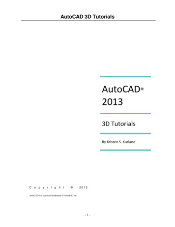
AutoCAD 3D Tutorials1.1 Launch AutoCAD1.ChooseStart, Programs, Autodesk , AutoCAD fromthe Windows program manager.OR2.Double-clickthe AutoCAD icon from your desktop.WorkspacesAutoCAD workspaces are sets of menus, toolbars and dockable windows(such as the Properties palette, DesignCenter, and the Tool paletteswindow) that are grouped and organized so that you can work in acustom, task-oriented drawing environment.1.Clickthe Workspace Switching icon.2.Click3D Basics and OK.-3-
AutoCAD 3D Tutorials1.2 3D Basics InterfaceThe following is AutoCAD’s 3D Basic interface. The 3D Basicribbons are as follows: CreateEditDrawModifySelectionCoordinatesLayers and ViewsThe 3D Basic pulldown menus are as follows: HomeRenderInsertManageOutputPlug-insOnlineExpress Tools-4-
AutoCAD 3D Tutorials1.3 3D Modeling InterfaceThe 3D Modeling panels are as follows: Modeling Mesh Solid Editing Draw Modify Section Coordinates View Selection Layers and GroupsThe 3D Modeling pulldown menus are as follows: Home Solid Surfaces Mesh Render Parametric Insert, Annotate, View, Manage, Output, Plug-ins,Online, and Express Tools-5-
AutoCAD 3D Tutorials1.4 Viewports1.Opena drawing or create simple objects as shown below.2.Clickthe dropdown menu in the shortcut tools and chooseShow Menu Bar.3.ChooseView, Viewports, 4 Viewports.OR4.Type-VPORTS at the command prompt.Command: -VPORTSEnter an option[Save/Restore/Delete/Join/SIngle/?/2/3/4] 4: enterEnter a configuration option [Horizontal/Vertical/Above/Below/Left/Right] Right : enterYour screen will look something like the figure below with four views in oneAutoCAD drawing.-6-
AutoCAD 3D Tutorials1.5 Preset 3D Viewports1.ChooseView, Viewports, New Viewports2.Clickthe dropdown option for Setup and click 3D.3.ChooseFour: Right as the viewport option.-7-
AutoCAD 3D Tutorials1.6 Named Views1.ChooseView, Named Views 2.Clickthe plus ( ) sign beside Preset Views.3.ClickNE Isometric, Set Current, Apply,and OK.Tip:You can also choose View, 3D Views, and any of the preset 3D views.-8-
AutoCAD 3D Tutorials1.7 Steering WheelSteeringWheels are menus that track the cursor over the drawing window,and provide access to 2D and 3D navigation tools from a single interface.SteeringWheels, or “wheels,” are divided into wedges; each wedge containsa single navigation tool. You can start a navigation tool by clicking a wedgeor by clicking and dragging the cursor over a wedge.Full Navigation Wheel1.Clickthe Full Navigation Wheel icon.-9-
AutoCAD 3D Tutorials2D Navigation Wheel (Zoom/Pan)View Object Wheel – Center a model and define the pivot point to use with theOrbit tool. Zoom and orbit a model.Center- 10 -
AutoCAD 3D TutorialsOrbitLook- 11 -
AutoCAD 3D TutorialsWalk/Up/ DownRewindShortcuts1.Right-clickon the wheel to view shortcuts.- 12 -
AutoCAD 3D TutorialsSteering Wheel Settings1.Right-click on the steering wheel and chooseSteeringWheel Settings - 13 -
AutoCAD 3D Tutorials1.8 VPOINT Command (Tripod)Displays a compass and tripod for defining a view rotation. The compassrepresents a two dimensional globe.1.ChooseView, 3D Views, Viewpointor2.TypeVPOINT at the command prompt.Command: VPOINTRotate/ Viewpoint -0.614,-0.614,0.500 :PRESS ENTER3. Clicka point on the compass to define the viewingangle.Point in the center of thecompass is the “ north pole”,looking straight down at thedrawingMiddle ring of thecompass is the“equator”, lookingstraight on at thedrawing.Entire outer ring is the“south pole”, lookingstraight up at thedrawing.Tripod- 14 -
AutoCAD 3D Tutorials1.9 VPOINT Command (Rotate)Enters a rotation angle at the viewpoint prompt.1.TypeVPOINT at the command prompt.Command: VPOINTRotate/ View point -0.614,-0.614,0.500 : R (enter)Enter angle in XY plane from X axis 225 : 225(enter)Enter angle from XY plane 30 : 15 (enter)- 15 -
AutoCAD 3D Tutorials1.10DDVPOINT1.Choose2.Type3.Set4.Picka viewing angle by typing the From X axis and XYPlane angle.ora viewing angle in the 2 graphics Left graphic FromClickX AxisRight graphic In XY PlaneOK.5.View, 3D Views, Viewpoint Preset.orDDVPOINT at the command prompt.Command: DDVPOINT- 16 -
AutoCAD 3D Tutorials1.11 Plan View1.ChooseView, 3D Views, Plan View , World UCS.or2.TypePLAN at the command prompt.Command: PLANEnter an option Current : World- 17 -[CurrentUcs/Ucs/World]
AutoCAD 3D TutorialsAutoCAD 3D – Chapter 2Thickness and Elevation- 18 -
AutoCAD 3D Tutorials2.1 Thickness Command1.Begina new drawing using a 3D Modeling workspace.2.ChooseView, Viewports, 2 Viewports.3.PressENTER for the default of two vertical viewports.4.TypePLAN and World in the left viewport.5.ChooseSE Isometric for the right viewport.6.TypeTHICKNESS at the command prompt.Command: THICKNESSEnter new value for THICKNESS 0.0000 : 37.Drawa 5”,2” rectangle using in the LINE command in theleft view.The lines will have a 3D “thickness” that can be seen in the 3D view.- 19 -
AutoCAD 3D Tutorials2.2 Change Existing Thickness1.Selectthe object whose thickness you would like to change(e.g. one line of the rectangle you drew in 2.1.2.ChooseModify, Properties or right click and chooseProperties 3.Typea new line thickness.The result is a new line thickness for the selected object.- 20 -
AutoCAD 3D Tutorials2.3 ElevationStores the elevation for new objects relative to the current UCS for the currentspace.1.TypeELEVATION at the command prompt.Command: ELEVATIONEnter new value for ELEVATION 0.0000 : 1.002.Drawtwo circles in the left view at the new elevation.Note that they appear to be “floating” 1 unit above theground.- 21 -
AutoCAD 3D Tutorials2.4 Elevation Shortcut1.TypeELEV at the command prompt.Command: ELEVSpecify new default elevation: 1.0000 : 2Specify new default thickness: 3.000 : .52.Drawa new line in the left view to see the elevation andthickness settings.- 22 -
AutoCAD 3D TutorialsAutoCAD 3D – Chapter 3Visualizing Your Model- 23 -
AutoCAD 3D Tutorials3.1 HIDE CommandRegenerates a three-dimensional model with hidden lines1.Opena drawing with 3D objects and display in a 3D view.2.ChooseView, Hide.or3.TypeHIDE at the command prompt.Command: HIDE- 24 -
AutoCAD 3D Tutorials3.2 Visual StylesA visual style is a collection of settings that control the display of edgesand shading in the viewport.Opena drawing with 3D objects and display in a 3D view.ChooseView, Visual Styles and one of the following styleoptions.- 25 -
AutoCAD 3D TutorialsVisual Styles2D WireframeRealisticShades of Gray3D WireframeShaded3D HiddenShaded with EdgesSketchyXRay- 26 -
AutoCAD 3D Tutorials3.3 Visual Style ManagerThe Visual Styles Manager displays sample images of the visual stylesavailable in the drawing. The selected visual style is indicated by a yellowborder, and its settings are displayed in the panel below the sampleimages.ChooseView, Visual Styles, Visual Styles Manager 2.TypeorVISUALSTYLES at the command prompt.Command: VISUALSTYLES3.Choose1.the desired option from one of those available in thedrawing for 2D Wireframe, 3D Wireframe, 3D Hidden,Realistic, or Conceptual options.- 27 -
AutoCAD 3D Tutorials3.4 Visual Styles Panel- 28 -
AutoCAD 3D Tutorials3.5 Adaptive 3D GridWhen you choose a shaded or 3D wireframe visual style, the grid changes froma dotted grid to a rectangular grid. The new grid provides a better sense of amodel’s orientation in 3D. The rectangular grid supports perspective, can displaymajor and minor grid lines, provides color options, and can automatically controlthe grid density when zooming in or out (adaptive grid.) You can change the gridsettings using the drafting settings dialog box.1.ChooseTools, Drafting Settings, and the Snapand Grid TAB.2.TypeDSETTINGS at the command prompt.Command: DSETTINGSTIP:You can turn the adaptive grid on/off from the status bar.- 29 -
AutoCAD 3D TutorialsAutoCAD 3D – Chapter 4Z Coordinates- 30 -
AutoCAD 3D Tutorials4.1 3D CoordinatesEntering 3D Cartesian coordinates (X,Y,Z) is similar to entering 2Dcoordinates (X,Y). In addition to specifying X and Y values, you specify a Zvalue.1.Opena drawing with 3D objects and display in a 3D view.2.Type3DPoly at the command prompt.Command: 3DPOLYSpecify start point of polyline: 1,1,0Specify endpoint of line or [Undo]: 1,2,1Specify endpoint of line or [Undo]: 2,2,1Specify endpoint of line or [Close/Undo]: 2,1,0Specify endpoint of line or [Close/Undo]: 1,1,0The result will be the following lines that are drawn in 3D:- 31 -
AutoCAD 3D Tutorials4.2 Track in Z DirectionWith AutoTrack (polar tracking and object snap tracking), you can track inthe Z direction as well as in the XY plane. Similarly, when Ortho mode isturned on, you can lock the cursor to the Z direction.1.PressF11 or click OSnap Tracking on the status bar if it isnot already on.2.PressF10 or click Polar Tracking on the status bar if it isnot already on.3.Drawa line in the 3D view in the Z direction using tracking.- 32 -
AutoCAD 3D Tutorials4.3 Move in Z Direction1.Opena drawing with 3D objects in it.2.TypeMOVE at the command prompt.Command: moveSelect objects: pick object in 3D viewSelect objects: press enterSpecify base point or displacement:Specify second point of displacement or use first point as displacement : 0,0,1 or use polartracking to move the object.before moveafter move- 33 -
AutoCAD 3D Tutorials4.4 3D Point FiltersDraws in 3D Z direction by filtering X and Y coordinates.1.Opena drawing with 3D objects in it.endpoint to filterUse the CIRCLE command and place it using 3Dpoint filters (.xy)Command: CIRCLESpecify center point for circle or [3P/2P/Ttr (tan tanradius)]: .XYof pick endpoint to filter(need Z): 1Specify radius of circle or [Diameter] 0.2500 :press enter- 34 -
AutoCAD 3D Tutorials4.5 HelixCreates a 2D or 3D spiral.1.Begina new drawing.2.ChooseDraw, Helix.or3.TypeHELIX at the command prompt.Command: helixNumber of turns 3.0000Twist CCWSpecify center point of base: pick pointSpecify base radius or [Diameter] 1.0000 :enter or drag and pickSpecify top radius or [Diameter] 11.0776 :enter or drag and pickSpecify helix height or [Axis endpoint/Turns/turnHeight/tWist] 1.0000 :enter or drag and pick- 35 -
AutoCAD 3D TutorialsAutoCAD 3D – Chapter 5User Coordinate System- 36 -
AutoCAD 3D Tutorials5.1 UCS IconThe UCS icon represents the orientation of the user coordinate system(UCS) axes and the location of the current UCS origin. It also representsthe current viewing direction relative to the XY plane. AutoCAD displaysthe UCS icon differently for 2D, 3D and Paper Space environments.3D UCS icons1.2.ChooseType2D UCSIconPspace UCSICONView, Display, UCS Icon.orUCSICON at the command prompt.Command: ucsiconEnter an option[ON/OFF/All/Noorigin/ORigin/Properties] ON :ONOFFDisplays the UCS icon.Turns off the display of the UCSICON.AllNooriginOriginAffects the display of the UCSICON in all viewports.Always displays the UCS at the lower left corner.Shows the UCS at the 0,0,0 origin of the current UCS.PropertiesChanges the display properties of the UCS icons(s).- 37 -
AutoCAD 3D TutorialsUCS Icon Properties1.1.ChooseView, Display, UCS Icon, Properties.TypeorUCSICON at the command prompt.Command: ucsiconEnter an option[ON/OFF/All/Noorigin/ORigin/Properties] ON : P- 38 -
AutoCAD 3D Tutorials5.2 UCS OverviewThe user coordinate system provides an alternate movable coordinatesystem for coordinate entry, planes of operation, and viewing. MostAutoCAD geometric editing commands are dependent on the location andorientation of the UCS. There are a variety of ways to set the UserCoordinate System using the UCS command.1.TypeUCS at the command prompt.Command: UCSSpecify origin of UCS med/OBject/Previous/View/World/X/Y/Z/ZAxis] World :Aligns the UCS to the selected face of a solid object.Saves or restores a UCS.Lets you define a new UCS by pointing at an object.Restores the previos UCS.Defines a new coordinate system by one of sixmethods: Origin, Z Axis, 3 Point, Object,Face, View X, Y, ZEstablishes a new UCS whose XY plane isperpendicular to your viewing direction (e.g. parallel toyour screen).Restores the world UCSRotates the ucs around a specified axisUCS ToolbarsFound under the AutoCAD Classic Toolbars- 39 -
AutoCAD 3D Tutorials5.3 New (3 Point) UCSThe 3 Point option is one of the easiest ways to define a new UCS on a given 3Dobject.1.Opena drawing with a simple 3D object (e.g. 3D box)2.TypeUCS at the command prompt.Command: UCSSpecify origin of UCS is] World :NSpecify origin of new UCS or[ZAxis/3point/OBject/ Face/View/X/Y/Z] 0,0,0 : 3Specify new origin point 0,0,0 : pick originSpecify point on positive portion of X-axis 3.53,7.73,0.00 : pick point for X directionSpecify point on positive-Y portion of the UCSXY plane 2.53,8.73,0.00 : pick point for Y directionPositive YNew 0,0,0 originPositive X- 40 -
AutoCAD 3D TutorialsNew UCSTIP:You can also click the dropdown beside WCS and click New UCS.- 41 -
AutoCAD 3D Tutorials5.4 Plan UCSTo work in the plan view of your new UCS, use the PLAN command withthe current UCS option. New entities that you draw will be in relation tothis current UCS.1.TypePLAN at the command prompt.Command: PLANEnter an option [Current ucs/Ucs/World] Current :PRESS ENTER- 42 -
AutoCAD 3D Tutorials5.5 World UCSThe World UCS is the only UCS guaranteed to be the same in allAutoCAD drawings and can be used to set the UCS back to its originalstate. This is the UCS you should use when creating Wblocks andinserting Wblocks.1.TypeUCS at the command prompt.Command: UCSSpecify origin of UCS is] World :W- 43 -
AutoCAD 3D
AutoCAD workspaces are sets of menus, toolbars and dockable windows (such as the Properties palette, DesignCenter, and the Tool palettes window) that are grouped and organized so that you can work in a custom, task-oriented drawing environment. 1. Click the Workspace Switching icon. 2. Click 3D Basics and OK. AutoCAD 3D Tutorials - 4 - 1.2 3D Basics Interface The following is AutoCAD’s 3D .