Transcription
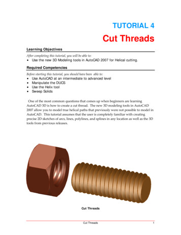
AutoCAD 3D Tutorial3D TutorialsAutoCAD 2007Written by Kristen KurlandCopyright 2007-1-
AutoCAD 3D TutorialAutoCAD 3D – Chapter 13D Interface-2-
AutoCAD 3D Tutorial1.1 Launching AutoCAD 3D1.ChooseStart from the Windows program manager.2.ChoosePrograms, Autodesk ,AutoCAD 2007.WorkspacesAutoCAD workspaces are sets of menus, toolbars and dockable windows(such as the Properties palette, DesignCenter, and the Tool paletteswindow) that are grouped and organized so that you can work in acustom, task-oriented drawing environment.1.Click3D Modeling and OK.-3-
AutoCAD 3D Tutorial1.2 3D InterfaceAutoCAD’s 3D Interface consists of three main areasThe dashboardAnchored palettesA 3D workspace-4-
AutoCAD 3D Tutorial1.3 3D DashboardThe dashboard consists of a set of control panels organized by function.For example, the top control panel contains commands that create andmodify 3D solids; the second control panel contains commands andcontrols used to navigate 3D models.1.Click on one of the panels to expand the display to show a slide-outpanel that has additional controls.Click toexpanddashboardpanel-5-
AutoCAD 3D Tutorial1.4 Viewports1.Choose View, Viewports, 4 Viewports.or2.Type -VPORTS at the command prompt.Command: -VPORTSEnter an option [Save/Restore/Delete/Join/SIngle/?/2/3/4] 4: enterEnter a configuration option [Horizontal/Vertical/Above/Below/Left/Right] Right : enterYour screen will look something like the figure below with four views in oneAutoCAD drawing.-6-
AutoCAD 3D Tutorial1.5 Preset 3D Viewports1.Choose View, Viewports, New Viewports2.Click the dropdown option for Setup and click 3D.3.Choose Four: Right as the viewport option.-7-
AutoCAD 3D Tutorial1.6 Named Views1.Choose View, Named Views 2.Click the plus ( ) sign beside Preset Views.3.Click NE Isometric, Set Current, Apply,and OK.Tip:You can also choose View, 3D Views, and any of the preset 3D views.-8-
AutoCAD 3D Tutorial1.7 VPOINT Command (Tripod)Displays a compass and tripod for defining a view rotation. Thecompass represents a two dimensional globe.1.ChooseView, 3D Views, pointor2.Type VPOINT at the commandprompt.Command: vpoint3. ClickRotate/ Viewpoint -0.614,-0.614,0.500 :(enter)a point on the compass to define the viewing angle.Point in the centerof the compass isthe north poleMiddle ring of thecompassistheequatorEntire outer ringis the south poleTripod-9-
AutoCAD 3D Tutorial1.8 VPOINT Command (Rotate)Enters a rotation angle at the viewpoint prompt.1.Type VPOINT at the command prompt.Command: vpointRotate/ View point -0.614,-0.614,0.500 : R (enter)Enter angle in XY plane from X axis 225 : 225 (enter)Enter angle from XY plane 30 : 15 (enter)- 10 -
AutoCAD 3D Tutorial1.9 DDVPOINT1.Choose View, 3D Views, Viewpoint Preset.or2.Type DDVPOINT at the command prompt.Command: ddvpoint3.Set a viewing angle by typing the From X axis and XY Plane angle.or4.Pick a viewing angle in the 2 graphics Left graphic From X AxisRight graphic In XY Plane5.Click OK.- 11 -
AutoCAD 3D Tutorial1.10 Plan View1.Choose View, 3D Views, Plan View the one of the following:Current UCS, World UCS, Named UCSor2.Type PLAN at the command prompt.Command: planEnter an option [Current Ucs/Ucs/World] Current : World- 12 -
AutoCAD 3D TutorialAutoCAD 3D – Chapter 2Thickness and Elevation- 13 -
AutoCAD 3D Tutorial2.1 Thickness Command1.Begin a new drawing using a 3D Modeling workspace.2.Choose View, Viewports, 2 Viewports.3.Press ENTER for the default of two vertical viewports.4.In the left viewport, type PLAN and World.5.Type THICKNESS at the command prompt.Command: thicknessEnter new value for THICKNESS 0.0000 : 36.In the plan view, draw a rectangle using in the LINE command.The lines will have a 3D “thickness” that can be seen in the 3D view.- 14 -
AutoCAD 3D Tutorial2.2 Change Existing Thickness1.Select the object whose thickness you would like to change (e.g.one line of the rectangle you drew in 2.1.2.Choose Modify, Properties or right click and chooseProperties 3.In the Properties dialog box type a new line thickness.The following result is a new line thickness for the selected object.- 15 -
AutoCAD 3D Tutorial2.3 ElevationStores the elevation for new objects relative to the current UCS for thecurrent space.1.Type ELEVATION at the command prompt.Command: elevationEnter new value for ELEVATION 0.0000 : 1.002.Draw two circles at the new elevation. Note that they appear to be“floating” 1 unit above the ground.- 16 -
AutoCAD 3D Tutorial2.4 Elevation Shortcut1.Type ELEV at the command prompt.Command: elevSpecify new default elevation: 1.0000 : 1Specify new default thickness: 3.000 : 12.Draw a new line to see the elevation and thickness settings.- 17 -
AutoCAD 3D TutorialAutoCAD 3D – Chapter 3Visualizing Your Model- 18 -
AutoCAD 3D Tutorial3.1 HIDE CommandRegenerates a three-dimensional model with hidden lines1.Open a drawing with 3D objects and display in a 3D view.2.Choose View, Hide.or3.Type HIDE at the command prompt.Command: hide- 19 -
AutoCAD 3D Tutorial3.2 Visual StylesA visual style is a collection of settings that control the display of edgesand shading in the viewport.1.Open a drawing with 3D objects and display in a 3D view.2.Choose View, Visual Styles and one of the following style options.2D WireframeRealistic3D WireframeConceptual- 20 -3D Hidden
AutoCAD 3D Tutorial3.3 Visual Style ManagerThe Visual Styles Manager displays sample images of the visual stylesavailable in the drawing. The selected visual style is indicated by a yellowborder, and its settings are displayed in the panel below the sampleimages.1.2.3.Choose View, Visual Styles, Visual Styles Manager orType VISUALSTYLES at the command prompt.Command: visualstylesChoose the desired option from one of those available in thedrawing for 2D Wireframe, 3D Wireframe, 3D Hidden, Realistic, orConceptual options.- 21 -
AutoCAD 3D Tutorial3.4 Adaptive 3D GridWhen you choose a shaded or 3D wireframe visual style, the grid changes froma dotted grid to a rectangular grid. The new grid provides a better sense of amodel’s orientation in 3D. The rectangular grid supports perspective, can displaymajor and minor grid lines, provides color options, and can automatically controlthe grid density when zooming in or out (adaptive grid.) You can change the gridsettings using the drafting settings dialog box.1.Choose View, Visual Styles and one of the following options:3D Wireframe, 3D Hidden, Realistic, or Conceptual.Change the adaptive grid settings1.Choose Tools, Drafting Settings, and the Snap and Grid TAB.- 22 -
AutoCAD 3D TutorialAutoCAD 3D – Chapter 4Z Coordinates- 23 -
AutoCAD 3D Tutorial4.1 3D CoordinatesEntering 3D Cartesian coordinates (X,Y,Z) is similar to entering 2Dcoordinates (X,Y). In addition to specifying X and Y values, you specify a Zvalue.1.Open a drawing with 3D objects and display in a 3D view.2.Type 3DPoly at the command prompt.Command: 3DPOLYSpecify start point of polyline: 1,1,0Specify endpoint of line or [Undo]: 1,2,1Specify endpoint of line or [Undo]: 2,2,1Specify endpoint of line or [Close/Undo]: 2,1,0Specify endpoint of line or [Close/Undo]: 1,1,0The result will be the following lines that are drawn in 3D:- 24 -
AutoCAD 3D Tutorial4.2 Track in Z DirectionWith AutoTrack (polar tracking and object snap tracking), you can track inthe Z direction as well as in the XY plane. Similarly, when Ortho mode isturned on, you can lock the cursor to the Z direction.1.Press F11 or click OSnap Tracking on the status bar if it is notalready on.2.Press F10 or click Polar Tracking on the status bar if it is notalready on.3.In a 3D view, issue the LINE command and draw a line in the Zdirection using tracking.- 25 -
AutoCAD 3D Tutorial4.3 Move in Z Direction1.Open a drawing with 3D objects in it.2.Type MOVE at the command prompt.Command: moveSelect objects: pick object in 3D viewSelect objects: press enterSpecify base point or displacement:Specify second point of displacement or use first point as displacement : 0,0,1 or use polar tracking to movethe object.before moveafter move- 26 -
AutoCAD 3D Tutorial4.4 3D Point FiltersDraws in 3D Z direction by filtering X and Y coordinates.1.Open a drawing with 3D objects in it.endpoint to filter2.Use the CIRCLE command and place it using 3D point filters (.xy)3.Command: circle4.Specify center point for circle or [3P/2P/Ttr (tan tan radius)]: .XY5.of pick endpoint to filter6.(need Z): 17.Specify radius of circle or [Diameter] 0.2500 : press enter- 27 -
AutoCAD 3D TutorialAutoCAD 3D – Chapter 5User Coordinate System- 28 -
AutoCAD 3D Tutorial5.1 UCS IconThe UCS icon represents the orientation of the user coordinate system(UCS) axes and the location of the current UCS origin. It also representsthe current viewing direction relative to the XY plane. AutoCAD displaysthe UCS icon differently for 2D, 3D and Paper Space environments.3D UCS icons1.2.2D UCSIconPspace UCSICONChoose View, Display, UCS Icon.orType UCSICON at the command prompt.Command: ucsiconEnter an option [ON/OFF/All/Noorigin/ORigin/Properties] ON :ONOFFAllNooriginOriginDisplays the UCS icon.Turns off the display of the UCSICON.Affects the display of the UCSICON in all viewports.Always displays the UCS at the lower left corner.Shows the UCS at the 0,0,0 origin of the current UCS.PropertiesChanges the display properties of the UCS icons(s).- 29 -
AutoCAD 3D TutorialUCS Icon Properties1.2.Choose View, Display, UCS Icon, Properties.orType UCSICON at the command prompt.Command: ucsiconEnter an option [ON/OFF/All/Noorigin/ORigin/Properties] ON : P- 30 -
AutoCAD 3D Tutorial5.2 UCS OverviewThe user coordinate system provides an alternate movable coordinatesystem for coordinate entry, planes of operation, and viewing. MostAutoCAD geometric editing commands are dependent on the location andorientation of the UCS. There are a variety of ways to set the UserCoordinate System using the UCS command.1.Type UCS at the command prompt.Command: ucsEnter an option /?/World] World :NewOriginZAxis3 PointObjectFaceViewX/Y/ZDefines a new coordinate system by one of sixmethods: Origin, Z Axis, 3 Point, Object,Face, View X, Y, ZDefines a new UCS by shifting the origin of thecurrent UCS, leaving the direction of the X,Y, and Zaxes unchanged.Allows you to define a new origin.Specifies a UCS by its origin and a point on thepositive X and Y axes.Lets you define a new UCS by pointing at an object.Aligns the UCS to the selected face of a solid object.Establishes a new UCS whose XY plane isperpendicular to your viewing direction (e.g. parallel toyour screen).Rotates the ucs around a specified axisUCS Toolbars- 31 -
AutoCAD 3D Tutorial5.3 3 Point UCSThe 3 Point option is one of the easiest ways to define a new UCS on agiven 3D object.1.Open a drawing with a simple 3D object (e.g. 3D box)2.Type UCS at the command prompt.Command: ucsEnter an option /?/World] World : NSpecify origin of new UCS or [ZAxis/3point/OBject/Face/View/X/Y/Z] 0,0,0 : 3Specify new origin point 0,0,0 : pick originSpecify point on positive portion of X-axis 3.53,7.73,0.00 : pickpoint for X directionSpecify point on positive-Y portion of the UCS XY plane 2.53,8.73,0.00 : pick point for Y directionPositive YNew 0,0,0 origin- 32 Positive X
AutoCAD 3D TutorialNew UCS- 33 -
AutoCAD 3D Tutorial5.4 Plan UCSTo work in the plan view of your new UCS, use the PLAN command withthe current UCS option. New entities that you draw will be in relation tothis current UCS.1.Type PLAN at the command prompt.Command: planEnter an option [Current ucs/Ucs/World] Current : press enter- 34 -
AutoCAD 3D Tutorial5.5 World UCSThe World UCS is the only UCS guaranteed to be the same in allAutoCAD drawings and can be used to set the UCS back to its originalstate. This is the UCS you should use when creating Wblocks andinserting Wblocks.1.Type UCS at the command prompt.Command: ucsCurrent ucs name: *NO NAME*Enter an option /?/World] World W- 35 -
AutoCAD 3D Tutorial5.6 View UCSEstablishes a new coordinate system whose XY plane is perpendicular toyour viewing direction (i.e. parallel to your screen)1.Type UCS at the command prompt.Command: ucsCurrent ucs name: *NO NAME*Enter an option /?/World] World : NSpecify origin of new UCS or [ZAxis/3point/OBject/ Face/View/X/Y/Z] 0,0,0 : e/Save/Del/?/ World :VX.X XXXXXXXXXXXXXXXRegenerates a three-dimensional model with hidden lines1.Open a drawing with 3D objects and display in a 3D view.or2.Choose View, Hide.3.Type HIDE at the command prompt.Command: hide- 36 -
AutoCAD 3D Tutorial5.7 Dynamic UCSYou can use the dynamic UCS to create objects on a planar face of a 3Dsolid without manually changing the UCS orientation.During a command, the dynamic UCS temporarily aligns the XY plane ofthe UCS with a planar face of a 3D solid when you move the cursor overthe face.When the dynamic UCS is active, specified points, and drawing tools,such as polar tracking and the grid, are all relative to the temporary UCSestablished by the dynamic UCS. 1.1.Click the DUCS iconon the status bar or press CTRL D.2.Type any draw command.Command: circle3.Move the cursor to the face of the 3D object that you would like todraw on.4.Click to begin drawing your new object.- 37 -
AutoCAD 3D Tutorial5.8 Naming and Saving a UCSUser coordinate systems can sometimes be complicated and it is oftenuseful to name and save them so you can quickly recall them.1.Type UCS at the command prompt.Command: UCSSpecify origin of UCS is] World : NAEnter an option [Restore/Save/Delete/?]: SEnter name to save current UCS or [?]: LeftSide- 38 -
AutoCAD 3D Tutorial5.9
15.04.2007 · AutoCAD 3D Tutorial - 3 - 1.1 Launching AutoCAD 3D 1. Choose Start from the Windows program manager. 2. Choose Programs, Autodesk ,AutoCAD 2007. Workspaces AutoCAD workspaces are sets of menus, toolbars and dockable windows (such as the Properties palette, DesignCenter, and the Tool palettes window) that are grouped and organized so that you can work in a custom, task