Transcription
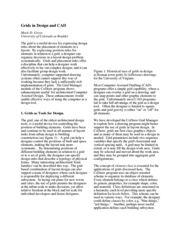
Grids in Design and CADMark D. GrossUniversity of Colorado at BoulderThe grid is a useful device for expressing designrules about the placement of elements in alayout. By expressing position rules forelements in relation to a grid, a designer canorganize decisions in a layout design problemsystematically. Grids and placement rules offera discipline that can help a designer workeffectively to lay out complex designs, and it canalso facilitate group design work.Unfortunately, computer supported drawingsystems often cannot support this way ofworking because they lack a sufficiently richimplementation of grids. The Grid Managermodule of the CoDraw program showsenhancements useful for architectural ComputerAssisted Design. These enhancements wouldenable effective ways of using the computer as adesign tool.1. Grids as Tools for Design.The grid, one of the oldest architectural designtools, is a useful device for controlling theposition of building elements. Grids have beenand continue to be used in all manner of layouttasks from urban design to buildingconstruction (see figure 1) . A grid can help adesigner control the positions of built and spaceelements, making the layout task moresystematic. By determining positions ofdifferent building elements in relation to a gridor to a set of grids, the designer can specifydesign rules that describe a typology of physicalforms. Many interesting architectural 'formfamilies' can be described this way. The gridbased coordination of layout design can alsosupport a team of designers where each designeris responsible for deploying a differentsubsystem. In laying out plans for new townsand cities, the use of grids permits the designersat the urban scale to make decisions, yet allowrelative freedom at the block and lot scale forindividual developers and house designers.Figure 1. Historical uses of grids in designa) Roman town grids; b) Jefferson's drawingsfor the University of VirginiaMost Computer-Assisted Drafting (CAD)programs offer a simple grid capability, where adesigner can overlay a grid on a drawing, andcan snap points and other graphic elements tothe grid. Unfortunately most CAD programsfail to take full advantage of the grid as a designtool. Often the designer is limited to squaregrids and grid gravity is either "on" or "off" forall elements.We have developed the CoDraw Grid Managerto explore how a drawing program might bettersupport the use of grids in layout design. InCoDraw, grids are first class graphics objectsand as many of them may be used in a design asneeded. Grid parameters include two sequencevariables that specify the grid's horizontal andvertical spacing units. A grid may be limited inextent, or it may fill the design work area. Gridsmay be selected and moved about the work area,and they may be grouped into aggregate gridconfigurations.The concept of element class is essential for theapplications of grids discussed here. TheCoDraw program uses an object-orientedscheme to organize its database of elements.Every element belongs to a class which definesits generic properties, for example shape, color,and material. Class definitions are structured ina hierarchy, each level providing more specificdefinition for levels below. This scheme can beused in various ways. For example, the designercould define classes by color, e.g. "blue things,""red things." Another, perhaps more useful,application defines each building subsystem
(concrete foundation, structural steel, partitionwalls) as a class, and within each class definesdifferent component types as subclasses. Thenwe can express generic placement rules for eachclass and subclass. For example, structural steelelements may be programmed to limit placementto relate to a certain grid, with different particularrelations for I-beams, angle-iron, and C-sectionsteel. Using this organization of elementclasses, CoDraw can be programmed to enforcedesign rules expressed in terms of gridrelations.2.1 Layout rules govern placement on agrid.We begin with examples of how grids can beused to express layout rules for architecturaldesign. Then we introduce the CoDraw GridManager, and describes how this programsupports the use of grids to express layoutrules. Finally we discuss this approach toprogramming layout rules in a CAD program,comparing it with other representations for rulesabout shape and form in architectural design.Unlike shape grammars, for example, thisapproach is not generative. The drawingenvironment can be programmed with layoutrules; within these rules the designer worksfreely. The rules are programmed interactively;should they prove too limiting the designer canchange them.Figure 2. Different element-grid relationsTo use a grid as a design tool, the architect mustdetermine rules for placing elements relative tothe grid. The simplest and most obviousplacement rule is that elements center on gridcrossings. However, other rules can beformulated: elements center only on one of theirdimensions; elements center in grid squares; ortheir edges align with grid lines. For example,figure 2 shows different position relations forelements on a simple square grid.2. Grids in Layout Design.To understand the CAD support we want, let'slook at how grids can be used as a layout tool.Three main concepts will emerge: (1) a varietyof kinds of grids are used, from the simplesquare grid, to rectangular and tartan grids. (2)grids can be grouped and used together, and (3)rules about element placement can be expressedin relation to a grid or grids.Figure 3. Various relations between an elementclass and a grid.Figure 3 shows what happens when differentgrid positions are assigned to different types orclasses of elements. In this example, wallcenterlines run along grid lines; concretecolumns are offset on grid crossings, and spaceboundaries (shown in gray) fall along grid lines.In layout design a grid is most often used as anunderlay to a drawing, to organize the positionsof elements. The grid-size is chosen carefully.It is usually related to the dimensions of thespaces to be laid out or the components to beplaced. For example, in laying out woodframing members in a stick-built dwelling, a 16"or 24" grid is useful because in that system 16"or 24" is the on-center spacing between studsand joists, and other components in theconstruction system are compatibly sized.2.2 Subdivided and superimposed grids.2
2.4 Interface conditions where grids meet.Figure 4. Grids can be subdivided andsuperimposed.Figure 6. Grids in different parts of thebuilding meet.Often it is useful to work with one grid at a largescale, and a subdivision of that grid at a smallerscale. The two grids are superimposed andregistered (figure 4). For example, in the 2x4stick building system, in addition to the 16" grid,a larger 48" (4') grid is useful for positioninglarger elements such as gypsum board andplywood panels. A smaller 4" grid can also beused to place light switches, electric outlets, andother hardware.Complex designs often involve different grids indifferent parts of a building (figure 6).When two or more grids are used, the designermust consider the interface condition where theymeet. In some cases special interface elementsand rules are used. For example, a special,round column might be employed to make andmark the transition between two grids atdifferent orientations (figure 7).2.3 Rectangular grids.Figure 7. Special elements and rules may applyat interface conditions.Figure 5. A rectangular grid is a basis for postand beam construction.2.5 Several related grids.Grids need not be square. More often than notthe landscape, building system, or thedirectionality of the design itself suggests arectangular grid. A common use of arectangular grid is to position members of adirectional structural system, for example thepost and beam construction in figure 5.It is often useful to work with several relatedgrids when placing different elements in alayout. We can say that each buildingsubsystem defines a class of elements, and wecan use a different grid for each different classof element. For example, (figure 8) we canrestrict placement of concrete columns to thecrossings of one grid, and program partitionwalls to take their places on the lines of another,offset, grid. A similar effect was obtained infigure 2, where each element class was assigneda different grid relation. In this case, the offsetrelation between these superimposed gridsrepresents an important design decision.3
grids and assignment of subsystem elements tocertain grid relations represents this set ofagreements. Once the team agrees to workwithin these rules, interference conflicts will belimited to a finite and predictable set of locationsand conditions.The initial steps of choosing grids and settingrules about the relations of grids and subsystemelements are crucial to the successful applicationof this method. Some testing of the grids andrules can be valuable at the early stages, to checkthat the rules permit certain desiredconfigurations. Although simple in concept, theapplication of grid techniques in large designprojects requires some experience.Figure 8. Element classes center on differentgrids.2.6 A grid establishes relations betweenelements.Figure 9. Different grids are used for structuraland partition systems.Figure 10. The grid is a device for controllingthe joining conditions of elements.In another example, the major structuralcolumns, beams, and bearing walls are placed ona large, master grid; interior partitions on asecond grid that subdivides the master (figure9), and curtain-wall or skin elements on a third,related, grid. Although the different systems aremanipulated separately in the design process,perhaps by different designers, the coordinationof the grids allows decisions to be maderelatively independently.By programming different element classes totake different positions relative to a grid, thedesigner indirectly controls the relationships ofelements with respect to one other. Rather thanspecifying assembly rules that describe howelements are to join, elements are related to acommon grid. In figure 10, square columns arecentered on grid crossings and walls arecentered only along their lengths, giving eachelement class a direct relationship to the grid,which indirectly defines the position relationsbetween columns and walls.In large projects, the layout design of differentbuilding subsystems and services (structuralsteel, partitions, water, electricity, HVAC) maybe assigned to different experts from differentfirms or different work groups. It is importantthat each expert be able to proceed withoutconstantly checking with other members of theteam. By setting up an initial set of agreementsor rules that govern the placement of elements ofeach subsystem, the designers can proceedrelatively independently. The initial selection of2.7 Tartan or band grids.4
hvacKitchenplumbingFigure 11. A tartan grid can be combined with agrid marking band centerlines.WCGrids need not be always unitary; an alternatingsequence of dimensional units can be used, ftoform a tartan or band grid (figure 11a,b). Atartan grid can be superimposed on a simplergrid that marks the band centerlines (figure11c). A rule can be expressed that requires orprohibits the placement of an element class in aband of the tartan grid, for example "partitionwalls must be located only in the 10 cm bandsof a 10-20cm tartan grid."hvacFigure 13. Each band can house a differentservice.Similarly, building services such as electricity,plumbing, and ventilation can be routed inrestricted zones. This is shown in figure 13.The tartan grid is an important part of a specificdesign methodology for dwelling design(Habraken et al. 1976) (Kroll 1987) and it isalso the basis of description in the Dutchbuilding code standards.2.8 Exceptions and field deployment.Figure 12. Tartan grids allow for variation insize of built elements.Elements can be restricted to center on thecenterline grid, and limited in dimension to staywithin the tartan bands (figure 12). Specifically,their edge coordinates would be constrained tolie within the same band, or range of values. Byexpressing a rule about element dimension, theactual selection of components can be delayedand alternatives evaluated, so long as thecomponents eventually chosen fit within thetartan band.Figure 14. The white columns are exceptions tothe class position relation.When the designer establishes a positionrelation between a grid and an element class, it isunderstood to mean that this is the way elementsof this class are to be placed. That is, everyoccurrence of the element on the grid must takethe specified position relation. However, thedesigner can override the grid relationshipdefined in the class to make a particular elementan exception. For example, the two whitecolumns in figure 14 are exceptions to the class5
relation, which allows columns only on gridcrossings.Figure 16 shows the different dimensions that atartan grid provides. Comparing thesedimensions with the use dimensions requiredfor the functional program can give the designera good idea of how well the grid will work. Forexample, A is 5’, and B is 2’, then the grid willsuggest room widths of 5’, 7’, 9’, 12’, 14’, ., afairly good match for a housing design project.Of course, the actual space available betweenwalls will be diminished by thickness of thewalls. An experienced designer or design firmmay well have a standard grid or set of grids forbasic layout design.Figure 15. a) columns on grid except insiderectangle; b) columns on grid only insiderectangleNormally, a grid-element relation means that ifan element is placed on the grid, it must take itsproper position. Another way to treat anelement-grid placement relation is that for everyoccurrence of the grid condition, an instance ofthe element should be found. Thus, the rule"columns at grid crossings" would produce afield of columns, limited only by the extent ofthe grid. This treatment can b
can snap points and other graphic elements to the grid. Unfortunately most CAD programs fail to take full advantage of the grid as a design tool. Often the designer is limited to square grids and grid gravity is either "on" or "off" for all elements. We have developed the CoDraw Grid Manager to explore how a drawing program might better support the use of grids in layout design. In CoDraw .