Transcription
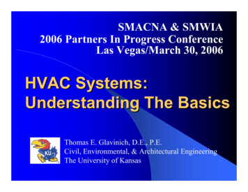
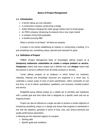
INTRODUCTION:HVAC BASICSAir Handling SystemComponents/Layout:A: DampersB: FiltersHC: Cooling CoilD: Heating CoilE: HumidifierBACD EFF: Supply FanG: DiffusersH: Return FanGAir Flow:Air enters the system from the outside through an air duct and is mixed just before the filters with return airfrom the space. The mixed air is pulled through a set of filters (B) where impurities like particulates and gaseouspollutants are removed. As the air moves forward, it passes over a set of cooling coils (C), where the air is cooled,and depending on the dew point of the passing air, may be dehumidified. The air then passes over a set of heatingcoils (D) where it is heated to the required temperature if necessary. Following the heating coil the air will passover a set of humidification tubes (E). If the relative humidity of the passing air is too low these tubes will addmoisture to the air as it passes. After the humidifier, the air is pulled into the supply fan (F), which then pushes itthrough the supply ductwork, through the diffusers (G) and into the space. The return fan (H) pulls air from thespace and pulls it through the return ductwork. Finally, the air is either exhausted to the outside or returned to theunit to be mixed with new outside air and start the cycle all over again.Refrigerant/Heating Supply:The cooling coils are fed from a source of cooling, such as chillers, a cooling tower, or DX unit. The refrigerantenters the cooling coils, absorbs heat from the air passing the coils, and returns to its source to desorb the heatthat it took in. The heating coils are fed from a heat source such as a boiler or electricity. The heat from these coilsis transferred to the air passing over it.9IPI’s Methodology for Implementing Sustainable Energy-Saving Strategies in Collections Environments (2017)
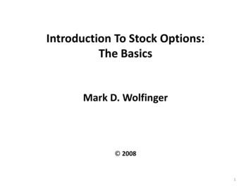
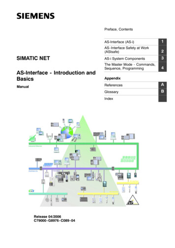
System Variations:1. A system may have multiple sets of filters to remove different levels of impurities.2. The arrangement of the cooling coil and heating coil may vary from unit to unit.3. A cooling coil may not be present in every unit or may be before the outside air dampers for precooling.4. A heating coil may not be present in every unit.5. The main heating coil may be farther down the line in the ductwork in what is called a reheat. As a reheatthe coil will heat air for a specific space just before it is discharged from the ducts.6. A system may utilize a bypass setup where the air can be diverted past the coil(s) if it does not need to betreated.7. Humidification tubes may not be present in every unit or may be farther down in the ductwork just beforethe diffusers.8. A return fan may not be present on every unit if the supply fan creates enough of a draw to pull the airback through the space.Heating/Cooling SystemComponents/Layout:A: DampersGB: FiltersC: Heating CoilD: Cooling CoilE: HumidifierBACD EFFF: Supply FanG: Return FanAir Flow:This type of unit is most common in environments where moisture removal from the air is not much of aconcern. Starting at the outside air intake, air enters the outside air duct and is mixed with return air from thespace just before the filters (B). This mixed air is pulled through a set of filters where impurities are removed. Theair then passes over a set of heating coils (C) where it is heated to the required temperature if necessary. Next theair passes over a set of cooling coils (D); here it is sensibly cooled to the desired temperature if necessary. Afterthe cooling coil the air passes over a set of humidification tubes. If the relative humidity of the air is too low thesetubes will add moisture to the air as it passes. After the humidifiers, the air is pulled into the supply fan (F), whichpushes it through the supply ductwork, through the diffusers and into the space. The return fan (G) will pull in airfrom the space and push it through the return ductwork. The air is either exhausted or returned to the unit to bemixed with outside air and start the cycle all over again.Refrigerant/Heating Supply:The cooling coils are fed from a source of cooling, such as chillers, a cooling tower, or DX unit. The refrigerantenters the cooling coils, absorbs heat from the air passing the coils, and returns to the source to desorb the heat10IPI’s Methodology for Implementing Sustainable Energy-Saving Strategies in Collections Environments (2017)
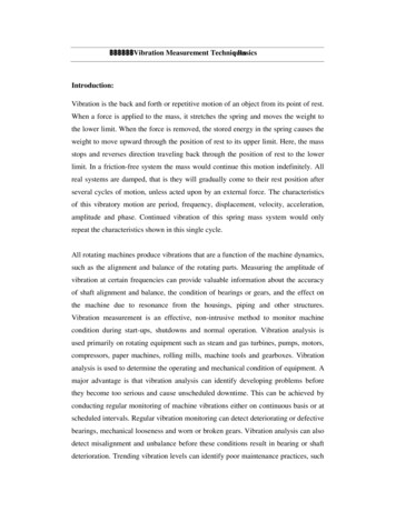
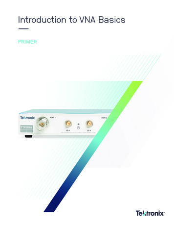
that it took in.The heating coils are fed from a heat source such as a boiler or electricity. The heat from these coils is transferredto the air passing over it.System Variations:1. A system may have multiple sets of filters to remove different levels of impurities.2. A cooling coil may be before the outside air dampers for pre-cooling.3. The system may utilize a bypass setup where the air can be diverted past the coil(s) if it does not need tobe treated.4. Humidification tubes may not be present in every unit or may be farther down in the ductwork just beforethe diffusers.5. A return fan may not be present on every unit if the supply fan creates enough of a draw to pull the airback through the system.Preheat SystemComponents/Layout:A: DampersB: FiltersC: Cooling CoilD: Heating CoilE: HumidifierGHB HACD EFFF: Supply FanG: Return FanH: Preheat CoilsAir Flow:This system is a standard air handling unit that utilizes a preheat coil (H). This coil should only operate duringthe winter months, if the outside air is below freezing. The goal of this coil is to preheat the incoming outside ormixed air to prevent the cooling coil (C) from freezing. These units are typically found in colder regions wherethere is greater risk of low winter temperatures. Starting at the outside air intake, air enters the outside air ductand is heated by the pre-heat coil. The air is then mixed with return air from the space just before the filters(B). This mixed air is pulled through a set of filters where impurities are removed. As the air moves it passesover a set of cooling coils (C), here the air is cooled and depending on the dew point of the passing air, may bedehumidified. The air then passes over a set of heating coils (D) where it is heated to the required temperature ifnecessary. Following the heating coil the air will pass over a set of humidification tubes (E). If the relative humidityof the passing air is too low these tubes will add moisture to the air as it passes. After humidification, the air ispulled through the supply fan (F), which will push it through the supply ductwork, through the diffusers and intothe space. The return fan (G) then pulls in air from the space and pushes it through the return ductwork. The airis either exhausted or returned to the unit to be mixed with outside air and start the cycle all over again.11IPI’s Methodology for Implementing Sustainable Energy-Saving Strategies in Collections Environments (2017)
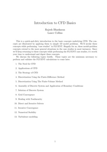
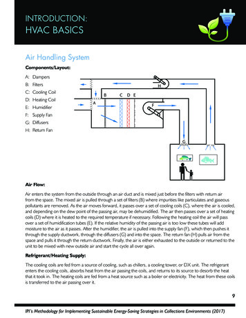
Refrigerant/Coolant Cycle:The cooling coils are fed from a source of cooling, such as chillers, a cooling tower, or DX unit. The refrigerantenters the cooling coils, absorbs heat from the passing air, and returns to its source to desorb the heat that it tookin.The heating coils are fed from a heat source such as a boiler or electricity. The heat from these coils is transferredto the air passing over it.System Variations:1. A system may have multiple sets of filters to remove different levels of impurities.2. The preheat location may be directly at the outside air intake or after the mixed air chamber.3. The main heating coil may be farther down the line in the ductwork in what is called a reheat. As a reheatthe coil will heat air for a specific space just before it is discharged from the ducts.4. A system may utilize a bypass setup where the air can be diverted past the coil(s) if it does not need to betreated.5. Humidification tubes may not be present in every unit or may be farther down in the ductwork just beforethe diffusers.6. A return fan may not be present on every unit if the supply fan creates enough of a draw to pull the airback through the space.Dual Duct Air Handling UnitComponents/Layout:A: FiltersB: Supply FanC: Cooling CoilD: Heating CoilHICABDE: HumidifierEF: Mixing BoxG: DiffuserFH: Outside AirI: Return FanG12IPI’s Methodology for Implementing Sustainable Energy-Saving Strategies in Collections Environments (2017)
Air Flow:Starting at point A on the diagram above, return air passes through the filters on the system and is drawn into thesupply fan. The air is then pushed into the dual duct section of the unit. It will now separate into two ducts, onethat will handle the heating functions and one that will handle the cooling functions:Route One/Cooling – Air enters into the cooling duct (C). Here the air is mixed with outside air. This air nowbecomes a mixed condition of return air and outside air and passes over the cooling coil. Here the air is cooledand, depending on the dew point of the passing air, may be dehumidified. After passing over the cooling coil theair will proceed through the ductwork and be mixed with the heated air in a mixing box (F).Route Two/Heating – Air enters into the heating duct (D). Here the air will pass over a set of heating coils thatheat the passing air. Next it passes over the humidifier. If the relative humidity of the passing air is too low thehumidifier will add moisture to the air and will continue moving through the ductwork towards the mixing box (F).At the Mixing Box – The mixing box is the location in the ductwork where the heating and cooling ductscombine. Here the heated air is mixed with cooled air to achieve the desired temperature for the space. Themixing of air is controlled by a sensor that adjusts dampers on the entering heating or cooling air, opening orclosing them, to ensure that the right mix of air is used to create the desired supply temperature.After the mixing box, the mixed air continues down the ductwork. The air passes through the diffuser (G) andenters the space. Eventually the air is drawn back into the return ductwork and pushed through the return fan (I).From here it will either be exhausted or returned to the start of the system to begin the process again.Refrigerant/Heating Supply:The cooling coils are fed from a source of cooling such as chillers, a cooling tower, or DX unit. The refrigerantenters the cooling coils, absorbs heat from the passing air, and returns to its source to desorb the heat that it tookin.The heating coils are fed from a heat source such as boiler or electricity. The heat from these coils is transferred tothe air passing over it.System Variations:1. An outside air duct can be found either before the cooling coil or before the filters on the air handling unit,depending on the design.2. A system may have multiple sets of filters to remove different levels of impurities.3. If the outside air duct is before the cooling coil the filters may be located before the outside air damper orcooling coil to treat the new air coming into the system.4. A system may utilize a bypass setup where the air can be diverted past the coil(s) if it does not need to betreated.5. Humidification tubes may not be present in every unit. A humidification coil may also be present after thecooling coil.6. A return fan may not be present on every unit if the supply fan creates enough of a draw to pull the airback through the space.13IPI’s Methodology for Implementing Sustainable Energy-Saving Strategies in Collections Environments (2017)
Variable Air Volume (VAV) SystemComponents/Layout:AA: Heating CoilsB: Air Flow SensorC: DampersBCD: ActuatorE: ControllerDF: ContactorsGTFG: ThermostatEAir Flow:VAV stands for variable air volume, and VAV boxes may be a part of an air handling system. They are located inductwork before the air reaches a designated space. Primary air from the air handling unit is pushed downstreamto a VAV box. Just before the VAV box there are a set of dampers (C). These dampers are controlled by an airflow sensor (B) or a space thermostat (G) that will command the actuator (D) to open or close to adjust thevolume of air that is pushed across the heating coils (optional). When air enters a VAV the heating coils insidewill heat the air if necessary. As the air is heated it is pushed out of the VAV box and delivered to the space assecondary air. If no heating is required the contactor will not activate the heating coils and the air passes on withno heating.System Variations:1. A heating coil may not be present in every unit.2. A fan may be located inside the VAV to increase air velocity when air volume is low.3. In some cases a humidifier may be present.Direct Expansion (DX) Individual Air Conditioning SystemComponents/Layout:A: Condenser CoilTB: FansCFC: CompressorD: Expansion ValveOUTSIDEAE: Evaporator CoilF: ThermostatROOMBBEHot Dry AirCool AirDWarm Moist AirWarm Moist Air14IPI’s Methodology for Implementing Sustainable Energy-Saving Strategies in Collections Environments (2017)
Air Flow:Inside the space air is drawn in through the sides of the unit. This air is pushed across the evaporator (cooling)coils where it is cooled to the desired temperature for the room and pushed out the dampers on the front of theunit. The system is designed to sensibly cool the passing air, any dehumidification that may occur is a byproduct ofthis action. As the air is treated it may lose some of its moisture in the process, but the exiting cooler air will havehigher relative humidity than the entering air.On the outside portion of the unit, outside air is drawn in from the sides of the unit. This air is pushed by a fanacross the condenser coils where the passing air will absorb the heat from the coils and be expelled out the rearof the unit. The expelled air will be hotter and drier than the outside air.Refrigerant/Coolant Cycle:Beginning just after the expansion valve (D) the refrigerant starts off as a low temperature, low pressure liquid.Under this low pressure condition the refrigerant has a low boiling point. The refrigerant is pushed through theevaporator coil (E) where it
HVAC BASICS INTRODUCTION: Air Handling System Components/Layout: Dampers Filters Cooling Coil Heating Coil Humidifier Supply Fan Diffusers Return Fan Air Flow: Air enters the system from the outside through an air duct and is mixed just before the filters with return air from the space. The mixed air is pulled through a set of filters (B) where impurities like particulates and gaseous .